EP0488068A2 - Procédé et dispositif pour la fabrication de moules de fonderie - Google Patents
Procédé et dispositif pour la fabrication de moules de fonderie Download PDFInfo
- Publication number
- EP0488068A2 EP0488068A2 EP91119928A EP91119928A EP0488068A2 EP 0488068 A2 EP0488068 A2 EP 0488068A2 EP 91119928 A EP91119928 A EP 91119928A EP 91119928 A EP91119928 A EP 91119928A EP 0488068 A2 EP0488068 A2 EP 0488068A2
- Authority
- EP
- European Patent Office
- Prior art keywords
- molding
- molding material
- sieve
- box
- filling vessel
- Prior art date
- Legal status (The legal status is an assumption and is not a legal conclusion. Google has not performed a legal analysis and makes no representation as to the accuracy of the status listed.)
- Granted
Links
Images



Classifications
-
- B—PERFORMING OPERATIONS; TRANSPORTING
- B22—CASTING; POWDER METALLURGY
- B22C—FOUNDRY MOULDING
- B22C15/00—Moulding machines characterised by the compacting mechanism; Accessories therefor
-
- B—PERFORMING OPERATIONS; TRANSPORTING
- B22—CASTING; POWDER METALLURGY
- B22C—FOUNDRY MOULDING
- B22C5/00—Machines or devices specially designed for dressing or handling the mould material so far as specially adapted for that purpose
- B22C5/12—Machines or devices specially designed for dressing or handling the mould material so far as specially adapted for that purpose for filling flasks
Definitions
- the invention relates to a method for producing casting molds from free-flowing molding material, in particular foundry molding sand, which is contained in a filling vessel and, by means of the same, is moved into a molding station with a receiving table, model plate, molding box, optionally a filling frame, and is transferred there into the molding box, with classified fine-grained The molding material is applied to the model and then further molding material is transferred to the molding box. Furthermore, the invention is directed to an apparatus for performing this method.
- the model When producing casting molds from free-flowing molding materials, which are compacted above the model in a molding box, it is essential that the model is shown with a sharp contour in the molding material. Furthermore, it depends on the density and Hardness of the shape in the area close to the model. Among other things, the molding material must have good flow properties and, if possible, a comparatively small grain size. Since the molding material is reused after the casting of the molding box for reasons of cost and environmental protection and must be prepared for this purpose, compliance with the aforementioned requirements is of particular importance. The molding material to be processed is therefore crushed and converted back into free-flowing form. Nevertheless, it cannot be avoided that the size distribution is not uniform, in particular larger molding material agglomerates remain. Such agglomerates can also form and build up again at any time during the transport of the molding material, so that classification stages (sieves) switched on in the preparation process of the molding material only provide limited relief.
- classification stages switched on in the preparation process of the molding material only provide limited relief.
- the molding material is transported to the molding system by means of conveyors and there - if necessary via an intermediate buffer, e.g. B. a silo - handed over to the filling vessel.
- an intermediate buffer e.g. B. a silo - handed over to the filling vessel.
- the filling vessel and the compression device are arranged to be movable above the receiving table with the molding box and can optionally be moved into the molding station by first bringing the filling vessel over the molding box, delivering the necessary amount of molding material to the molding box and then the compression device via the molding box is driven to compress the molding material in the molding box.
- the filling vessel reaches a filling position.
- model sand is first placed on the model. This was previously done by hand.
- a screening station has already been arranged outside the molding station, into which the molding box with model plate is placed before it reaches the molding station.
- the model sand is sieved onto the model with a vibrating sieve. The sieve residue is discarded. Apart from the insufficient loosening, the throughput is low and the cycle time of the molding system increases considerably. There is also increased construction costs and space requirements.
- the invention has for its object to propose a method by means of which molds with a perfect shape contour and consistent quality can be produced with a high cycle time. Furthermore, the invention is intended to provide a device which allows the same goals to be achieved.
- this object is achieved in that at least a portion of the molding material which is sufficient to cover the surface of the model is screened off in the filling vessel before or during the transfer to the molding box and transferred to the molding box as a sieve pass, and in that the remaining amount is screened off directly into the Molding box is passed.
- At least a subset of the molding material contained in the filling vessel is classified, that is to say it is narrowed to a size corresponding to the mesh size of the sieve.
- This partial quantity arrives first in the molding box and thus first on the model, so that the higher quality requirements there can be met by a comparatively small molding material size and uniform size distribution.
- the entire molding material requirement of a molding box can be screened off, but the time required will generally be too great for this. Therefore, only a partial quantity sufficient to cover the surface of the model is screened off as "model sand" and the remaining quantity is transferred directly to the molding box.
- the invention is based on the known fact that the quality requirements for the molding material are not to be set so high outside the model-related range, so that coarser molding material particles, as well as agglomerates, may also be present there. Since only comparatively small quantities are required to cover the model surfaces, the screening process can easily be integrated into the machine cycles that are common today. The invention also leaves open the possibility of delivering the entire molding material requirement directly to the molding material in the case of molds with not so high quality requirements.
- the molding material can be loosened during sieving, on the one hand to effect a comminution process and on the other hand to accelerate the classification on the sieve surface.
- a particularly favorable method of operation is obtained when the partial amount of the molding material is sieved and collected during the travel movement of the filling vessel between a ready position and the molding station and is transferred to the molding box after reaching the molding station.
- the molding material required to cover the model contour is generated during an already existing dead time (travel movements of the filling vessel) and is available in the desired quantity at the moment when the filling vessel reaches the molding station.
- the invention provides that the filling vessel has a strainer retaining the molding material and a moving device for the molding material, and that the strainer can be moved into a position for transferring the screen residue into the molding box.
- the sieve provided according to the invention for the production of the "model sand” forms at least part of the filling vessel in such a way that it is able to retain the molding material.
- the moving material loosens and loosens the molding material lying on the sieve surface and at the same time promotes the passage of the finer molding material particles through the sieve. If the height of the model or molding box is low, the entire molding material requirement can be screened off if necessary. As a rule, however, you will only sieve a partial quantity and the sieve residue transferred directly into the molding box by moving the sieve accordingly.
- a preferred embodiment of the device according to the invention is characterized in that the screen is designed as a horizontally mounted cylinder screen and has an opening on its jacket.
- the design as a cylinder sieve, which is arranged in the filling vessel, makes it possible, on the one hand, to accommodate a relatively large amount of molding material, in particular the entire need for a molding box in the sieve, and to loosen the molding material by means of a movement device rotating around the bearing axis. Furthermore, the cylinder screen can be emptied into the molding box in a simple manner by pivoting about its axis, so that even if there is no need for finer model sand, the entire molding material requirement can be transferred from the filling vessel to the molding box in the shortest possible time.
- the opening of the cylinder screen has an opening angle in the range of at least 90 °. This also makes it easier to transfer the molding material to the sieve.
- the cylinder sieve is formed by two partial cylinder shells, which can be pivoted in the manner of a fish mouth closure optionally into a closed position in which they form the sieve and an open position in which they are essentially outside the falling path of the molded materials are arranged.
- the molding material directly into the molding box if necessary, ie if the use of sieved sand can be dispensed with, by using the partial cylinder shells be pivoted away on opposite sides, so that the molding material falls directly onto the bottom closure of the filling vessel and is ready for transfer to the molding box. In this case, the movement device remains stopped.
- the sieve residue after the sieving process has been carried out can be pivoted by pivoting the partial cylinder shells, i.e. by opening the fish mouth closure, empty it very quickly into the mold box, which also leads to shorter cycle times.
- the partial cylinder shells extend over an arc angle of approx. 90 °, i.e. each have the shape of a quarter-cylinder shell.
- a movement device which rotates or oscillates about its bearing axis is arranged in the cylinder screen and can, for example, have strips which extend over the screen surface. These in turn are expediently arranged on a turnstile driven in the bearing axis of the cylinder screen.
- the circulation and loosening of the molding material can be promoted in that several short strips one after the other in the axial extension of the cylinder screen are arranged, which are preferably set at an angle to the bearing axis of the cylinder screen.
- a collecting device for receiving the sieved partial amount of the molding material is arranged at a distance below the sieve and that the collecting device is set up for delivering this partial amount to the molding box.
- the collecting device picks up the part of the molding material and is designed in such a way that it can deliver this part to the molding box at the molding station.
- the collecting device can be designed as a kind of shutter. This can be the conventional blind closure of the filling vessel if the cylinder screen is arranged inside the filling vessel.
- the collecting device in the manner of a fish mouth closure, which concentrically engages under the cylinder sieve and seals the filling vessel at the bottom.
- the molding system according to Figure 1 has a compression device 1, z. B. in the form of an air pulse unit, and a filling vessel 2, both of which can be moved, for example by means of a common carriage 3, in the plane of the drawing.
- a filling frame 4 is arranged below the compression device 1.
- a roller conveyor 7 for the molding boxes 8 which move through the molding station from left to right in the drawing.
- the filling vessel 2 is filled on a conveyor belt 9 in the embodiment shown. Instead, a storage silo can also be provided, into which the conveyor belt 9 releases the molding material. Inside the filling vessel 2 a sieve 10 is arranged which retains the molding material transferred into the filling vessel.
- the screen 10 is designed as a cylindrical screen and is provided with an opening 11 on its jacket.
- the opening has an opening angle of at least 90 °.
- the opening 11 is located below a funnel-like indentation 12 of the filling vessel 2.
- a turnstile Arranged inside the cylinder screen 10 on a drive shaft 13 is a turnstile, not shown, which is provided with strips 14, preferably in the form of brush strips, which stroke over the inside of the cylinder screen and circulate the molding material contained in the cylinder screen 10.
- the movement of the strips 14 classifies the fine molding material particles through the cylinder sieve and, as a sieve passage, reaches a collecting device 16 which, in the exemplary embodiment according to FIGS. 2 and 4, is designed as a blind closure of the filling vessel 2.
- the cylinder screen 10 is then rotated through 180 °, so that the unclassified molding material 15 still contained in the cylinder screen reaches the molding box (FIG. 4).
- the exemplary embodiment according to FIGS. 5 to 7 differs from that according to FIGS. 2 and 4 only by the different design of the collecting device 16.
- it is designed as a fish mouth closure with two jaws 18, which are arranged concentrically to the drive shaft 13 and from which in FIG 5, holding the sieve passage 17 in the open position shown in FIG. 6, in which the model sand gets into the molding box.
- the cylinder sieve 10 is then rotated into the position according to FIG. 7 and the sieve residue is dispensed to fill the molding box.
- the collecting device 16 also forms the lower closure of the filling vessel 2.
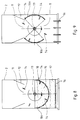
- the exemplary embodiment according to FIGS. 8 and 9 shows a modification of the cylinder screen of the embodiment according to FIGS. 2 to 4.
- the cylinder screen 10 consists of two partial cylinder shells 10a, which in their closed position shown in FIG. 8 form a half cylinder.
- the partial cylinder shells 10a are rotatably mounted concentrically to the drive shaft 13 and can be pivoted into an opening position, shown in FIG. 9, in which they release both an upper and a lower opening 11 and are arranged essentially outside the path of the molding material.
- the open position shown in FIG. 9 can be assumed on the one hand in order to allow the molding material which has been introduced into the filling vessel 2 from above to reach the collecting device 16 and thus the model without sieving.
- the cylinder screen can be opened after the screening process according to FIG. 8 by swiveling up the partial cylinder shells 10a.
- a cylinder screen 10 in the form of partial cylinder shells 10a can also be used in the exemplary embodiment shown in FIGS. 5 to 7, as shown in FIGS. 10 and 11.
- both the cylinder sieve 10 and the collecting device 16 are designed as a fish mouth closure with swiveling jaws 10 and 18, the jaws being arranged concentrically and being driven by a common drive device.
Landscapes
- Engineering & Computer Science (AREA)
- Mechanical Engineering (AREA)
- Casting Devices For Molds (AREA)
- Molds, Cores, And Manufacturing Methods Thereof (AREA)
- Combined Means For Separation Of Solids (AREA)
Applications Claiming Priority (2)
| Application Number | Priority Date | Filing Date | Title |
|---|---|---|---|
| DE4038173A DE4038173A1 (de) | 1990-11-30 | 1990-11-30 | Verfahren und vorrichtung zum herstellen von giessformen |
| DE4038173 | 1990-11-30 |
Publications (3)
| Publication Number | Publication Date |
|---|---|
| EP0488068A2 true EP0488068A2 (fr) | 1992-06-03 |
| EP0488068A3 EP0488068A3 (en) | 1993-09-01 |
| EP0488068B1 EP0488068B1 (fr) | 1997-02-12 |
Family
ID=6419267
Family Applications (1)
| Application Number | Title | Priority Date | Filing Date |
|---|---|---|---|
| EP91119928A Expired - Lifetime EP0488068B1 (fr) | 1990-11-30 | 1991-11-22 | Procédé et dispositif pour la fabrication de moules de fonderie |
Country Status (4)
| Country | Link |
|---|---|
| EP (1) | EP0488068B1 (fr) |
| JP (1) | JP3255951B2 (fr) |
| DE (2) | DE4038173A1 (fr) |
| ES (1) | ES2098302T3 (fr) |
Families Citing this family (1)
| Publication number | Priority date | Publication date | Assignee | Title |
|---|---|---|---|---|
| CN105690590B (zh) * | 2016-04-01 | 2017-09-26 | 西安医学院 | 一种口腔临床用合成橡胶印模材料的制备方法 |
Family Cites Families (2)
| Publication number | Priority date | Publication date | Assignee | Title |
|---|---|---|---|---|
| CH462392A (de) * | 1967-08-16 | 1968-09-15 | Buehrer Erwin | Verfahren zum Dosieren von zwei Formsandsorten in einen Formkasten einer Giessereiform |
| CH665787A5 (de) * | 1984-07-11 | 1988-06-15 | Fischer Ag Georg | Verfahren und vorrichtung zum verdichten von koernigen formstoffen. |
-
1990
- 1990-11-30 DE DE4038173A patent/DE4038173A1/de not_active Withdrawn
-
1991
- 1991-11-22 DE DE59108542T patent/DE59108542D1/de not_active Expired - Fee Related
- 1991-11-22 EP EP91119928A patent/EP0488068B1/fr not_active Expired - Lifetime
- 1991-11-22 ES ES91119928T patent/ES2098302T3/es not_active Expired - Lifetime
- 1991-11-28 JP JP31426991A patent/JP3255951B2/ja not_active Expired - Fee Related
Also Published As
| Publication number | Publication date |
|---|---|
| EP0488068B1 (fr) | 1997-02-12 |
| EP0488068A3 (en) | 1993-09-01 |
| ES2098302T3 (es) | 1997-05-01 |
| JP3255951B2 (ja) | 2002-02-12 |
| DE4038173A1 (de) | 1992-06-04 |
| DE59108542D1 (de) | 1997-03-27 |
| JPH05177301A (ja) | 1993-07-20 |
Similar Documents
| Publication | Publication Date | Title |
|---|---|---|
| DE102013223407A1 (de) | Vorrichtung und Verfahren zum schichtweisen Herstellen eines dreidimensionalen Objekts sowie zum Auspacken des fertiggestellten Objekts | |
| DE2550879C3 (de) | Vorrichtung zur bekannten Wiederverwertung des Abfalls von wärmegehärtetem Kunststoff | |
| DE102015115486A1 (de) | Fraktionelles Selektieren eines Altsandstroms nach einer Gussherstellung | |
| DE2435943A1 (de) | Verfahren und vorrichtung zum behandeln von giessereisand | |
| DE2202311A1 (de) | Verfahren und System zum Schleifstrahlen | |
| DE3900664A1 (de) | Verfahren und vorrichtung zum reinigen des rohmaterial-beschickungsbehaelters einer verarbeitungsmaschine | |
| DE2606926A1 (de) | Verfahren zum herstellen von als pellets vorbehandelten chargen bei der herstellung von glas | |
| EP2192999A1 (fr) | Sélection d'un sable de décochage résultant de la production de pièces coulées et dispositif correspondant | |
| DE3228735A1 (de) | Fahrbare oder verfahrbare zerkleinerungsanlage | |
| DE202019004297U1 (de) | Überlaufeinrichtung für eine Vorrichtung zur schichtweisen Herstellung dreidimensionaler Objekte aus Partikelmaterial | |
| EP0488068B1 (fr) | Procédé et dispositif pour la fabrication de moules de fonderie | |
| DE2319146A1 (de) | Vorrichtung zum bearbeiten von werkstuecken | |
| DE102021207668A1 (de) | Staubverfestigungsvorrichtung | |
| DE2623882A1 (de) | Geraet zur wiedergewinnung und regenerierung von fuer giessereien bestimmtem formsand | |
| DE102017220640A1 (de) | Vorrichtung zum Auspacken zumindest eines Bauteils sowie ein Verfahren, um dieses Auspacken zu realisieren | |
| DE3341981A1 (de) | Verfahren und vorrichtung zum herstellen von kernen aus gruensand | |
| EP0519324B1 (fr) | Dispositif pour broyer du sable | |
| DE102007024480A1 (de) | Zuführvorrichtung für Glasrohmaterial und Zuführverfahren für Glasrohmaterial | |
| DE2225939A1 (de) | Verfahren und vorrichtung zur herstellung von formlingen | |
| DE2710128C3 (de) | Verfahren zum Granulieren eines Pulvers | |
| DE3822787C2 (fr) | ||
| DE2428833C3 (de) | Gießerei-Altsand-Aufbereitung | |
| DE1097905B (de) | Einrichtung zum Entnehmen von Schuettgut aus einem Silo, Schacht, Behaelter od. dgl. | |
| DE4001268A1 (de) | Siebtrommel zum behandeln von kompost, biomasse oder dergleichen aufgabegut sowie vorrichtung dafuer | |
| CH690322A5 (de) | Verfahren und Vorrichtung zur Regenerierung von Giesserei-Altsand. |
Legal Events
| Date | Code | Title | Description |
|---|---|---|---|
| PUAI | Public reference made under article 153(3) epc to a published international application that has entered the european phase |
Free format text: ORIGINAL CODE: 0009012 |
|
| AK | Designated contracting states |
Kind code of ref document: A2 Designated state(s): CH DE ES FR GB IT LI |
|
| PUAL | Search report despatched |
Free format text: ORIGINAL CODE: 0009013 |
|
| AK | Designated contracting states |
Kind code of ref document: A3 Designated state(s): CH DE ES FR GB IT LI |
|
| 17P | Request for examination filed |
Effective date: 19940129 |
|
| 17Q | First examination report despatched |
Effective date: 19950918 |
|
| GRAG | Despatch of communication of intention to grant |
Free format text: ORIGINAL CODE: EPIDOS AGRA |
|
| GRAH | Despatch of communication of intention to grant a patent |
Free format text: ORIGINAL CODE: EPIDOS IGRA |
|
| GRAH | Despatch of communication of intention to grant a patent |
Free format text: ORIGINAL CODE: EPIDOS IGRA |
|
| GRAA | (expected) grant |
Free format text: ORIGINAL CODE: 0009210 |
|
| AK | Designated contracting states |
Kind code of ref document: B1 Designated state(s): CH DE ES FR GB IT LI |
|
| REG | Reference to a national code |
Ref country code: CH Ref legal event code: EP |
|
| REG | Reference to a national code |
Ref country code: CH Ref legal event code: NV Representative=s name: TROESCH SCHEIDEGGER WERNER AG |
|
| REF | Corresponds to: |
Ref document number: 59108542 Country of ref document: DE Date of ref document: 19970327 |
|
| ITF | It: translation for a ep patent filed | ||
| REG | Reference to a national code |
Ref country code: ES Ref legal event code: FG2A Ref document number: 2098302 Country of ref document: ES Kind code of ref document: T3 |
|
| ET | Fr: translation filed | ||
| GBT | Gb: translation of ep patent filed (gb section 77(6)(a)/1977) |
Effective date: 19970805 |
|
| PLBE | No opposition filed within time limit |
Free format text: ORIGINAL CODE: 0009261 |
|
| STAA | Information on the status of an ep patent application or granted ep patent |
Free format text: STATUS: NO OPPOSITION FILED WITHIN TIME LIMIT |
|
| 26N | No opposition filed | ||
| REG | Reference to a national code |
Ref country code: GB Ref legal event code: IF02 |
|
| PGFP | Annual fee paid to national office [announced via postgrant information from national office to epo] |
Ref country code: GB Payment date: 20021106 Year of fee payment: 12 |
|
| PGFP | Annual fee paid to national office [announced via postgrant information from national office to epo] |
Ref country code: ES Payment date: 20021126 Year of fee payment: 12 Ref country code: DE Payment date: 20021126 Year of fee payment: 12 |
|
| PGFP | Annual fee paid to national office [announced via postgrant information from national office to epo] |
Ref country code: FR Payment date: 20021129 Year of fee payment: 12 |
|
| PGFP | Annual fee paid to national office [announced via postgrant information from national office to epo] |
Ref country code: CH Payment date: 20030128 Year of fee payment: 12 |
|
| PG25 | Lapsed in a contracting state [announced via postgrant information from national office to epo] |
Ref country code: GB Free format text: LAPSE BECAUSE OF NON-PAYMENT OF DUE FEES Effective date: 20031122 |
|
| PG25 | Lapsed in a contracting state [announced via postgrant information from national office to epo] |
Ref country code: ES Free format text: LAPSE BECAUSE OF NON-PAYMENT OF DUE FEES Effective date: 20031124 |
|
| PG25 | Lapsed in a contracting state [announced via postgrant information from national office to epo] |
Ref country code: LI Free format text: LAPSE BECAUSE OF NON-PAYMENT OF DUE FEES Effective date: 20031130 Ref country code: CH Free format text: LAPSE BECAUSE OF NON-PAYMENT OF DUE FEES Effective date: 20031130 |
|
| PG25 | Lapsed in a contracting state [announced via postgrant information from national office to epo] |
Ref country code: DE Free format text: LAPSE BECAUSE OF NON-PAYMENT OF DUE FEES Effective date: 20040602 |
|
| GBPC | Gb: european patent ceased through non-payment of renewal fee |
Effective date: 20031122 |
|
| REG | Reference to a national code |
Ref country code: CH Ref legal event code: PL |
|
| PG25 | Lapsed in a contracting state [announced via postgrant information from national office to epo] |
Ref country code: FR Free format text: LAPSE BECAUSE OF NON-PAYMENT OF DUE FEES Effective date: 20040730 |
|
| REG | Reference to a national code |
Ref country code: FR Ref legal event code: ST |
|
| REG | Reference to a national code |
Ref country code: ES Ref legal event code: FD2A Effective date: 20031124 |
|
| PG25 | Lapsed in a contracting state [announced via postgrant information from national office to epo] |
Ref country code: IT Free format text: LAPSE BECAUSE OF NON-PAYMENT OF DUE FEES Effective date: 20051122 |