EP0488176B1 - Farbbildverarbeitungsgerät - Google Patents
Farbbildverarbeitungsgerät Download PDFInfo
- Publication number
- EP0488176B1 EP0488176B1 EP91120195A EP91120195A EP0488176B1 EP 0488176 B1 EP0488176 B1 EP 0488176B1 EP 91120195 A EP91120195 A EP 91120195A EP 91120195 A EP91120195 A EP 91120195A EP 0488176 B1 EP0488176 B1 EP 0488176B1
- Authority
- EP
- European Patent Office
- Prior art keywords
- color
- color image
- image
- processing apparatus
- data
- Prior art date
- Legal status (The legal status is an assumption and is not a legal conclusion. Google has not performed a legal analysis and makes no representation as to the accuracy of the status listed.)
- Expired - Lifetime
Links
- 239000003086 colorant Substances 0.000 claims description 9
- 238000009835 boiling Methods 0.000 claims description 2
- 238000007599 discharging Methods 0.000 claims description 2
- 238000005070 sampling Methods 0.000 claims description 2
- 238000003672 processing method Methods 0.000 claims 1
- 230000006870 function Effects 0.000 description 18
- 238000010586 diagram Methods 0.000 description 6
- 238000006243 chemical reaction Methods 0.000 description 5
- 238000003705 background correction Methods 0.000 description 2
- 230000000873 masking effect Effects 0.000 description 2
- 238000000034 method Methods 0.000 description 2
- 230000003287 optical effect Effects 0.000 description 2
- 238000000605 extraction Methods 0.000 description 1
- 230000035945 sensitivity Effects 0.000 description 1
- 239000007787 solid Substances 0.000 description 1
Images





Classifications
-
- H—ELECTRICITY
- H04—ELECTRIC COMMUNICATION TECHNIQUE
- H04N—PICTORIAL COMMUNICATION, e.g. TELEVISION
- H04N1/00—Scanning, transmission or reproduction of documents or the like, e.g. facsimile transmission; Details thereof
- H04N1/46—Colour picture communication systems
- H04N1/56—Processing of colour picture signals
- H04N1/60—Colour correction or control
- H04N1/6094—Colour correction or control depending on characteristics of the input medium, e.g. film type, newspaper
-
- H—ELECTRICITY
- H04—ELECTRIC COMMUNICATION TECHNIQUE
- H04N—PICTORIAL COMMUNICATION, e.g. TELEVISION
- H04N1/00—Scanning, transmission or reproduction of documents or the like, e.g. facsimile transmission; Details thereof
- H04N1/46—Colour picture communication systems
- H04N1/56—Processing of colour picture signals
Definitions
- the present invention relates to a color image processing apparatus, which can automatically change processing according to the types of color images.
- a conventional color image processing apparatus designates a set of color correction functions for a color image, as disclosed in, e.g., Japanese Laid-Open Patent Application No. 61-296858.
- the document EP-A-0 415 648 (Art. 54(3) publication) discloses a color image processing apparatus in which image processing is performed on the basis of an edge discrimination using a membership function in order to classify types of color images.
- document EP-A-0 267 805 discloses an image processing apparatus, wherein a LUT used in a logarithmic conversion is manually switched by an operator using an operation panel according to whether input image is a reflected image, a negative image or a positive film.
- Fig. 1 is a block diagram showing an arrangement according to the first embodiment of the present invention.
- a controller A of a color image processing apparatus comprises an image memory 1 for storing image data input from electronic equipment such as a computer, a CPU 2 for controlling respective circuit portions, and determining parameters for a color correction processing circuit on the basis of a program and fuzzy deducing rule stored in a ROM 4, a work RAM 3 for the CPU 2, and a color correction processing circuit 5 for performing color correction processing on the basis of the parameters for the color correction processing circuit from the CPU 2.
- the output from the processing circuit 5 is output to a color image recording device 10.
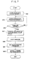
- Various types of color images supplied from a computer are stored in the image memory 1 as R, G, and B signals (S10).
- the CPU 2 samples N sets of R, G, and B signals from the image memory using the RAM 3 and ROM 4 (S13, S15; Fig. 5).
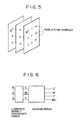
- the sampled N sets of R, G, and B signals can be plotted on the coordinate system defined by a cubic color space shown in Fig. 2 if a maximum value of each of the R, G, and B signals is represented by "1", and a minimum value thereof is represented by "0".
- the cube shown in Fig. 2 is divided into some divisional color spaces, as shown in, e.g., Fig. 3, and these spaces are stored in advance in the ROM 4.
- FIG. 3 shows an R-G signal plane of the cube shown in Fig. 2.
- the cube is three-dimensionally divided.
- the CPU 2 counts the number of signals of the N sets of R, G, and B signals, or the number of colors, which can fall within the divisional color spaces (S17). The count results are stored in the RAM 3.
- a fuzzy deducing operation is performed on the basis of these data (S19).
- histograms of the above-mentioned divisional color spaces are formed so as to deduce the type of an image stored in the memory 1.
- the following fuzzy deducing rules are prepared.
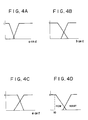
- Figs. 4A to 4D are graphs showing membership functions of the number of pixels or the number of colors in the corresponding regions, and these functions are stored in advance in the ROM 4.
- the rule 1 ⁇ will be exemplified below.
- the number of colors is N.
- the number of colors is relatively small, and is about 10. Therefore, upon application of the rule 1 ⁇ , if a "few" function shown in Fig. 4D representing the membership function of an "image including a small number of colors" is used, an output value is "1".
- the membership functions shown in Figs. 4A, 4B and 4C based on other rules are set such that the output does not become "1" in this case. Therefore, the rule 1 ⁇ indicating that this image is a kind of CG image is established.
- the parameters of the color correction processing circuit 5 those for the CG image are set. For example, the parameters for improving saturation of colors are set.
- corrected image signals are supplied from the image memory to the color image recording device.
- the rules other than the rule 1 ⁇ are also executed, and the CPU 2 is programmed to make a decision when a rule having a largest value as a then-part corresponding to an if-part of the rule is established. If there are rules having the same then-part value, the priority order is determined in advance.
- Fig. 6 shows an arrangement of the color correction processing circuit 5 shown in Fig. 2.
- the circuit 5 includes a luminance density conversion RAM 20, and a hardware circuit 22 for executing masking processing and UCR processing.
- a luminance density conversion table or masking and UCR coefficients may be changed.
- the color correction processing circuit is not limited to an arrangement including two circuit components, as shown in Fig. 6.
- the circuit may comprise a ROM, and ROM addresses may be switched according to the type of image discriminated by the CPU 2.
- the regions shown in Fig. 3 may be further divided, and the number of membership functions shown in Figs. 4A to 4D may be increased to increase the number of types of images to be discriminated.
- an image fetched from a computer is fuzzy-deduced by an arithmetic means so as to discriminate the type of image.
- the parameters for the color correction processing circuit can be set. As a result, a good image can be output without troubling a user.
- the feature of image data stored in a memory is discriminated to determine whether the input image is a CG image or a scanner image.
- a positive or negative image is determined based on image data stored in a memory.
- Fig. 8 is a block diagram showing the second embodiment of the present invention
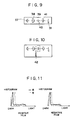
- Fig. 9 is a view showing an arrangement of a film reader.
- the film reader includes a light source 37 for illuminating a film. Light emitted from the light source is radiated on a film 40 attached to a film holder 39 via a condenser lens. The light transmitted through the film is focused on a color solid state image pickup device 31 through a projection lens 41. The image pickup device 31 scans a film image while being moved in a direction of an arrow in Fig. 9. A film image signal read in this manner is converted into a digital signal by an A/D converter 32 shown in Fig.
- the corrected signal for one frame is stored in an image memory 44.
- the signal is stored, if the number of data is large, the data are thinned out and stored in the memory 44 in consideration of the number of data.
- Histograms are formed on the basis of image data stored in the memory 44.
- Fig. 11 shows histograms of positive and negative films.
- Fig. 11 shows histograms of red (R) and blue (B) signals.
- a CPU 35 determines a negative or positive film according to a program stored in a ROM 36 on the basis of the features of the histograms.
- a cyan filter 42 is inserted in an optical path; otherwise, the cyan filter 42 is not inserted in the optical path.
- a signal read by scanning a film image again is output to a color signal processing circuit 45 through the circuit blocks shown in Fig. 8, and is subjected to processing suitable for a positive or negative film. More specifically, when a negative film is determined, input image data is reversed, and is then subjected to processing, e.g., ⁇ conversion.
- the processing e.g., ⁇ conversion is executed without reversing the image data.
- the reason why the cyan filter is inserted upon determination of a negative film is to prevent R, G, and B signals from being unbalanced due to the color, i.e., orange, of a negative film base.
- the color of a base film may be detected, and negative/positive discrimination may be performed based on the detected color.
- Signal values in a state wherein the cyan filter is inserted, as shown in Fig. 10 may be stored as R MAX , G MAX , and B MAX in the shading correction circuit 33.
- the maximum value of the R, G, and B signals e.g., the maximum value of min(R, G, B) of a sampled image, is below a given threshold value, a negative film can be determined; otherwise, a positive film can be determined. Since the base film of a negative film always has an orange color, when the color of data having the highest luminance among pixel data for one frame is considered as orange, a negative film can be determined.
- the count value of dark portion signals, the maximum value of R, G, and B signals, or a color of the maximum value of the R, G, and B signals may be weighted using membership functions, and discrimination accuracy may be improved by fuzzy deducing.
- films can be discriminated.
- Fig. 12 denote elements having the same functions as those in Fig. 1, and a detailed description thereof will be omitted.
- a thin out circuit 6 thins out color image data input from a computer, and outputs the thinned-out data to a display buffer 7.
- a color monitor 9 and a color image recording device 10 have different resolutions. In this case, the resolution of the color image recording device 10 is higher than that of the color monitor 9. Therefore, the capacity of the display buffer 7 is smaller than that of an image memory 1.
- Image data stored in the display buffer 7 is color-corrected by a color correction circuit 8 of the next stage, and the corrected data is supplied to the color monitor 9.
- a switch 48 selects one of an output from the thin out circuit 6, and an output from the color correction circuit 8, and supplies the selected output to the display buffer 7. The switch 48 is controlled by a CPU 2.
- a manipulation unit 55 is used for manually correcting color correction characteristics of the color correction circuit 5.
- the color correction characteristics of the color correction circuit 8 are set by the CPU 2 according to the flow chart shown in Fig. 7. Note that the color correction circuit 8 corrects input R, G, and B data using, e.g., a table, and outputs them as R, G, and B data.
- the color monitor 9 simultaneously displays a non-color-corrected color image 50, and a color-corrected color image 52, as indicated by 54 in Fig. 13.
- Such a display operation is executed by controlling the switch 48 and the color correction circuit 8 by the CPU 2.
- the switch 48 selects color image data thinned out by the thin out circuit 6, and writes it in the display buffer 7.
- the CPU discriminates the content of the image memory 1 according to steps S10 to S21 of the flow chart shown in Fig. 7, thereby setting the color correction characteristics of the color correction circuit 8.
- the color image data written on the display buffer 7 is temporarily read out, and is color-corrected by the color correction circuit 8.
- the color-corrected data is written at a predetermined position on the display buffer 7 corresponding to a display position, as indicated by 52 in Fig. 13.
- the color correction characteristics of the color correction circuit 8 are set to be linear characteristics, i.e., the circuit 8 is set in a through state, and the image data is displayed on the color monitor 9.
- the CPU 2 then checks if there is a manual input from the manipulation unit 55. If a manual input is detected, the color correction state of the color correction circuit 8 is also corrected.
- Image data in the image memory 1 is then read out, and the readout data is supplied to the color image recording device 10.
- the color correction characteristics of the color correction circuit can be automatically controlled according to the type of image, and a color image corresponding to the controlled color correction characteristics can be displayed on the color monitor 9.
- the color correction state can be displayed on the color monitor 9 before a recording operation by the color image recording device 10, it is convenient for a user.
- the color correction state can also be manually corrected.
- the color image recording device 10 may comprise a color electrophotographic printer, an ink-jet printer, a so-called bubble-jet printer for discharging an ink by film boiling, or a thermal printer.
- a color image processing apparatus comprises storing means for storing input image data for one frame, and discrimination means for analyzing the color image data stored in the storing means in order to discriminate a type of the color image data using a membership function.
Landscapes
- Engineering & Computer Science (AREA)
- Multimedia (AREA)
- Signal Processing (AREA)
- Facsimile Image Signal Circuits (AREA)
Claims (11)
- Farbbildverarbeitungsgerät mita) einer Eingabeeinrichtung (S10-S15) zur Eingabe von Farbbilddaten eines Farbbildes aus mehreren Bildelementen,b) einer Speicherungseinrichtung zur Speicherung mehrerer Farbverarbeitungsdaten, die mehreren Bildtypen entsprechen, wobei jeder Bildtyp einen Ursprung des Farbbildes kennzeichnet,c) einer Unterscheidungseinrichtung (2 bis 4; 34 bis 36) zur Bestimmung einer Verteilung der Bildelemente in einem Farbraum zur Histogrammerzeugung und zur Unterscheidung des Bildtyps des Farbbildes auf der Grundlage des Ergebnisses der Histogrammerzeugung mittels zumindest einer Zugehörigkeitsfunktion, wobei eine Zugehörigkeitsfunktion eine Funktion der Anzahl von Bildelementen oder der Anzahl von Farben in einem vorbestimmten Bereich des Farbraums ist,d) einer Bestimmungseinrichtung zur Bestimmung von Farbverarbeitungsdaten aus den vielen Farbverarbeitungsdaten entsprechend dem durch die Unterscheidungseinrichtung bestimmten Bildtyp unde) einer Farbverarbeitungseinrichtung zur Durchführung einer Farbverarbeitung unter Verwendung der von der Bestimmungseinrichtung bestimmten Farbverarbeitungsdaten.
- Farbbildverarbeitungsgerät nach Anspruch 1, wobei die Farbverarbeitungseinrichtung eine Einrichtung (5) zur Durchführung einer Farbkorrektur umfaßt.
- Farbbildverarbeitungsgerät nach Anspruch 1, wobei der Farbraum in eine Vielzahl von Regionen (a, b, c, d, e, f) unterteilt ist.
- Farbbildverarbeitungsgerät nach Anspruch 2, das zudem eine Einrichtung zur Ausgabe der von der Korrektureinrichtung (5) korrigierten Farbbilddaten zu einer Farbbild-Aufzeichnungsvorrichtung (10; 46) aufweist.
- Farbbildverarbeitungsgerät nach Anspruch 4, wobei die Farbbild-Aufzeichnungsvorrichtung (10; 46) einen elektrophotographischen Drucker umfaßt.
- Farbbildverarbeitungsgerät nach Anspruch 4, wobei die Farbbild-Aufzeichnungsvorrichtung (10; 46) einen Tintenstrahldrucker umfaßt.
- Farbbildverarbeitungsgerät nach Anspruch 4, wobei die Farbbild-Aufzeichnungsvorrichtung (10; 46) einen Drucker zum Ausstoß von Tinte durch Filmsieden umfaßt.
- Farbbildverarbeitungsgerät nach Anspruch 1, ferner mit einer Speichereinrichtung (1; 44) zur Speicherung der Farbbilddaten, wobei die Unterscheidungseinrichtung eine Einrichtung (2; 35) zur Abtastung der Farbbilddaten umfaßt, die zwischenzeitlich in einer Speichereinrichtung (1; 44) gespeichert sind.
- Farbbildverarbeitungsgerät nach Anspruch 1, wobei die Unterscheidungseinrichtung (2 bis 4; 34 bis 36) unterscheidet, ob das Farbbild ein Computergraphikbild ist oder nicht.
- Farbbildverarbeitungsgerät nach Anspruch 1, wobei die Unterscheidungseinrichtung (2 bis 4; 34 bis 36) unterscheidet, ob das Farbbild ein Farbbild eines Positivfilms oder ein Farbbild eines Negativfilms ist oder nicht.
- Farbbildverarbeitungsverfahren mit den Schrittena) Eingeben von Farbbilddaten eines Farbbilds aus mehreren Bildelementen,b) Speichern mehrerer Farbverarbeitungsdaten, die mehreren Bildtypen entsprechen, wobei jeder Bildtyp einen Ursprung des Farbbildes kennzeichnet,c) Bestimmen einer Verteilung von Bildelementen in einem Farbraum zur Histogrammerzeugung und Unterscheiden des Bildtyps des Farbbildes auf der Grundlage des Ergebnisses der Histogrammerzeugung unter Verwendung zumindest einer Zugehörigkeitsfunktion, wobei eine Zugehörigkeitsfunktion eine Funktion der Anzahl von Bildelementen oder der Anzahl von Farben in einem vorbestimmten Bereich des Farbraums ist,d) Bestimmen von Farbverarbeitungsdaten entsprechend dem unterschiedenen Bildtyp aus den vielen Farbverarbeitungsdaten unde) Durchführen einer Farbverarbeitung unter Verwendung der bestimmten Farbverarbeitungsdaten.
Applications Claiming Priority (4)
| Application Number | Priority Date | Filing Date | Title |
|---|---|---|---|
| JP326457/90 | 1990-11-27 | ||
| JP2326457A JPH04192968A (ja) | 1990-11-27 | 1990-11-27 | カラー画像処理装置 |
| JP03307799A JP3126450B2 (ja) | 1991-11-22 | 1991-11-22 | カラー画像処理装置 |
| JP307799/91 | 1991-11-22 |
Publications (3)
| Publication Number | Publication Date |
|---|---|
| EP0488176A2 EP0488176A2 (de) | 1992-06-03 |
| EP0488176A3 EP0488176A3 (en) | 1992-09-30 |
| EP0488176B1 true EP0488176B1 (de) | 1999-03-03 |
Family
ID=26565266
Family Applications (1)
| Application Number | Title | Priority Date | Filing Date |
|---|---|---|---|
| EP91120195A Expired - Lifetime EP0488176B1 (de) | 1990-11-27 | 1991-11-26 | Farbbildverarbeitungsgerät |
Country Status (3)
| Country | Link |
|---|---|
| US (1) | US5489997A (de) |
| EP (1) | EP0488176B1 (de) |
| DE (1) | DE69130941T2 (de) |
Families Citing this family (14)
| Publication number | Priority date | Publication date | Assignee | Title |
|---|---|---|---|---|
| US5694484A (en) * | 1995-05-15 | 1997-12-02 | Polaroid Corporation | System and method for automatically processing image data to provide images of optimal perceptual quality |
| JPH09114432A (ja) * | 1995-10-20 | 1997-05-02 | Brother Ind Ltd | 色変換装置 |
| US6445462B2 (en) * | 1996-04-08 | 2002-09-03 | Canon Kabushiki Kaisha | Output control method and apparatus, and output system |
| JP3706708B2 (ja) | 1997-01-31 | 2005-10-19 | キヤノン株式会社 | 画像形成システム及び画像形成方法 |
| EP0860989B1 (de) * | 1997-02-19 | 2006-11-22 | Canon Kabushiki Kaisha | Abtastvorrichtung und Steuerverfahren dafür sowie Bildeingabesystem |
| US6031618A (en) * | 1998-03-25 | 2000-02-29 | Xerox Corporation | Apparatus and method for attribute identification in color reproduction devices |
| US6791711B1 (en) | 1998-06-24 | 2004-09-14 | Canon Kabushiki Kaisha | Image processing method, image processing apparatus, and recording medium |
| US6377703B1 (en) | 1998-11-10 | 2002-04-23 | Seiko Epson Corporation | Apparatus and method for determining an area encompassing an image for scanning the image |
| US7164511B2 (en) * | 1999-12-29 | 2007-01-16 | Eastman Kodak Company | Distinguishing positive and negative films system and method |
| DE10016452A1 (de) * | 2000-04-01 | 2001-10-04 | Heidelberger Druckmasch Ag | Verfahren zur Klassifizierung von Bildvorlagen nach Positivbildern und Negativbildern |
| JP2003023614A (ja) * | 2001-07-10 | 2003-01-24 | Minolta Co Ltd | 動画補正システム、クライアント、サーバ、動画補正方法、プログラム、および記録媒体 |
| JP5121595B2 (ja) * | 2008-06-10 | 2013-01-16 | キヤノン株式会社 | 画像処理装置、画像処理装置の制御方法、記憶媒体及びプログラム |
| JP2012223931A (ja) * | 2011-04-18 | 2012-11-15 | Seiko Epson Corp | 画像処理装置、印刷装置、画像処理方法および画像処理プログラム |
| JP5819378B2 (ja) * | 2013-09-30 | 2015-11-24 | シャープ株式会社 | 画像判定装置、画像処理システム、プログラム及び記録媒体 |
Family Cites Families (17)
| Publication number | Priority date | Publication date | Assignee | Title |
|---|---|---|---|---|
| JPS59163965A (ja) * | 1983-03-08 | 1984-09-17 | Canon Inc | カラ−システム |
| JPS59171276A (ja) * | 1983-03-17 | 1984-09-27 | Canon Inc | 画像処理装置 |
| US4559563A (en) * | 1983-10-11 | 1985-12-17 | Xerox Corporation | Adaptive prediction for binary encoded documents containing a mixture of text, line drawings and halftones |
| US4667228A (en) * | 1983-10-14 | 1987-05-19 | Canon Kabushiki Kaisha | Image signal processing apparatus |
| US4731662A (en) * | 1985-03-21 | 1988-03-15 | Canon Kabushiki Kaisha | Image processing method for processing an image signal differently depending on the range of an image characteristic thereof relative to the range within which an output device can reproduce the image characteristic |
| US4829371A (en) * | 1985-03-23 | 1989-05-09 | Canon Kabushiki Kaisha | Film reading apparatus which reads an unexposed portion of a film to determine its type |
| JPS61296858A (ja) * | 1985-06-25 | 1986-12-27 | Ricoh Co Ltd | カラ−画像処理装置 |
| JP2556486B2 (ja) * | 1986-11-14 | 1996-11-20 | キヤノン株式会社 | フィルム読取装置 |
| DE3802681C2 (de) * | 1987-01-30 | 1997-01-09 | Fuji Photo Film Co Ltd | Verfahren zur Klassifizierung von Farbvorlagen und Vorrichtung hierfür |
| US4908701A (en) * | 1987-03-09 | 1990-03-13 | Canon Kabushiki Kaisha | Color image processing method and apparatus for color adjustment during image processing |
| GB8723203D0 (en) * | 1987-10-02 | 1987-11-04 | Crosfield Electronics Ltd | Interactive image modification |
| US5073818A (en) * | 1987-12-23 | 1991-12-17 | Minolta Camera Kabushiki Kaisha | Method for processing color image and apparatus therefor |
| US5051928A (en) * | 1987-12-28 | 1991-09-24 | Dubner Computer Systems, Inc. | Color correction for video graphics system |
| JPH01236869A (ja) * | 1988-03-17 | 1989-09-21 | Fuji Photo Film Co Ltd | カラースキャナの画像処理方法 |
| US5018085A (en) * | 1988-06-16 | 1991-05-21 | Hallmark Cards, Inc. | Color printing system usable for reproduction of computer-generated images |
| US5049985A (en) * | 1988-10-13 | 1991-09-17 | Canon Kabushiki Kaisha | Color images reading apparatus having transformation table formed base on average values of plural color component signals |
| DE69032318T2 (de) * | 1989-08-31 | 1998-09-24 | Canon Kk | Vorrichtung zur Bildverarbeitung |
-
1991
- 1991-11-26 EP EP91120195A patent/EP0488176B1/de not_active Expired - Lifetime
- 1991-11-26 DE DE69130941T patent/DE69130941T2/de not_active Expired - Fee Related
- 1991-11-26 US US07/797,967 patent/US5489997A/en not_active Expired - Fee Related
Also Published As
| Publication number | Publication date |
|---|---|
| DE69130941T2 (de) | 1999-09-16 |
| DE69130941D1 (de) | 1999-04-08 |
| EP0488176A2 (de) | 1992-06-03 |
| US5489997A (en) | 1996-02-06 |
| EP0488176A3 (en) | 1992-09-30 |
Similar Documents
| Publication | Publication Date | Title |
|---|---|---|
| US5287204A (en) | Image recognition apparatus for judging between monochromic and color originals | |
| US6011595A (en) | Method for segmenting a digital image into a foreground region and a key color region | |
| US6201571B1 (en) | Digital camera recording a reduced image synthesized with a character image of the image picking-up information | |
| US7024035B1 (en) | Method of setting region to be subjected to red eye correction and red eye correcting method | |
| US5489997A (en) | Color image processing apparatus | |
| US7035462B2 (en) | Apparatus and method for processing digital images having eye color defects | |
| US6898329B1 (en) | Image binarization apparatus, image binarization method, image pickup apparatus, image pickup method, and a computer product | |
| US5703696A (en) | Image memory apparatus | |
| US20040042791A1 (en) | Image pickup apparatus with brightness distribution chart display capability | |
| EP1643762A1 (de) | Gerät zum Verarbeiten beweglicher Bilder und Verfahren zum Ausführen verschiedener Verarbeitungen bei Bereichen beweglicher und unbeweglicher Objeke | |
| US5459589A (en) | Color image processing apparatus | |
| JPH07101916B2 (ja) | カラー画像編集装置 | |
| JPH0554756B2 (de) | ||
| US5631983A (en) | Image forming system for synthesizing color image data with binary image data which has been colored with a predetermined color during the synthesizing operation | |
| JP2001148780A (ja) | 赤目修正対象領域の設定方法および赤目修正方法 | |
| US6285436B1 (en) | Image reading system for obtaining a final image by displaying a plurality of preliminary images read under various reading conditions | |
| US20040012700A1 (en) | Image processing device, image processing program, and digital camera | |
| US5774578A (en) | Apparatus for and method of utilizing density histograms for correcting objective images | |
| JPH07273998A (ja) | 画像処理方法及び装置 | |
| US5602655A (en) | Image forming system for single bit image data | |
| EP0949801B1 (de) | Bildverarbeitungsvorrichtung, -verfahren und Speichermedium | |
| JP3126450B2 (ja) | カラー画像処理装置 | |
| JP3724147B2 (ja) | ホワイトボード撮影用色補正装置 | |
| JP3190050B2 (ja) | カラー画像処理方法 | |
| US6008910A (en) | Film image reading apparatus and method in which multiple images are simultaneously displayed |
Legal Events
| Date | Code | Title | Description |
|---|---|---|---|
| PUAI | Public reference made under article 153(3) epc to a published international application that has entered the european phase |
Free format text: ORIGINAL CODE: 0009012 |
|
| AK | Designated contracting states |
Kind code of ref document: A2 Designated state(s): DE FR GB IT |
|
| PUAL | Search report despatched |
Free format text: ORIGINAL CODE: 0009013 |
|
| AK | Designated contracting states |
Kind code of ref document: A3 Designated state(s): DE FR GB IT |
|
| 17P | Request for examination filed |
Effective date: 19930215 |
|
| 17Q | First examination report despatched |
Effective date: 19950113 |
|
| GRAG | Despatch of communication of intention to grant |
Free format text: ORIGINAL CODE: EPIDOS AGRA |
|
| GRAG | Despatch of communication of intention to grant |
Free format text: ORIGINAL CODE: EPIDOS AGRA |
|
| GRAH | Despatch of communication of intention to grant a patent |
Free format text: ORIGINAL CODE: EPIDOS IGRA |
|
| GRAH | Despatch of communication of intention to grant a patent |
Free format text: ORIGINAL CODE: EPIDOS IGRA |
|
| GRAA | (expected) grant |
Free format text: ORIGINAL CODE: 0009210 |
|
| AK | Designated contracting states |
Kind code of ref document: B1 Designated state(s): DE FR GB IT |
|
| ET | Fr: translation filed | ||
| REF | Corresponds to: |
Ref document number: 69130941 Country of ref document: DE Date of ref document: 19990408 |
|
| ITF | It: translation for a ep patent filed | ||
| PLBE | No opposition filed within time limit |
Free format text: ORIGINAL CODE: 0009261 |
|
| STAA | Information on the status of an ep patent application or granted ep patent |
Free format text: STATUS: NO OPPOSITION FILED WITHIN TIME LIMIT |
|
| 26N | No opposition filed | ||
| REG | Reference to a national code |
Ref country code: GB Ref legal event code: IF02 |
|
| PGFP | Annual fee paid to national office [announced via postgrant information from national office to epo] |
Ref country code: FR Payment date: 20041109 Year of fee payment: 14 |
|
| PGFP | Annual fee paid to national office [announced via postgrant information from national office to epo] |
Ref country code: DE Payment date: 20041118 Year of fee payment: 14 |
|
| PGFP | Annual fee paid to national office [announced via postgrant information from national office to epo] |
Ref country code: GB Payment date: 20041124 Year of fee payment: 14 |
|
| PG25 | Lapsed in a contracting state [announced via postgrant information from national office to epo] |
Ref country code: IT Free format text: LAPSE BECAUSE OF NON-PAYMENT OF DUE FEES Effective date: 20051126 Ref country code: GB Free format text: LAPSE BECAUSE OF NON-PAYMENT OF DUE FEES Effective date: 20051126 |
|
| PG25 | Lapsed in a contracting state [announced via postgrant information from national office to epo] |
Ref country code: DE Free format text: LAPSE BECAUSE OF NON-PAYMENT OF DUE FEES Effective date: 20060601 |
|
| GBPC | Gb: european patent ceased through non-payment of renewal fee |
Effective date: 20051126 |
|
| PG25 | Lapsed in a contracting state [announced via postgrant information from national office to epo] |
Ref country code: FR Free format text: LAPSE BECAUSE OF NON-PAYMENT OF DUE FEES Effective date: 20060731 |
|
| REG | Reference to a national code |
Ref country code: FR Ref legal event code: ST Effective date: 20060731 |