EP0488261A1 - Schliessvorrichtung für eine Reifenvulkanisierform - Google Patents
Schliessvorrichtung für eine Reifenvulkanisierform Download PDFInfo
- Publication number
- EP0488261A1 EP0488261A1 EP91120341A EP91120341A EP0488261A1 EP 0488261 A1 EP0488261 A1 EP 0488261A1 EP 91120341 A EP91120341 A EP 91120341A EP 91120341 A EP91120341 A EP 91120341A EP 0488261 A1 EP0488261 A1 EP 0488261A1
- Authority
- EP
- European Patent Office
- Prior art keywords
- flange element
- flange
- head
- fact
- casing
- Prior art date
- Legal status (The legal status is an assumption and is not a legal conclusion. Google has not performed a legal analysis and makes no representation as to the accuracy of the status listed.)
- Withdrawn
Links
- 230000002093 peripheral effect Effects 0.000 claims abstract 3
- 239000012530 fluid Substances 0.000 claims 1
- 230000013011 mating Effects 0.000 claims 1
Images


Classifications
-
- B—PERFORMING OPERATIONS; TRANSPORTING
- B29—WORKING OF PLASTICS; WORKING OF SUBSTANCES IN A PLASTIC STATE IN GENERAL
- B29D—PRODUCING PARTICULAR ARTICLES FROM PLASTICS OR FROM SUBSTANCES IN A PLASTIC STATE
- B29D30/00—Producing pneumatic or solid tyres or parts thereof
- B29D30/06—Pneumatic tyres or parts thereof (e.g. produced by casting, moulding, compression moulding, injection moulding, centrifugal casting)
- B29D30/0601—Vulcanising tyres; Vulcanising presses for tyres
- B29D30/0662—Accessories, details or auxiliary operations
-
- B—PERFORMING OPERATIONS; TRANSPORTING
- B29—WORKING OF PLASTICS; WORKING OF SUBSTANCES IN A PLASTIC STATE IN GENERAL
- B29C—SHAPING OR JOINING OF PLASTICS; SHAPING OF MATERIAL IN A PLASTIC STATE, NOT OTHERWISE PROVIDED FOR; AFTER-TREATMENT OF THE SHAPED PRODUCTS, e.g. REPAIRING
- B29C33/00—Moulds or cores; Details thereof or accessories therefor
- B29C33/20—Opening, closing or clamping
- B29C33/202—Clamping means operating on closed or nearly closed mould parts, the clamping means being independently movable of the opening or closing means
-
- B—PERFORMING OPERATIONS; TRANSPORTING
- B29—WORKING OF PLASTICS; WORKING OF SUBSTANCES IN A PLASTIC STATE IN GENERAL
- B29C—SHAPING OR JOINING OF PLASTICS; SHAPING OF MATERIAL IN A PLASTIC STATE, NOT OTHERWISE PROVIDED FOR; AFTER-TREATMENT OF THE SHAPED PRODUCTS, e.g. REPAIRING
- B29C45/00—Injection moulding, i.e. forcing the required volume of moulding material through a nozzle into a closed mould; Apparatus therefor
- B29C45/17—Component parts, details or accessories; Auxiliary operations
- B29C45/64—Mould opening, closing or clamping devices
- B29C45/641—Clamping devices using means for straddling or interconnecting the mould halves, e.g. jaws, straps, latches
- B29C2045/642—Clamping devices using means for straddling or interconnecting the mould halves, e.g. jaws, straps, latches using coupling rods for clamping
-
- B—PERFORMING OPERATIONS; TRANSPORTING
- B29—WORKING OF PLASTICS; WORKING OF SUBSTANCES IN A PLASTIC STATE IN GENERAL
- B29L—INDEXING SCHEME ASSOCIATED WITH SUBCLASS B29C, RELATING TO PARTICULAR ARTICLES
- B29L2030/00—Pneumatic or solid tyres or parts thereof
Definitions
- the present invention relates to a closing device for a tire curing mold.
- Tire curing molds generally comprise two half molds, which are usually housed inside a casing in turn comprising two half casings. During the curing process, the two half molds are usually clamped together by keeping the casing closed, either by means of a press or an independent closing device on the casing itself, designed to axially and releasably connect the two half casings.
- the two halves of known curing mold casings are rigidly connected axially and in releasable manner by means of a bayonet joint which, though highly effective from the functional standpoint, involves a number of drawbacks if, for any reason, the temperature inside the curing mold should accidentally get out of control and rise over and above a predetermined maximum temperature. In the event of this occurring, the rigid connection of the half casings may easily result in thermal stress in turn resulting in failure of both the casing and the mold.
- the aim of the present invention is to provide a curing mold closing device designed to overcome the aforementioned drawback.
- a closing device for a tire curing mold comprising two half molds housed inside a casing in turn comprising two half casings; said closing device comprising a peripheral outer flange on one of said half casings; a peripheral flange element on the other of said half casings and coaxial with and facing said flange; and releasable connecting means for axially connecting said flange and said flange element; characterised by the fact that said connecting means comprise a number of hydraulic cylinders connected integral with said flange and each having a rod extending towards said flange element and having a flared head on the end; a hydraulic circuit for supplying said hydraulic cylinders with a fluid at a given maximum pressure; a number of axial through openings formed through said flange element and each engaged in axially sliding manner by a respective said rod and respective said head; and displacing means for moving each said head in relation to said flange element and to and from
- said flange element is connected in rotary manner to the respective said half casing; each opening comprising a first portion enabling passage of a respective said head, and a second smaller-section portion only enabling passage of a respective said rod; and said displacing means being located between said flange element and the respective said half casing, so as to move each said rod in relation to said flange element and between a first position of engagement with said first portion of said opening, and a second position of engagement with said second portion of said opening.
- said flange element is integral with the respective said half casing; each opening and each head presenting substantially the same elongated shape; and said displacing means being connected to said heads so as to turn the same about the axis of the respective said rods, between a first position wherein the longitudinal axis of each said head is aligned with the longitudinal axis of the respective said opening, and a second position wherein the longitudinal axis of each said head forms an angle of other than zero, preferably a 90° angle, with the longitudinal axis of the respective said opening.
- Number 1 in Fig.3 indicates a tire curing mold comprising a bottom half mold 2 and a top half mold 3 contacting each other along a plane 4 and housed inside a casing 5.
- Casing 5 comprises a base structure 6; a bottom half casing 7 connected integral with the top end of structure 6; and a top half casing 8 supported on half casing 7 via mold 1 and connected to half casing 7
- Half casing 7 substantially consists of a horizontal plate 10 having an upper annular rib 11 defining, on plate 10, an outer annular flange 12 forming part of closing device 9.
- Half casing 8 is substantially cup-shaped, and comprises a lateral wall 13 open towards plate 10 and having an inner annular end groove 14 designed to receive rib 11 for centering half casing 8 on half casing 7.
- wall 13 presents an outer rim 15 defined at the top by an annular shoulder having an annular groove 16 engaged in transversely sliding manner by an annular tooth 17 of a flange element defined by a ring 18 forming part of closing device 9.
- Ring 18 is arranged facing and coaxial with flange 12, is supported axially on rim 15, and is connected in rotary manner to wall 13 by annular tooth 17 sliding transversely inside annular groove 16.
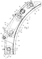
- closing device 9 also comprises a number of hydraulic cylinders 19 equally spaced about the periphery of casing 5 (Fig.s 1 and 2) and connected integral with flange 12 (Fig.3).
- each cylinder 19 comprises a casing 20, one end wall 21 of which is connected integral with the lower surface of flange 12, and the opposite end wall 22 of which presents an axial through hole 23 engaged in sliding manner by the body 24 of a piston 25 mounted so as to slide in fluidtight manner inside casing 20 and towards wall 22 against the thrust exerted by a spring 26 compressed between piston 25 and wall 22.
- the lateral wall 27 of casing 20 houses the end of an output conduit 28 forming part of a hydraulic circuit 29 supplying pressurized fluid to cylinder 19 and over piston 25.
- Circuit 29 comprises a tank 30; a delivery pump 30a connected at one end to tank 30 and at the other to conduit 28 via a calibrated valve 31 for draining fluid into tank 30 when the pressure inside circuit 29 exceeds a given value; and a drain conduit 32 connecting conduit 28 to tank 30 via valve 33.
- Piston 25 presents an axial through hole 34, the bottom end of which is fitted inside with an internally-threaded flanged coupling 35 connected adjustably to the threaded end portion 36 of a rod 37 extending along hole 34.
- Coupling 35 and threaded portion 36 combine to form a regulating device 38 for regulating the axial position of rod 37.
- Each rod 37 extends through a hole 39 in wall 21 and a hole 40 in flange 12 and, when half casings 7 and 8 are closed, engages a respective opening 41 formed through ring 18 and substantially coaxial with holes 39 and 40, and terminates, over ring 18, in a larger-diameter head 42.
- each opening 41 presents an elongated shape, along the circumference of ring 18, defined by a first circular portion 43 of at least the same diameter as head 42, and a second elongated portion 44 extending radially from portion 43 and at least as wide as the diameter of rod 37 but narrower than the diameter of head 42.
- closing device 9 comprises an actuating device indicated as whole by 45 and designed to turn ring 18 in relation to top half casing 8 and, consequently, bottom half casing 7.
- Actuating device 45 comprises a hydraulic actuator 46, the body 47 of which pivots at 48 on one end of a bracket 49 integral with wall 13, so as to turn in relation to half casing 8 about a vertical axis parallel to rods 37; and the output rod 50 of which is connected to a fork 51 extending upwards from the upper surface of ring 18 and integral with ring 18 itself.
- actuating device 45 is so arranged as to maintain ring 18 in a first angular position (Fig.1) in relation to half casing 8 and wherein rods 37 are coaxial with the first portion 43 of respective openings 41, and heads 42 are allowed to slide freely along respective openings 41 and out over ring 18.
- actuating device 45 is operated so as to move ring 18 (clockwise in Fig.s 1 and 2) into a second position (Fig.2) wherein rods 37 engage portion 44 of respective openings 41. Consequently, when pressurized fluid is fed into cylinders 19 up to a given operating pressure, heads 42 press against ring 18 so as to lock half molds 2 and 3 together to a given pressure along plane 4.
- closing device 9 provides not only for troublefree, automatic closure of curing mold 1, but also for maintaining the pressure inside mold 1 substantially constant.
- an increase in pressure inside mold 1 is accompanied immediately by an increase in pressure inside cylinders 19 and circuits 29, the calibrated valves 31 of which provide for automatically limiting stress inside mold 1.
- Fig.s 4 to 7 relate to a closing device 52 which differs from device 9 by comprising, in place of ring 18, a flange element consisting of a double annular flange 53 coaxial with and facing flange 12 and integral with wall 13. Openings 41 on device 9 are replaced by openings 54 formed through flange 53 and each, when viewed from above (Fig.s 4 and 5), being of elongated shape arranged, in the example shown, with its longitudinal axis 55 extending along the circumference of flange 53.
- heads 42 of device 9 are replaced by the same number of heads 56, each fitted on to the top end of a respective rod 37 and being, when viewed from above, of the same elongated shape as respective opening 54, with a longitudinal axis 57.
- adjusting device 38 is dispensed with, and each rod 37 is connected integral with a respective piston 25, and presents, at the bottom end, an axial dead hole 58 connecting rod 37 to an actuating device 59 comprising a reversible motor 60 coaxial with rod 37 and connected integral with structure 6 via a bracket 61.
- Motor 60 presents a rotary output shaft 62 engaging hole 58 and connected angularly to rod 37 via a splined joint 63, so as to turn rod 37 substantially 90° between a first position wherein axes 57 and 55 coincide, and a second position wherein axis 57 is perpendicular to axis 55.
- rods 37 are arranged in said first position, so as to enable heads 56 to slide freely along respective openings 54 and out over flange 53.
- motors 60 are operated so as to move rods 37 and respective heads 56 into said second angular position prior to feeding pressurized fluid inside cylinders 19.
- cylinders 19 are spring-return single-acting cylinders, but these may of course be replaced by double-acting cylinders (not shown).
Landscapes
- Engineering & Computer Science (AREA)
- Mechanical Engineering (AREA)
- Moulds For Moulding Plastics Or The Like (AREA)
- Heating, Cooling, Or Curing Plastics Or The Like In General (AREA)
Applications Claiming Priority (2)
| Application Number | Priority Date | Filing Date | Title |
|---|---|---|---|
| IT67953A IT1241326B (it) | 1990-11-30 | 1990-11-30 | Dispositivo di chiusura per uno stampo di vulcanizzazione di pneumatici |
| IT6795390 | 1990-11-30 |
Publications (1)
| Publication Number | Publication Date |
|---|---|
| EP0488261A1 true EP0488261A1 (de) | 1992-06-03 |
Family
ID=11306672
Family Applications (1)
| Application Number | Title | Priority Date | Filing Date |
|---|---|---|---|
| EP91120341A Withdrawn EP0488261A1 (de) | 1990-11-30 | 1991-11-27 | Schliessvorrichtung für eine Reifenvulkanisierform |
Country Status (4)
| Country | Link |
|---|---|
| US (1) | US5186953A (de) |
| EP (1) | EP0488261A1 (de) |
| JP (1) | JPH06339928A (de) |
| IT (1) | IT1241326B (de) |
Cited By (3)
| Publication number | Priority date | Publication date | Assignee | Title |
|---|---|---|---|---|
| WO1998019849A1 (de) * | 1996-11-07 | 1998-05-14 | Optimel Schmelzgusstechnik Gmbh & Co. Kg | Vorrichtung zum verriegeln und öffnen eines spritzgusswerkzeuges |
| WO2004016414A3 (en) * | 2002-08-16 | 2004-08-26 | John R Cole | An apparatus and method for locking a tire vulcanizing press |
| WO2012065640A1 (de) * | 2010-11-17 | 2012-05-24 | Inauen Group Ag | Vakuumverpackungsmaschine |
Families Citing this family (5)
| Publication number | Priority date | Publication date | Assignee | Title |
|---|---|---|---|---|
| JP2882702B2 (ja) * | 1991-05-20 | 1999-04-12 | 株式会社神戸製鋼所 | タイヤ加硫機の金型クランプ装置 |
| US5447424A (en) * | 1993-10-29 | 1995-09-05 | National Feedscrew & Machining, Ind. Inc. | Cross beam lock for tire press |
| US6702566B1 (en) * | 2001-05-24 | 2004-03-09 | Masco Corporation | Lock assembly for a low pressure mold |
| CN100553924C (zh) * | 2006-01-18 | 2009-10-28 | 鸿富锦精密工业(深圳)有限公司 | 光学元件成型模具 |
| WO2014098276A1 (ko) * | 2012-12-18 | 2014-06-26 | 한국항공우주연구원 | 케이싱 트리트먼트를 활용한 축류 압축기의 스톨 억제 장치 |
Citations (3)
| Publication number | Priority date | Publication date | Assignee | Title |
|---|---|---|---|---|
| US3918861A (en) * | 1974-10-11 | 1975-11-11 | Cooper Tire & Rubber Co | Vulcanizing press with rotary locking mechanism |
| US4601648A (en) * | 1985-09-09 | 1986-07-22 | Kabushiki Kaisha Kobe Seiko Sho | Mold clamp mechanism for tire press |
| GB2199531A (en) * | 1987-01-07 | 1988-07-13 | Mitsubishi Heavy Ind Ltd | Tire vulcanizing machine |
Family Cites Families (5)
| Publication number | Priority date | Publication date | Assignee | Title |
|---|---|---|---|---|
| US3154814A (en) * | 1963-04-30 | 1964-11-03 | Super Mold Corp | Tire curing apparatus |
| JPS57140142A (en) * | 1981-02-26 | 1982-08-30 | Kobe Steel Ltd | Tire-vulcanizing press |
| JPS57140139A (en) * | 1981-02-26 | 1982-08-30 | Kobe Steel Ltd | Tire-vulcanizing press |
| JPS58102742A (ja) * | 1981-12-14 | 1983-06-18 | Kobe Steel Ltd | タイヤ加硫機 |
| JPS5916733A (ja) * | 1982-07-12 | 1984-01-27 | Sumitomo Rubber Ind Ltd | タイヤ加硫機における金型締付力の制御方法 |
-
1990
- 1990-11-30 IT IT67953A patent/IT1241326B/it active IP Right Grant
-
1991
- 1991-10-09 US US07/774,758 patent/US5186953A/en not_active Expired - Lifetime
- 1991-11-27 EP EP91120341A patent/EP0488261A1/de not_active Withdrawn
- 1991-11-29 JP JP3339308A patent/JPH06339928A/ja active Pending
Patent Citations (3)
| Publication number | Priority date | Publication date | Assignee | Title |
|---|---|---|---|---|
| US3918861A (en) * | 1974-10-11 | 1975-11-11 | Cooper Tire & Rubber Co | Vulcanizing press with rotary locking mechanism |
| US4601648A (en) * | 1985-09-09 | 1986-07-22 | Kabushiki Kaisha Kobe Seiko Sho | Mold clamp mechanism for tire press |
| GB2199531A (en) * | 1987-01-07 | 1988-07-13 | Mitsubishi Heavy Ind Ltd | Tire vulcanizing machine |
Non-Patent Citations (3)
| Title |
|---|
| PATENT ABSTRACTS OF JAPAN vol. 6, no. 242 (M-175)(1120) 30 November 1982 & JP-A-57 140 142 ( KOBE SEIKOSHO K.K. ) 30 August 1982 * |
| PATENT ABSTRACTS OF JAPAN vol. 7, no. 203 (M-241)(1348) 8 September 1983 & JP-A-58 102 742 ( KOBE SEIKOSHO K.K. ) 18 June 1983 * |
| PATENT ABSTRACTS OF JAPAN vol. 8, no. 104 (M-296)(1541) 16 May 1984 & JP-A-59 016 733 ( SUMITOMO GOMU K.K.K. ) 27 January 1984 * |
Cited By (9)
| Publication number | Priority date | Publication date | Assignee | Title |
|---|---|---|---|---|
| WO1998019849A1 (de) * | 1996-11-07 | 1998-05-14 | Optimel Schmelzgusstechnik Gmbh & Co. Kg | Vorrichtung zum verriegeln und öffnen eines spritzgusswerkzeuges |
| US6220848B1 (en) | 1996-11-07 | 2001-04-24 | Optimel Schmelzgusstecgnik Gmbh & Co. Kg | Injection moulding die locking and opening device |
| WO2004016414A3 (en) * | 2002-08-16 | 2004-08-26 | John R Cole | An apparatus and method for locking a tire vulcanizing press |
| US6908584B2 (en) | 2002-08-16 | 2005-06-21 | John R. Cole | Apparatus and method for locking a tire vulcanizing press |
| US6981857B2 (en) | 2002-08-16 | 2006-01-03 | Cole John R | Apparatus and method for locking a tire vulcanizing press |
| US7320580B2 (en) | 2002-08-16 | 2008-01-22 | Cole John R | Apparatus and method for loading and unloading a tire press |
| US7442335B2 (en) | 2002-08-16 | 2008-10-28 | Cole John R | Apparatus and method for loading and unloading a tire press |
| HRP20050150B1 (hr) * | 2002-08-16 | 2013-03-31 | John R. Cole | Sprave i metode za zabravljivanje preše za vulkaniziranje gume |
| WO2012065640A1 (de) * | 2010-11-17 | 2012-05-24 | Inauen Group Ag | Vakuumverpackungsmaschine |
Also Published As
| Publication number | Publication date |
|---|---|
| US5186953A (en) | 1993-02-16 |
| IT1241326B (it) | 1994-01-10 |
| IT9067953A0 (it) | 1990-11-30 |
| IT9067953A1 (it) | 1992-05-30 |
| JPH06339928A (ja) | 1994-12-13 |
Similar Documents
| Publication | Publication Date | Title |
|---|---|---|
| KR0163054B1 (ko) | 피결합 밸브 모듈러 제어 패널 | |
| US6041804A (en) | Subsea valve actuator and method | |
| US5186953A (en) | Closing device for a tire curing mold | |
| US4491154A (en) | Double acting pilot valve | |
| US7699355B2 (en) | Variable-angle tubular connection | |
| US5392807A (en) | Fluid pressure actuated flow control valve | |
| US4653256A (en) | Apparatus for establishing reel-to-bedknife clearance | |
| US5060723A (en) | Wellhead isolation tool nipple | |
| DE2751946A1 (de) | Druckmittelverteiler, insbesondere fuer hydraulische fernsteuerungen | |
| CA1301715C (en) | Extensible cylinder and piston unit | |
| US9500294B2 (en) | Hybrid manual and hydraulic actuator override | |
| KR100229344B1 (ko) | 높이제어밸브 및 이를 위한 덤프밸브 | |
| US5918756A (en) | Vessel lock down system | |
| EP0205310B1 (de) | Auspuffbremse | |
| US20190040973A1 (en) | Compound express actuator connection | |
| US4300750A (en) | Position indicating valves | |
| WO1994021949A1 (en) | Self-actuating control valve | |
| US5437216A (en) | Universal hydraulic valve | |
| US4103699A (en) | Fluid cylinder mounted lock out valve device | |
| CA2749508C (en) | Adjustable piston actuator | |
| JPS6120726B2 (de) | ||
| GB2091385A (en) | Lubricated split plug valve | |
| EP0122247A1 (de) | Steuerventil | |
| US4340237A (en) | Lifting and steering system for a vehicle and a vehicle using the same | |
| CN217056478U (zh) | 一种温度压力释放阀 |
Legal Events
| Date | Code | Title | Description |
|---|---|---|---|
| PUAI | Public reference made under article 153(3) epc to a published international application that has entered the european phase |
Free format text: ORIGINAL CODE: 0009012 |
|
| AK | Designated contracting states |
Kind code of ref document: A1 Designated state(s): DE ES FR GB IT |
|
| 17P | Request for examination filed |
Effective date: 19921102 |
|
| 17Q | First examination report despatched |
Effective date: 19940415 |
|
| 18D | Application deemed to be withdrawn |
Effective date: 19960131 |
|
| STAA | Information on the status of an ep patent application or granted ep patent |
Free format text: STATUS: THE APPLICATION IS DEEMED TO BE WITHDRAWN |
|
| R18D | Application deemed to be withdrawn (corrected) |
Effective date: 19960402 |