EP0488330B1 - Lampe fluorescente - Google Patents
Lampe fluorescente Download PDFInfo
- Publication number
- EP0488330B1 EP0488330B1 EP91120454A EP91120454A EP0488330B1 EP 0488330 B1 EP0488330 B1 EP 0488330B1 EP 91120454 A EP91120454 A EP 91120454A EP 91120454 A EP91120454 A EP 91120454A EP 0488330 B1 EP0488330 B1 EP 0488330B1
- Authority
- EP
- European Patent Office
- Prior art keywords
- phosphor
- glass tube
- light transmission
- gas
- transmission glass
- Prior art date
- Legal status (The legal status is an assumption and is not a legal conclusion. Google has not performed a legal analysis and makes no representation as to the accuracy of the status listed.)
- Expired - Lifetime
Links
Images



Classifications
-
- H—ELECTRICITY
- H01—ELECTRIC ELEMENTS
- H01J—ELECTRIC DISCHARGE TUBES OR DISCHARGE LAMPS
- H01J61/00—Gas-discharge or vapour-discharge lamps
- H01J61/02—Details
- H01J61/38—Devices for influencing the colour or wavelength of the light
- H01J61/42—Devices for influencing the colour or wavelength of the light by transforming the wavelength of the light by luminescence
- H01J61/46—Devices characterised by the binder or other non-luminescent constituent of the luminescent material, e.g. for obtaining desired pouring or drying properties
-
- C—CHEMISTRY; METALLURGY
- C09—DYES; PAINTS; POLISHES; NATURAL RESINS; ADHESIVES; COMPOSITIONS NOT OTHERWISE PROVIDED FOR; APPLICATIONS OF MATERIALS NOT OTHERWISE PROVIDED FOR
- C09K—MATERIALS FOR MISCELLANEOUS APPLICATIONS, NOT PROVIDED FOR ELSEWHERE
- C09K11/00—Luminescent materials, e.g. electroluminescent or chemiluminescent
- C09K11/02—Use of particular materials as binders, particle coatings or suspension media therefor
- C09K11/025—Use of particular materials as binders, particle coatings or suspension media therefor non-luminescent particle coatings or suspension media
-
- H—ELECTRICITY
- H01—ELECTRIC ELEMENTS
- H01J—ELECTRIC DISCHARGE TUBES OR DISCHARGE LAMPS
- H01J61/00—Gas-discharge or vapour-discharge lamps
- H01J61/02—Details
- H01J61/38—Devices for influencing the colour or wavelength of the light
- H01J61/42—Devices for influencing the colour or wavelength of the light by transforming the wavelength of the light by luminescence
- H01J61/44—Devices characterised by the luminescent material
Definitions
- the present invention relates to a fluorescent lamp capable of reducing the occurrence of blackening smaller in the rate of lowering luminous flux, while the lamp is in use for long period, and rapid rising of luminous flux at starting stage of lighting.
- the fluorescent lamp is widely used as light sources for common illuminations, office automation machines, and light-emitting elements of the giant screen color display apparatus and also as back lights for liquid crystal displays.
- the reason why it is so widely used in various fields resides in that the electric power supplied can be converted into radiation with extremely high efficiency.
- This fluorescent lamp is arranged so that filling gas including mercury and one or two or more rare gases are filled in a glass tube on whose inner face a fluorescent layer is coated and that positive column discharge is generated in the filling gas.
- the positive column discharge can be usually kept generating by supplying electric energy to the filling gas through two electrodes.
- Mainly ultraviolet rays are generated by this discharge and most of them have wavelengths of 185 nm and 254 nm.
- the indensity ratio of the 185 nm light to 254 nm light is usually in a range of 0.2 - 0.4.
- These ultraviolet lights are converted into radiation which has longer wavelengths by the fluorescent layer on the inner face of the glass tube. These wavelengths depend upon the kind of phosphor particles contained in the phosphor layer and they range from those of near ultraviolet lights to those of visible lights and even those of near infrared lights.
- the most popular low fluorescent lamp is of 40W type shaped like a straight glass tube having a length of 1200 mm and an inner diameter of about 37 mm.
- the inner wall of this lamp is about 300W/m 2 . Note that "inner wall load” defines a consumptive power per unit area of the inner face.
- the glass tube can be variously shaped like a circle, a letter U and a saddle in addition to like the straight line.
- the fluorescent lamps have been made smaller and smaller in size, most of their glass tubes have been shaped in various complicated forms.
- the three components type white-emitting fluorescent lamp in which blue, green and red emitting phosphors each having a relatively narrow band emission spectrum distribution are used has become more and more popular.
- the characteristics of the green emitting phosphor is important because luminous ratio of the green component to the white luminous flux (or output) of the lamp is the highest among the three color components.
- Japanese Patent Disclosure Sho 54-42874 discloses a lamp wherein phosphor particles whose positive ions have the elemental electronegativity values lower than 1.4 are used to form the phosphor layer which has a low luminous flux lowering rate.
- the single measure disclosed in this reference is not enough to prevent luminous flux from being lowered and the lamp from being blackened.
- Blackening of the fluorescent lamp have been considered to be caused by the following factors. Firstly the phosphor itself is deteriorated. The reasons are supposed to reside in that color center is formed in the phosphor by vacuum ultraviolet rays produced by the positive column discharge and that the surface structure of the phosphor layer is changed by the colliding of Hg ions at the surface of the phosphor layer. Secondly, the glass tube is black ended or colored by impurities and reaction products in it. This is supposed to reside in that oxides of filament and cathode matters, compounds caused by residues of organic binders, and/or mercury and mercury compounds contained in the filling gas adhere to the phosphor layer.
- the inner surface of the glass tube is preferably coated with 99.9-94 weight % of the fluorescent material as mentioned above and 0.1-6 weight % of a substance having contact charge more positive than titanium oxide received no surface treatment which is selected from alumina and magnesia.
- JP-A-54 012 260 discloses a screen of a colour picture tube which comprises phosphor material particles coated with 0.02-0.2 m ⁇ thick zinc oxide film.
- the zinc oxide has a high electric conductivity, the production of charge-up phenomenon which is caused by irradiating the phosphor materials with electron beam can be effectively prevented.
- the zinc oxide film serves as green light emitting phosphor. So, green light emission is enhanced by the presence of the zinc oxide film.
- the phosphor particles having average particle size of 5-15 m ⁇ are coated with zinc oxide particles having an average particle size of 0.1-0.5 m ⁇ .
- the conventional fluorescent lamp which has a relatively high inner wall load has advantages of being made small and compact in size, but it has such drawbacks that its luminous efficiency is lower, that its blackening is liable to be caused earlier, that its luminous flux lowering rate is higher, and that the rising of its luminous flux is slower. In addition, these drawbacks are not caused in the same way and it is difficult for the lamps thus produced to have the same quality.
- the reason why the rising of luminous flux is slow is supposed to be caused by the mercury adsorption to the phosphor. Particularly when the inner wall load of the lamp becomes high, the probability that mercury ions are re-bonded with electrons to become mercury atoms at the surface of the phosphor particles become high as electric current density is increased. The mercury atoms are liable to be adsorbed onto the phosphor layer when the lamp is turned off as well as when it is turned on. When it is again turned on, this mercury adsorbed is firstly disrobed. Mercury cohering to the coolest part of the lamp so then gradually vaporized and luminous flux rises depending upon the vapor pressure of the mercury in the glass tube. Fig.
- a curve (A) represents the rising of luminous flux in the case of the fluorescent lamp of 40W which has a relatively low inner tube wall load and which is shaped like a straight tube and another curve (B) that of luminous flux in the case of the fluorescent lamp in which the three component bands emitting phosphor is used and whose inner wall load is larger than 500W/m 2 .
- a part (x) denotes the time at which mercury adsorbed on the phosphor layer is adsorbed and another part (y) the time at which mercury cohering to the coolest part of the lamp is gradually vaporized.
- the present invention is intended to eliminate the above-mentioned drawbacks and the object of the present invention is therefore to provide a fluorescent lamp having low rate of lowering luminous flux capable of preventing the occurrence of blackening, and rapid rising of luminous flux at starting stage of lighting operation although having a high tube wall load.
- a fluorescent lamp 13 comprising:
- a fluorescent lamp 13 comprising:
- a fluorescent lamp 13 comprising a light transmission glass tube 21;
- the adhering of mercury and its compounds to the phosphor layer which is the cause of blackening the fluorescent lamp, can be reduced with a higher reliability and reproducibility.
- the rising characteristic of luminous flux at starting stage operation can be improved with a more easiness and a higher reproducibility and the rate of lowering luminous flux during long operation can be made lower.
- This lamp is most suitable for one smaller in size and having a high inner wall load, and its industrial value is extremely higher.
- the fluorescent lamp of the present invention is provided according to three aspects.
- the fluorescent lamp according to the second aspect of the present invention comprises a light transmission glass tube in which filling gases including mercury and rare gas are filled, a phosphor layer coated on the inner wall of the light transmission glass tube and including phosphor particles, and a means for keeping positive column discharge generating in the filling gases, wherein the phosphor particles are those which are charged or electrified by positive charge smaller than 3.0 ⁇ C per gram when they are in contact soda lime glass beads whose particle size is in a range of 200 - 500 ⁇ m.
- the fluorescent lamp according to the third aspect of the present invention comprises a light transmission glass tube in which filling gases including mercury and rare gas are filled, a phosphor layer coated on the inner wall of the light transmission glass tube and including phosphor particles, and a means for keeping positive column discharge generating in the filling gases, wherein the phosphor particles are those which are charged by charge more positive than -0.5 ⁇ C per gram when they are in contact with reduced iron powder whose particle size is in a range of 44 - 74 ⁇ m.
- the surface of the phosphor particles is coated with a metal oxide including oxide of at least one metal selected from the group consisting of Mg, Ca, Sr, Ba, Zn, Al, Ga, Y, rare earths B, P, Ta, Ti and Si in an amount of 0.01 to 5.0 % by weight, to have and keep the above-mentiond charge.
- a metal oxide including oxide of at least one metal selected from the group consisting of Mg, Ca, Sr, Ba, Zn, Al, Ga, Y, rare earths B, P, Ta, Ti and Si in an amount of 0.01 to 5.0 % by weight, to have and keep the above-mentiond charge.
- the fluorescent lamp of the present invention is extremely effective when it is of the high tube wall load type in which the inner wall load ranges from 500W/m 2 to 2000W/m 2 .
- a contact electrification series is obtained according to charging tendencies of materials, ranking a material which is positively charged against any materials at the top and a material which is negatively charged relative to any material at the bottom.
- Zn 2 SiO 4 :Mn managanese-activated zinc silicate phosphor
- Zn 2 SiO 4 :Mn managanese-activated zinc silicate phosphor
- Hg O mercury filled in the light transmission glass tube reacts with impurity gas as CO 2 emitted from the component in the lamp to become Hg O . It has been found that this HgO which is a mercury compound tends to be more positively charged than Zn 2 SiO 4 :Mn.
- the atomic ratio of ZnO to SiO 2 in Zn 2 SiO 4 :Mn is 2 : 1 in stoichiometry composition, but in the commercial phosphors it is hardly 2 : 1 and the value of ZnO relative to SiO 2 is often in a range of 1.5 - 2.2.
- the phosphor Zn 2 SiO 4 :Mn is strongly negatively charged, as described above, and when the compositional ratio of ZnO relative to SiO 2 is smaller than 2.0, the negative-charging tendency of the phosphor becomes stronger. When it is larger than 2.0, however, this tendency becomes weaker. It has been therefore found that it is difficult to judge the charge characteristic of a phosphor from its chemical formula. In addition to this deviation from the stoichiometry composition, various factors are present to make it difficult to judge the charge characteristic of phosphors.
- phosphor particles have a charging tendency more negative than metal oxides each having a metal ion electronegativity of 7.0 but more positive than metal oxides each having a metal ion electronegativity of 11.8.
- phosphor particles whose charge amount per gram is found smaller than 3.0 ⁇ C measured by the Faraday cage of the blow-off powder charge measuring device when they are in contact with soda lime glass beads whose particle size is in a range of 200 - 500 ⁇ m, or those whose charge amount per gram is found more positive than -0.5 ⁇ C when they are in contact with reduced iron powder whose particle size is in a range of 44 - 74 ⁇ m are used, so that the occurrence of blackening can be suppressed with higher reliability and reproducibility.
- the charge characteristic (or charging tendency of phosphor particles which form the phosphor layer is measured as follows in the case of the present invention.
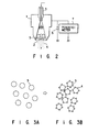
- Fig. 2 schematically shows the structure of the Faraday cage of the blow-off powder charge measuring device.
- the Faraday cage 1 is made of conductive material and a wire mesh filter 2 (Taylor No. 400-mesh stainless steel net) is attached to one end of the cage 1 while a nozzle 3 is attached to the other end thereof.
- a capacitor 6 and an electrometer 7 are connected to the Faraday cage 1.
- a mixture of sample powder 4 whose particle size is smaller than aperture size of the wire net 2 and carrier powder 5 whose particle size is larger than aperture size of the wire mesh 2 is contained in the Faraday cage 1. When compressed gas (or nitrogen gas, for example) is blown for this mixture through the nozzle 3, only the sample powder 4 is blown off outside the cage 1 through the wire mesh 2.
- Powder that does not pass through the 400-mesh is usually used as the carrier powder 5.
- Carrier or soda lime glass beads which had a particle particle size too large to pass through the 200-mesh filter was used in this case.
- Phosphor particles or powder which had a particle size small enough to pass through the 400-mesh were used as the sample powder 4.
- Carrier powder of 20g and phosphor powder of 0.2 g are accurately measured by the chemical balance, transferred into an agate mortar, and well mixed by soft hand blending pestle. This mixture is transferred into a wide-mouth polyethylene bottle and shaken for five minutes by the shaker for through mixing. 0.2 g of this mixed powder of carrier and sample powders is accurately measured to prepare the sample which is to be used for the blow-off powder charge measurement.
- the stoichiometry composition ratio of this mixed powder in weight is carrier 100 relative to phosphor 1.
- Figs. 3A and 3B show particles of the carrier powder and those of the measuring sample (after it is mixed with the carrier). When the carrier powder 5 shown in Fig. 3A is mixed with the sample powder, the sample powder particles 4 are attached on each of the carrier particles as shown in Fig. 3B.
- FIG. 5 shows the relation between charge amount and particle size in a case where Y 2 O 3 :Eu phosphor is used as the sample powder. As shown in Fig. 5, it can be understood that the charge amount of the phosphor depends largely its particle size even when the phosphor composition is not charged.
- Phosphor (Chemical Formula): Charge ( ⁇ C/g) 1 BaMg 2 Al 16 O 27 :Eu 2+ 1.5 2 (Sr,Ca) 10 (PO 4 ) 6 Cl 2 :Eu 2+ 1.8 3 (Sr,Ca,Ba) 10 (PO 4 ) 6 Cl 2 :Eu 2+ 1.6 4 (Ba,Ca,Mg) 10 (PO 4 ) 6 Cl 2 :Eu 2+ 1.2 5 La 2 O 3 ⁇ 0.2SiO 2 ⁇ 0.9P 2 O 5 :Ce,Tb 0.7 6 (La,Ce,Tb)PO 4 0.8 7 Y 2 SiO 5 :Ce,Tb -0.5 8 (Ce,Mg)Al 11 O 19 :Tb 1.1 9 Zn 2 SiO 4 :Mn -2.8 10 Y 2 O 3 :Eu 3+ 2.0 11 YVO 4 :Eu 3+ -1.5 12 Y(P,V)O 4 :Eu 3+ 1.4 13 Y
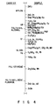
- Fig. 6 shows the charging tendencies of simple oxides including HgO. This result was obtained by using the blow-off powder charge measuring device (see Journal Of Electrochemical Society; Page 842, Volume 133 (1986)). The product of the charge amount of each of the particulate oxides, same in particle size, relative to iron powder, and the specific gravity of each of them is plotted on the vertical axis in Fig. 6. Values of their charge amounts shown are large accordingly.
- the charge amounts measured as described above have extremely good interrelation to electronegativities X i of metal ions which form the oxides, and the oxides tend to be charged more positive as X i becomes smaller while more negative as X i becomes larger.
- X i (1 + 2Z) X O
- Z represents the ion valence of metal ion
- X O be notes the Pauling's electronegativity.
- HgO has substantially the same charging tendency as those of Y 2 O 3 . It is therefore supposed that HgO is difficult to be adsorbed onto those phosphors whose main component is Y 2 O 3 . On the contrary, it is difficult for HgO to be adsorbed onto those phosphor particles whose charging tendency is largely different or remote from that of HgO. It was therefore experimentally confirmed how much difference in charging tendency was allowed from that of HgO for manufacturing the fluorescent lamps with good performance. It was thus found that the occurrence of blackening could be suppressed when those phosphor particles whose charge amount measured according to the above-mentioned measuring manner were smaller than 3 ⁇ C/g were used. When the charge amount of phosphor particles becomes larger than 3 ⁇ C/g, its difference from that of HgO becomes too large and the possibility of blackening becomes high. More preferable charge amount is in range of 0.5 - 2.5 ⁇ C/g.
- Charge amounts of various phosphor particles were measured in the above case using, as the carrier, the glass beads each having a predetermined particle size, but same charging tendency was found in a case where reduced iron powder each particle having a particle size of 44 - 74 ⁇ m was used as the carrier.
- Preferable charge in this case is in a range of -0.5 - 2.5 ⁇ C/g.
- Charging tendency which does not depend on the particle size can be determined as follows. First charging tendencies of metal plates can be examined basing on those of the oxide particles. The metal plate is tilted from the horizontal plane by about 45 degrees, particles of each of the oxides are rolled over the slope of this metal plate and they are received in a Faraday cage type receptacle. The charge polarity of the particles is checked in a receptacle to which an electrometer and a capacitor are connected. When oxide A shows positive polarity against type plate and oxide B shows negative polarity against the plate, the charging tendency of the plate lies between those of A and B. The charging tendency position among those of oxides can be correctly determined by using this procedure successively with various oxides.
- the charging tendency positions thus obtained of metal plates such as nickel, chromium and tantalum are also shown in Fig. 6.
- the metal plates whose charging tendency positions have been determined in this manner are tilted, particles of each of the phosphors are rolled over the slopes of these metal plate and their charge polarities are checked in the receptacle. Their charging tendencies relative to that of the metal plates can be thus obtained. From these charging tendencies of metal oxides, metals and phosphors which are obtained as described above, it can be indirectly understood what relation exists in the charging tendencies of mercury oxides and phosphors. Even in the case of phosphor particles whose particle size is different from those of the others, therefore their charging tendency can be compared using Fig. 6.
- the charge amount of 0.5 - 2.5 ⁇ C/g obtained by the blow-off powder charge measuring device in the case where each of the phosphor particles has the particle size of 5 + 2 ⁇ m and the glass glass beads each having a certain particle size is used as the carrier, means in Fig. 6 such a charging tendency that is positioned more positive than that of metal tantalum but more negative than that of nickel.
- this charging tendency is expressed in the form of the metal ion electronegativity, it is in a range of 7.0 - 11.8. It is therefore important that the charging tendency of phosphor particles is positioned more negative than that of metal oxides each having the metal ion electronegativity of 7.0 but more positive than that of metal oxides each having the metal ion electronegativity of 11.8.
- blue emitting phosphors activated by divalent europium such as BaMg 2 Al 16 O 27 Eu 2+ , SR 10 (PO 4 ) 6 Cl 2 :Eu 2+ , (Sr, Ca) 10 (PO 4 ) 6 Cl 2 :Eu 2+ , (Sr, Ca, Ba) 10 (PO 4 ) 6 Cl 2 :Eu 2+ and (Ba, Ca, Mg) 10 (PO 4 ) 6 Cl 2 :Eu 2+ ; green emitting phosphors such as La 2 O 3 0.2siO 2 0.9P 2 O 5 :Ce,Tb, LaPO 4 :Ce,Tb, Y 2 SiO 5 : Ce,Tb, CeMgAl 11 O 19 :Tb, and Zn 2 SiO 4 :Mn, red emitting phosphors activated by trivalent europium such as Y 2 O 3
- the charge characteristics of phosphors can be controlled in the scope of the present invention by coating their particle surfaces with those inorganic compounds whose charge characteristics (polarity and charge amount) are similar to those of HgO, that is, oxides such as Al 2 0 3 and alkali rare-earth metal compounds such as Ca 2 P 2 O 7 , Sr 2 P 2 O 7 and Ba 2 P 2 O 7 .
- the weight percent of each of the inorganic compounds contained in the phosphor is in a range of 0.01 - 5.0, preferably 0.01 - 3.0. It is because the effect of controlling the charging tendency of the phosphor is not sufficient when the amount of the inorganic compound attached to the phosphor particles is smaller than 0.01 weight% and because the luminous efficiency of the phosphor is lowered when it exceeds 5.0 weight%.
- Table 2 shows results obtained by measuring the charge characteristics of phosphors by the blow-off powder charge measuring device, said phosphors being coated (or mixed) with inorganic compounds at their particle surfaces.
- a sample 17 shown in Table 2 is prepared by surface treating the sample 7 shown in Table 1, and a sample 28 shown in Table 2 is prepared by surface-treating the sample 6 shown in Table 1.
- Table 2 it can be understood that the surface-treated phosphors have characteristics different from those phosphors not surface-treated shown in Table 1.
- metal oxide selected from the group of MgO, CaO, SrO, BaO and ZnO is used as the inorganic compound with which the phosphor particles are surface-coated. It is because metal ion electronegativities of these metal oxides are smaller than 7 and their surface charging tendencies are positioned properly more positive side than that of HgO, so that the charging tendency of the surface of the phosphor can be controlled toward more positive side by even a small coating amount, and that the phosphor particles can be prevented from reacting with HgO to more effectively suppress the blackening of lamp.
- the inorganic compound which is used to surface-treat the phosphors is selected by taking into consideration of charging tendency, chemical stability and light absorbability for ultraviolet and light emitted from the phosphors.
- Metal oxides such as alkaline earth elements, rare-earth elements including yttrium, aluminium and gallium each having an electronegativity smaller than 11 are charged positive relative to iron, and other metal oxides such as titanium, tantalum and phosphorus each having an electronegativity large than 11 are charged negative relative to iron. Needless to say, they can be used in the form of a mixture, if total effect of the surface treatment brings the phosphor charging tendency into the proper region and meet to other conditions such as chemical stability etc. as mentioned above.
- the fluorescent lamp particularly of the high load type having an inner wall load of 500 - 2000W/m 2 , is liable to be blackened because mercury and its oxides are adsorbed on the phosphor layer of the lamps, as described above.
- the charging tendency of the surface-treated phosphor particles which form the phosphor layer of the lamp is positioned more negative side than that of metal oxides each having the electronegativity X i of 7.0 but more positive side than that of metal oxides each having the electronegativity Xi of 11.8, these phosphor particles are charged positive and smaller than 3.0 ⁇ C per gram at the time of their contact with the soda lime glass beads each having the particle size of 200 - 500 ⁇ m, and they are charged positive and larger than -0.5 ⁇ C gram at the time of their contact with the reduced iron powder particles each having the particle size of 44 - 74 ⁇ m, therefore, the blackening of the lamp can be suppressed with higher reliability and reproducibility.
- Fluorescent lamps each shaped like a straight tube shown in Fig. 8 were made using the phosphor slurries. As shown in Fig. 8, the slurry including one of the phosphors was coated on the inner wall of each of straight glass tubes 11 and baking and exhausting steps were applied to the glass tubes 11 after they were dried to form a phosphor layer 14 on the inner wall of each of the glass tubes 11. Sealing gases including mercury were then filled in each of the glass tubes 11 and both ends of each of the glass tubes 11 were sealed by caps 12 in which lighting circuits were housed. These glass tubes 11 were then aging-treated.
- Each of the fluorescent lamps thus prepared is so arranged that electrodes (not shown) are attached to both ends of the glass tube 11 and that the phosphor layer 14 in the glass tube 11 is made luminous by absorbing ultraviolet rays generated from mercury excited when predetermined voltage is added to the electrodes through the caps 12.
- Fluorescent lamps 13 of the straight tube type each having an inner wall load of 700W/m 2 , a diameter of 25 mm and a length of 1200 mm were made in this manner. The following evaluation was made for the lamps prepared.
- the lamp blackening due to the adsorption of Hg was evaluated as follows: Those lamps which had no blackening just after their lighting (zero hour) were evaluated as point 10. The lamps which has been lighted for predetermined hours were evaluated over ten step values from practical viewpoints. What the lamps had the blackening just after zero hour means that they had already been blackened before their lighting or at the aging process.
- Results obtained by evaluating the lamp blackening as described above are shown in Table 3.
- the blow-off powder charge measuring device shown in Fig. 2 and the glass beads which served as the carrier were used to measure charge amounts of the phosphors used in the lamps. Results thus obtained are also shown in Table 3.
- Fluorescent lamps 16 each shaped like a letter U as shown in Fig. 9 were made using the same phosphor matters as in Example 1.
- a phosphor layer was formed on the inner wall of each of U-shaped glass tubes 15 in the same way as in Example 1 and filling gases including mercury were filled in the glass tube 15. Both ends of the glass tube 15 were then sealed by the cap 12 in which a lighting circuit was housed.
- the U-shaped fluorescent lamps 16 each having an inner wall load of 1000W/m 2 , a length of 410 mm and diameter of 20 mm were prepared in this manner and the same blackening evaluation and charge amount measurement as in Example 1 were made. Results thus obtained are shown in Table 4.
- Example 1 Same phosphor matters as in Example 1 were used and a phosphor layer was formed on the inner wall of each of curved glass tubes 17 in the same manner as in Example 1.
- Curved fluorescent lamps 18 shown in Fig. 10 were thus prepared. As shown in Fig. 10, each of the curved fluorescent lamps 18 is so arranged that filling gases including mercury are filled in the curved glass tube 17 on the inner wall of which the phosphor layer is formed and that one end of the glass tube 17 is sealed by the cap 12 in which the lighting circuit is housed.
- the fluorescent lamps 18 of the compact type each having an inner wall load of 1500W/m were prepared in this manner and the blackening evaluation was made in the same way as in Example 1.
- numeral 12a represents an electronic lighting circuit
- 12b a power source case
- 12c a heat insulating substrate.
- Comparison Examples 1 - 3 shown in Tables 1 - 3 represent those fluorescent lamps which were made under same conditions as in the above-described Examples, using phosphor matters selected from samples 1 - 13 in Table 1 and samples 16 - 25 in Table 2, said selected phosphor matters having negative charge or being positioned in the electrication (charging) series remote from HgO. Same blackening evaluation and charge amount measurement were made for these Comparison Examples thus prepared.
- magnesium nitrate Mg(NO 3 ) 2
- the phosphor particles thus obtained were surface-coated with MgO colloidal poaricles of 0.3 weight%.
- a 4W fluorescent lamps FL4 (15.5 mm, inner wall load: 1100W/m 2 ) shown in Fig. 8 was made as usual, using the green emitting phosphor. Its initial luminous output, that after it was lighted for 1000 hours and the coloration (blackening) of its phosphor layer were measured and evaluated. Results thus obtained are shown in Table 6.
- the rare earth ulmic alminate-silica-phosphate green emitting phosphor activated by cerium and terbium and used by the above-mentioned Example was used without being coated with any of metal oxides, and the same fluorescent lamp of the straight tube type was prepared. Its characteristics were measured under the same conditions as in the above Example. Both of the initial luminous output and that after 1000-hour lighting thus measured for the surface coated phosphor are shown as relative values when each value of the phosphor without being coated (Comparison Sample) is expressed as 100%. As the blackening of the lamp tube becomes lighter, its evaluation value is taken higher up to its maximum point 10.
- the luminous output after 1000-hour lighting in the case of our Example was 110%, as compared with that of the phosphor without being surface coated (Comparison Sample).
- the blackening of the lamp tube in the case of the Comparison Sample was 6.0 but it was 9.0 in the case of our Example.
- the quality of the lamp according to the invention could be thus improved.
- the initial luminous output was not largely lowered but kept substantially the same as that of the Comparison Sample.
- ZnO zinc oxide
- particle size about 0.05 ⁇ m
- 100g of rare earth silica-borate-phosphate green emitting phosphor activated by cerium and terbium ((La 0.04 Ce 0.45 Tb 0.15 ) 2 O 3 0.001SiO 2 0.988P 2 O 5 0.0005B 2 O 5 ) was then added to the suspension and fully stirred.
- Acryl emulsion 0.1 g and poly acrylic acid ammonium 0.05 g were successively added to it and uniformly dispersed.
- the suspension thus prepared was then filtered by means of suction and a cake-like residue was dried at about 120°C.
- Phosphor-particles thus prepared were surface-coated by colloidal ZnO particles of 1.0 weight%.
- a Comparison Sample shown in Table 6 represents a fluorescent lamp which was made under the same condition as in Example 4 but using the green-emitting phosphor without being coated with any of metal oxide particles. Results shown in Table 6 are obtained for the Comparison Sample thus prepared.
- Green emitting phosphors were prepared in the same manner as in Example 4 while changing the kind of green emitting phosphor as well as the kind and the concentration of that metal oxide by which the green emitting phosphor was to be coated. Using green emitting phosphors thus prepared, fluorescent lamps were made and the same characteristic evaluations were conducted. Results thus obtained are shown in Table 6.
- green emitting phosphors which have the same in composition as those in Examples 4 and 7 were prepared in the way same as in Example 4 but different in that the amount of metal oxide particles attached to the phosphors were set smaller than 0.01 weight% or larger than 3.0 weight%. Fluorescent lamps were made using the green emitting phosphors thus prepared, and the same characteristic evaluations were made about the lamps.
- the lowering of their luminous outputs after their long time lighting can be reduced while keeping their initial luminous outputs substantially the same as those of the conventional ones, and the blackening of the fluorescent lamps can also be suppressed, as apparent from Table 6. Further, it is found that better effect can be achieved when the amount of metal oxides surface-attached to the phosphors is in a range of 0.01 - 1.0 weight%.
- the phosphor was dispersed in solution in which a binding agent such as nitrocellulose was contained to prepare a slurry.
- This slurry including the phosphor was coated to a certain thickness on the inner wall of a straight glass tube having an inner diameter of 10 mm and after it was dried, baking process was applied to it to remove the binder from it.
- Mercury and filling gas were filled in the glass tube and both ends of the glass tube were sealed by caps.
- a fluorescent lamp of the straight tube type having a length of 300 mm between its caps was thus made. The lamp was provided with a small pipe which served as the cooler portion of the lamp to enable excess mercury to condense thereon.
- the luminous flux of the lamp reached its stationary value after about 30 seconds operation since the lamp was lighted.
- the luminous flux after 300-hour lighting measured relative to its initial value (maintenance value) was 90%. This result is shown in Table 7.
- Example 17 0.2 g of zinc hydroxide colloid which was prepared by adding 0.2 mol/l of ammonium solution and 0.1 mol/l of zinc sulfate solution instead of magnesium oxide in Example 17 was surface-attached to the red-emitting yttrium oxide phosphor particles activated by europium. Filtering and drying were applied to it in the same way as in Example 17 and a surface-treated phosphor was thus prepared. The zinc hydroxide colloid was changed to zinc oxide colloid by the drying process.
- Example 17 Silica colloid (OX-50 made by Japan Aerosil Corporation) instead of magnesium oxide colloid in Example 17 was attached to particle surfaces of the yttrium oxide phosphor activated by europium to prepare samples. Using these samples, fluorescent lamps were made in the same manner as in Example 17. Contact charge amounts of the phosphors and characteristics of the fluorescent lamps were evaluated in the same manner as in Example 17. Results thus obtained are shown in Table 7.
- magnesium or zinc oxide was attached to particle surfaces of green emitting zinc silicate phosphor particle activated by manganese and having an average particle size of 5.7 ⁇ m.
- the amount of magnesium oxide or zinc oxide attached was changed as shown in Table 7 in this case.
- fluorescent lamps were made in the same manner as in Example 17 and contact charge amounts of the phosphors and characteristics of the fluorescent lamps were evaluated also in the same manner as in Example 17. Results thus obtained are shown in Table 7.
- Silica colloid was attached to particle surfaces of the green emitting zinc silicate phosphor activated by manganese to prepare a phosphor sample whose contact charge amount against to the iron powder was out of the range of the present invention.
- fluorescent lamps were made in the same way as in Example 17 and contact charge amounts of the phosphors and characteristics of the fluorescent lamps were evaluated also in the same manner as in Example 17. Results thus obtained are shown in Table 7.
- Yttrium oxide activated by europium and charged positive against the iron powder and zinc silicate phosphor activated by manganese and charged negatively against the iron powder were cited as the phosphors used in the above-described Our and Comparison Examples. Further, magnesium oxide and zinc oxide charged positively against the iron powder and silica charged negatively against the iron powder were cited as the surface-attaching metal oxides. It is understood from these Examples that the charging tendency of each of the phosphor can be changed toward that of the surface-attaching metal oxide used or that the charging tendency of each of the phosphors can be controlled by selecting proper kind and amount of the surface-attaching metal oxide used.
- Figs. 13 and 14 show results obtained in the case of (La, Ce, Tb)(P, Si)O 4 and Fig. 14 results obtained in the case of Zn 2 Si0 4 :Mn.
- Fig. 15 shows results obtained in the case of (La, Ce, Tb)(P, Si)O 4
- a fluorescent lamp was made in the same way but using Y 2 O 3 :Eu as the phosphor.
- the relation between luminous flux and lighting time for this lamp after 300-hour life test such a tendency as shown in Fig. 17.
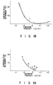
- the luminous flux drops to a point B and then rises to stable point C. It was found that the dropping of the luminous flux decrement from the point A to the point B depends upon the charging tendency of the phosphor.
- Fig. 18 is a graph showing the charge tendency of the phosphor Y 2 O 3 :Eu against the reduced iron powder and the luminous flux decrement. The decrement is expressed as (A - B) + A ⁇ 100%, where A and B means the relative luminous flux at A and B points in Fig. 17, respectively.
- Phosphor particles were prepared to have a certain charging tendency by coating particle surfaces of green-emitting phosphor (La, Ce. Tb)(P, Si)O 4 with 0.1 weight% of MgO.
- a fluorescent lamp having an inner wall load of 750W/m 2 and such structure as shown in Fig. 10 was made using the phosphor Lighting test was conducted for this fluorescent lamp. Its luminous flux rising and other characteristics were improved to a greater extent, as compared with those of the conventional fluorescent lamps.
- Fig. 19 is a graph showing the relation between luminous flux decrement and charging tendency in the case where the fluorescent lamp was made using the phosphor of three component mixture type.
Landscapes
- Chemical & Material Sciences (AREA)
- Engineering & Computer Science (AREA)
- Materials Engineering (AREA)
- Organic Chemistry (AREA)
- Luminescent Compositions (AREA)
Claims (3)
- Lampe fluorescente (13) comportant :caractérisée en ce que les particules de substance fluorescente sont revêtues d'un oxyde métallique contenant un oxyde d'au moins un métal choisi dans le groupe formé de : Mg, Ca, Sr, Ba, Zn, Al, Ga, Y, des terres rares, B, P, Ta, Ti et Si en une quantité de 0,01 à 5,0 % en poids, et en ce que la tendance à se charger des particules de la substance fluorescente est positionnée d'un côté plus négatif que celui des oxydes métalliques, ayant chacune une électronégativité d'ion métallique celle de Xi de 7,0 mais d'un côté plus positif que celui des oxydes métalliques, ayant chacun une électronégativité d'ion métallique Xi de 11,8, avec Xi = (1 + 2z)X0, z représentant une valence ionique d'un ion métallique et X0 représentant une électronégativité de Pauling.un tube de verre laissant passer la lumière (11);une couche de substance fluorescente (14) formée sur la paroi interne du tube de verre laissant passer la lumière (11) et contenant des particules de substance fluorescente rendues lumineuses par des rayons ultraviolets provenant de mercure excité;du gaz introduit dans le tube de verre laissant passer la lumière (11) et contenant un gaz avec du mercure et un gaz rare; etdes moyens, disposés dans le tube de verre laissant passer la lumière (11), destinés à produire une décharge en colonne positive dans le gaz;
- Lampe fluorescente (13) comportant :caractérisée en ce que les particules de substance fluorescente sont revêtues d'un oxyde métallique contenant un oxyde d'au moins un métal choisi dans le groupe formé de : Mg, Ca, Sr, Ba, Zn, Al, Ga, Y, des terres rares, B, P, Ta, Ti et Si en une quantité de 0,01 à 5,0 % en poids et sont chargées positivement et à moins de 3,0 µC par gramme lorsqu'elles sont en contact avec des perles de verre à base de soude et de chaux ayant chacune une dimension de particule de 200 - 500 µm.un tube de verre laissant passer la lumière (11);une couche de substance fluorescente formée sur la paroi interne du tube de verre laissant passer la lumière (11) et contenant des particules de substance fluorescente rendues lumineuses par des rayons ultraviolets provenant de mercure excité;des gaz introduits dans le tube de verre laissant passer la lumière (11) et contenant un gaz avec du mercure et un gaz rare; etdes moyens, disposés dans le tube de verre laissant passer la lumière (11), pour produire une décharge en colonne positive dans le gaz;
- Lampe fluorescente (13) comportant un tube de verre laissant passer la lumière (11);caractérisée en ce que les particules de substance fluorescente sont revêtues d'un oxyde métallique contenant un oxyde d'au moins un métal choisi dans le groupe formé de: Mg, Ca, Sr, Ba, Zn, Al, Ga, Y, des terres rares, B, P, Ta, Ti et Si en une quantité de 0,01 à 5,0 % en poids, et sont chargées positivement et à plus de - 0,5 µC par gramme lorsqu'elles sont en contact avec de la poudre de fer réduit ayant une dimension de particule de 44 - 74 µm.une couche de substance fluorescente (14) formée sur la paroi interne du tube de verre laissant passer la lumière (11) et contenant des particules de substance fluorescente rendues lumineuses par des rayons ultraviolets provenant de mercure excité;du gaz introduit dans le tube de verre laissant passer la lumière (11) et contenant un gaz avec du mercure et un gaz rare; etdes moyens, disposés dans le tube de verre laissant passer la lumière, destinés à produire une décharge en colonne positive dans le gaz;
Applications Claiming Priority (15)
| Application Number | Priority Date | Filing Date | Title |
|---|---|---|---|
| JP32713090 | 1990-11-28 | ||
| JP32713090 | 1990-11-28 | ||
| JP32816790 | 1990-11-28 | ||
| JP328167/90 | 1990-11-28 | ||
| JP327130/90 | 1990-11-28 | ||
| JP32816790 | 1990-11-28 | ||
| JP65739/90 | 1991-01-10 | ||
| JP6573991 | 1991-01-10 | ||
| JP6573990 | 1991-01-10 | ||
| JP9445391 | 1991-04-24 | ||
| JP94453/91 | 1991-04-24 | ||
| JP9445391 | 1991-04-24 | ||
| JP3220637A JP2653576B2 (ja) | 1990-08-31 | 1991-08-30 | 低圧水銀蒸気放電ランプ |
| JP22063791 | 1991-08-30 | ||
| JP220637/91 | 1991-08-30 |
Publications (3)
| Publication Number | Publication Date |
|---|---|
| EP0488330A2 EP0488330A2 (fr) | 1992-06-03 |
| EP0488330A3 EP0488330A3 (en) | 1993-09-01 |
| EP0488330B1 true EP0488330B1 (fr) | 1999-06-09 |
Family
ID=27523926
Family Applications (1)
| Application Number | Title | Priority Date | Filing Date |
|---|---|---|---|
| EP91120454A Expired - Lifetime EP0488330B1 (fr) | 1990-11-28 | 1991-11-28 | Lampe fluorescente |
Country Status (3)
| Country | Link |
|---|---|
| US (1) | US5289081A (fr) |
| EP (1) | EP0488330B1 (fr) |
| DE (1) | DE69131315T2 (fr) |
Cited By (1)
| Publication number | Priority date | Publication date | Assignee | Title |
|---|---|---|---|---|
| CN101322214B (zh) * | 2006-02-23 | 2010-06-02 | 松下电器产业株式会社 | 等离子显示装置以及等离子显示装置用绿色荧光体材料的制造方法 |
Families Citing this family (29)
| Publication number | Priority date | Publication date | Assignee | Title |
|---|---|---|---|---|
| DE69431331T2 (de) * | 1993-07-30 | 2003-06-18 | Kabushiki Kaisha Toshiba, Kawasaki | Lumineszentes Material für Quecksilberentladungslampe |
| JPH07162599A (ja) * | 1993-12-06 | 1995-06-23 | Sony Corp | 画像読取装置 |
| WO1996005265A1 (fr) * | 1994-08-08 | 1996-02-22 | Philips Electronics N.V. | Procede pour appliquer un revetement sur un substrat luminescent |
| JP2746186B2 (ja) * | 1995-04-12 | 1998-04-28 | 双葉電子工業株式会社 | 蛍光体 |
| EP0757376B1 (fr) * | 1995-07-31 | 2001-08-16 | Matsushita Electronics Corporation | Lampe fluorescente et procédé pour sa fabrication |
| US6197218B1 (en) * | 1997-02-24 | 2001-03-06 | Superior Micropowders Llc | Photoluminescent phosphor powders, methods for making phosphor powders and devices incorporating same |
| US6180029B1 (en) | 1997-02-24 | 2001-01-30 | Superior Micropowders Llc | Oxygen-containing phosphor powders, methods for making phosphor powders and devices incorporating same |
| US6057561A (en) * | 1997-03-07 | 2000-05-02 | Japan Science And Technology Corporation | Optical semiconductor element |
| DE19806213B4 (de) * | 1998-02-16 | 2005-12-01 | Tews, Walter, Dipl.-Chem. Dr.rer.nat.habil. | Kompakte Energiesparlampe |
| US6547617B1 (en) * | 1998-07-08 | 2003-04-15 | Hiroyuki Kawamura | Plasma display panel manufacturing method for manufacturing a plasma display panel with superior picture quality, a manufacturing apparatus and a phosphor ink |
| US6911159B2 (en) * | 2000-06-22 | 2005-06-28 | Nite-Glo Innovations Pty Ltd | Phosphorescent pigments |
| US6452324B1 (en) | 2000-08-30 | 2002-09-17 | General Electric Company | Fluorescent lamp for grocery lighting |
| US6525460B1 (en) | 2000-08-30 | 2003-02-25 | General Electric Company | Very high color rendition fluorescent lamps |
| KR100366097B1 (ko) | 2000-09-29 | 2002-12-26 | 삼성에스디아이 주식회사 | 연속박막 형태의 보호층이 코팅된 pdp용 형광체 및 그제조방법 |
| KR100393190B1 (ko) * | 2001-03-06 | 2003-07-31 | 삼성전자주식회사 | 평판형광램프 제조방법 |
| DE10125547A1 (de) * | 2001-05-23 | 2002-11-28 | Philips Corp Intellectual Pty | Flüssigkristallbildschirm mit weißer Lichtquelle |
| US20040076460A1 (en) * | 2002-02-21 | 2004-04-22 | Zen Design Group, Ltd. | Phosphorescent writing system |
| DE10254208A1 (de) * | 2002-11-20 | 2004-06-03 | Patent-Treuhand-Gesellschaft für elektrische Glühlampen mbH | Dielektrische Barriere-Entladungslampe und Verwendung dieser Lampe für die Röntgenbildbetrachtung |
| KR100511757B1 (ko) * | 2003-02-19 | 2005-09-01 | 유재수 | 금속산화물이 코팅된 플라즈마 디스플레이 패널용 형광체의 제조방법 및 그로 제조된 플라즈마 디스플레이 패널용 형광체 |
| JP4207644B2 (ja) * | 2003-04-22 | 2009-01-14 | パナソニック株式会社 | プラズマディスプレイ装置用蛍光体の製造方法 |
| US7268370B2 (en) * | 2003-06-05 | 2007-09-11 | Matsushita Electric Industrial Co., Ltd. | Phosphor, semiconductor light emitting device, and fabrication method thereof |
| JP2005268770A (ja) * | 2004-02-19 | 2005-09-29 | Matsushita Electric Ind Co Ltd | 白色発光素子及び白色光源 |
| KR100904807B1 (ko) * | 2006-02-23 | 2009-06-25 | 파나소닉 주식회사 | 플라즈마 디스플레이 장치 |
| KR100904809B1 (ko) * | 2006-02-23 | 2009-06-25 | 파나소닉 주식회사 | 플라즈마디스플레이장치용 녹색형광체 재료의 제조방법 |
| US8035301B2 (en) * | 2006-02-23 | 2011-10-11 | Panasonic Corporation | Plasma display device and method of manufacturing green phosphor material for plasma display device |
| FR2931143B1 (fr) * | 2008-05-15 | 2011-01-07 | Rhodia Operations | Phosphate de lanthane et d'au moins une terre rare choisie parmi le cerium et le terbium sous forme d'une suspension, procede de preparation et utilisation comme luminophore |
| US20110163657A1 (en) * | 2009-05-25 | 2011-07-07 | Panasonic Corporation | Phosphor, method for producing the same, and light-emitting device |
| CN103805196B (zh) * | 2014-02-27 | 2016-09-28 | 昆山开威电子有限公司 | 一种基于Ce:YAG晶片的复合结构及制作方法 |
| US12031210B2 (en) * | 2020-08-07 | 2024-07-09 | Lawrence Livermore National Security, Llc | System and method for atomic layer deposition of rare-earth oxides on optical grade materials for laser gain media |
Family Cites Families (5)
| Publication number | Priority date | Publication date | Assignee | Title |
|---|---|---|---|---|
| DK480477A (da) * | 1976-11-02 | 1978-05-03 | Philips Nv | Lavtrykskviksoelvdampudladningslampe |
| US4423349A (en) * | 1980-07-16 | 1983-12-27 | Nichia Denshi Kagaku Co., Ltd. | Green fluorescence-emitting material and a fluorescent lamp provided therewith |
| JPS60109164A (ja) * | 1983-11-17 | 1985-06-14 | Toshiba Corp | 蛍光ランプ |
| US4999219A (en) * | 1989-11-07 | 1991-03-12 | Gte Laboratories Incorporated | Method for coating phosphor particles using aluminum isopropoxide precursors and an isothermal fluidized bed |
| JP3149444B2 (ja) * | 1991-01-30 | 2001-03-26 | 東芝ライテック株式会社 | 低圧水銀蒸気放電灯 |
-
1991
- 1991-11-27 US US07/798,727 patent/US5289081A/en not_active Expired - Lifetime
- 1991-11-28 EP EP91120454A patent/EP0488330B1/fr not_active Expired - Lifetime
- 1991-11-28 DE DE69131315T patent/DE69131315T2/de not_active Expired - Lifetime
Cited By (1)
| Publication number | Priority date | Publication date | Assignee | Title |
|---|---|---|---|---|
| CN101322214B (zh) * | 2006-02-23 | 2010-06-02 | 松下电器产业株式会社 | 等离子显示装置以及等离子显示装置用绿色荧光体材料的制造方法 |
Also Published As
| Publication number | Publication date |
|---|---|
| DE69131315D1 (de) | 1999-07-15 |
| EP0488330A2 (fr) | 1992-06-03 |
| DE69131315T2 (de) | 1999-10-28 |
| US5289081A (en) | 1994-02-22 |
| EP0488330A3 (en) | 1993-09-01 |
Similar Documents
| Publication | Publication Date | Title |
|---|---|---|
| EP0488330B1 (fr) | Lampe fluorescente | |
| EP0638625B1 (fr) | Matériau luminescent pour lampe à décharge de mercure | |
| US5518808A (en) | Luminescent materials prepared by coating luminescent compositions onto substrate particles | |
| US5402036A (en) | Low pressure mercury vapor discharge lamp having double layers | |
| JP2000073053A (ja) | 蛍光体及びこの蛍光体を用いた陰極線管 | |
| JP2003013059A (ja) | カラー陰極線管及びそれに用いる赤色蛍光体 | |
| JP2001107045A (ja) | 燐・バナジン酸塩蛍光体およびそれを用いた表示装置並びに発光装置 | |
| JPH0126038Y2 (fr) | ||
| JP2653576B2 (ja) | 低圧水銀蒸気放電ランプ | |
| CN1049000C (zh) | 荧光体及使用该荧光体的荧光灯 | |
| US5386176A (en) | Cathode-ray tube containing an indium borate phosphor | |
| US6150757A (en) | Method of coating a luminescent material | |
| JP3832024B2 (ja) | 真空紫外線励起発光蛍光体およびその製造方法 | |
| US4191662A (en) | Y2 O3 :Eu phosphor having increased brightness | |
| JP2765641B2 (ja) | 蛍光体組成物および低圧水銀ランプ | |
| KR940007648B1 (ko) | 저압 수은 증기 방전 램프 | |
| JP3187952B2 (ja) | 三波長形蛍光体およびそれを用いた蛍光ランプ | |
| JP3170821B2 (ja) | 無電極放電灯 | |
| CA2363290A1 (fr) | Luminophore electroluminescent avec revetement | |
| JP2773475B2 (ja) | 蛍光ランプ用蛍光体 | |
| JP3486908B2 (ja) | 低圧水銀蒸気放電ランプ | |
| JPH06100858A (ja) | けい光体およびこれを用いたけい光ランプ | |
| JPH0662940B2 (ja) | 螢光体 | |
| JP2002038147A (ja) | 緑色蛍光体およびそれを用いた発光装置 | |
| JP3343364B2 (ja) | 低圧水銀蒸気放電ランプ |
Legal Events
| Date | Code | Title | Description |
|---|---|---|---|
| PUAI | Public reference made under article 153(3) epc to a published international application that has entered the european phase |
Free format text: ORIGINAL CODE: 0009012 |
|
| 17P | Request for examination filed |
Effective date: 19911223 |
|
| AK | Designated contracting states |
Kind code of ref document: A2 Designated state(s): DE GB |
|
| PUAL | Search report despatched |
Free format text: ORIGINAL CODE: 0009013 |
|
| AK | Designated contracting states |
Kind code of ref document: A3 Designated state(s): DE GB |
|
| 17Q | First examination report despatched |
Effective date: 19950421 |
|
| GRAG | Despatch of communication of intention to grant |
Free format text: ORIGINAL CODE: EPIDOS AGRA |
|
| GRAG | Despatch of communication of intention to grant |
Free format text: ORIGINAL CODE: EPIDOS AGRA |
|
| GRAH | Despatch of communication of intention to grant a patent |
Free format text: ORIGINAL CODE: EPIDOS IGRA |
|
| GRAH | Despatch of communication of intention to grant a patent |
Free format text: ORIGINAL CODE: EPIDOS IGRA |
|
| GRAA | (expected) grant |
Free format text: ORIGINAL CODE: 0009210 |
|
| AK | Designated contracting states |
Kind code of ref document: B1 Designated state(s): DE GB |
|
| REF | Corresponds to: |
Ref document number: 69131315 Country of ref document: DE Date of ref document: 19990715 |
|
| PLBE | No opposition filed within time limit |
Free format text: ORIGINAL CODE: 0009261 |
|
| STAA | Information on the status of an ep patent application or granted ep patent |
Free format text: STATUS: NO OPPOSITION FILED WITHIN TIME LIMIT |
|
| 26N | No opposition filed | ||
| REG | Reference to a national code |
Ref country code: GB Ref legal event code: IF02 |
|
| PGFP | Annual fee paid to national office [announced via postgrant information from national office to epo] |
Ref country code: GB Payment date: 20101124 Year of fee payment: 20 |
|
| PGFP | Annual fee paid to national office [announced via postgrant information from national office to epo] |
Ref country code: DE Payment date: 20110131 Year of fee payment: 20 |
|
| REG | Reference to a national code |
Ref country code: DE Ref legal event code: R071 Ref document number: 69131315 Country of ref document: DE |
|
| REG | Reference to a national code |
Ref country code: DE Ref legal event code: R071 Ref document number: 69131315 Country of ref document: DE |
|
| REG | Reference to a national code |
Ref country code: GB Ref legal event code: PE20 Expiry date: 20111127 |
|
| PG25 | Lapsed in a contracting state [announced via postgrant information from national office to epo] |
Ref country code: GB Free format text: LAPSE BECAUSE OF EXPIRATION OF PROTECTION Effective date: 20111127 |
|
| PG25 | Lapsed in a contracting state [announced via postgrant information from national office to epo] |
Ref country code: DE Free format text: LAPSE BECAUSE OF EXPIRATION OF PROTECTION Effective date: 20111129 |