EP0488618B1 - Lenkradstruktur für Kraftfahrzeug - Google Patents
Lenkradstruktur für Kraftfahrzeug Download PDFInfo
- Publication number
- EP0488618B1 EP0488618B1 EP91310816A EP91310816A EP0488618B1 EP 0488618 B1 EP0488618 B1 EP 0488618B1 EP 91310816 A EP91310816 A EP 91310816A EP 91310816 A EP91310816 A EP 91310816A EP 0488618 B1 EP0488618 B1 EP 0488618B1
- Authority
- EP
- European Patent Office
- Prior art keywords
- steering wheel
- spoke
- air bag
- wheel structure
- lower portion
- Prior art date
- Legal status (The legal status is an assumption and is not a legal conclusion. Google has not performed a legal analysis and makes no representation as to the accuracy of the status listed.)
- Expired - Lifetime
Links
- 238000006073 displacement reaction Methods 0.000 claims description 7
- 239000000463 material Substances 0.000 claims description 5
- 230000007935 neutral effect Effects 0.000 claims description 5
- 238000010521 absorption reaction Methods 0.000 description 4
- 210000001015 abdomen Anatomy 0.000 description 3
- 210000000481 breast Anatomy 0.000 description 3
- 230000002787 reinforcement Effects 0.000 description 3
- 230000035939 shock Effects 0.000 description 3
- 229910000831 Steel Inorganic materials 0.000 description 2
- 230000000694 effects Effects 0.000 description 2
- 239000010959 steel Substances 0.000 description 2
- 230000001154 acute effect Effects 0.000 description 1
- 229910052782 aluminium Inorganic materials 0.000 description 1
- XAGFODPZIPBFFR-UHFFFAOYSA-N aluminium Chemical compound [Al] XAGFODPZIPBFFR-UHFFFAOYSA-N 0.000 description 1
- 239000011248 coating agent Substances 0.000 description 1
- 238000000576 coating method Methods 0.000 description 1
- 230000002542 deteriorative effect Effects 0.000 description 1
- 229910052751 metal Inorganic materials 0.000 description 1
- 239000002184 metal Substances 0.000 description 1
- 238000012986 modification Methods 0.000 description 1
- 230000004048 modification Effects 0.000 description 1
- 238000000465 moulding Methods 0.000 description 1
- 229920005989 resin Polymers 0.000 description 1
- 239000011347 resin Substances 0.000 description 1
- 238000010008 shearing Methods 0.000 description 1
- 229920003002 synthetic resin Polymers 0.000 description 1
- 239000000057 synthetic resin Substances 0.000 description 1
Images





Classifications
-
- B—PERFORMING OPERATIONS; TRANSPORTING
- B60—VEHICLES IN GENERAL
- B60R—VEHICLES, VEHICLE FITTINGS, OR VEHICLE PARTS, NOT OTHERWISE PROVIDED FOR
- B60R21/00—Arrangements or fittings on vehicles for protecting or preventing injuries to occupants or pedestrians in case of accidents or other traffic risks
- B60R21/02—Occupant safety arrangements or fittings, e.g. crash pads
- B60R21/16—Inflatable occupant restraints or confinements designed to inflate upon impact or impending impact, e.g. air bags
- B60R21/20—Arrangements for storing inflatable members in their non-use or deflated condition; Arrangement or mounting of air bag modules or components
- B60R21/203—Arrangements for storing inflatable members in their non-use or deflated condition; Arrangement or mounting of air bag modules or components in steering wheels or steering columns
- B60R21/2035—Arrangements for storing inflatable members in their non-use or deflated condition; Arrangement or mounting of air bag modules or components in steering wheels or steering columns using modules containing inflator, bag and cover attachable to the steering wheel as a complete sub-unit
-
- B—PERFORMING OPERATIONS; TRANSPORTING
- B62—LAND VEHICLES FOR TRAVELLING OTHERWISE THAN ON RAILS
- B62D—MOTOR VEHICLES; TRAILERS
- B62D1/00—Steering controls, i.e. means for initiating a change of direction of the vehicle
- B62D1/02—Steering controls, i.e. means for initiating a change of direction of the vehicle vehicle-mounted
- B62D1/04—Hand wheels
- B62D1/11—Hand wheels incorporating energy-absorbing arrangements, e.g. by being yieldable or collapsible
-
- Y—GENERAL TAGGING OF NEW TECHNOLOGICAL DEVELOPMENTS; GENERAL TAGGING OF CROSS-SECTIONAL TECHNOLOGIES SPANNING OVER SEVERAL SECTIONS OF THE IPC; TECHNICAL SUBJECTS COVERED BY FORMER USPC CROSS-REFERENCE ART COLLECTIONS [XRACs] AND DIGESTS
- Y10—TECHNICAL SUBJECTS COVERED BY FORMER USPC
- Y10T—TECHNICAL SUBJECTS COVERED BY FORMER US CLASSIFICATION
- Y10T74/00—Machine element or mechanism
- Y10T74/20—Control lever and linkage systems
- Y10T74/20576—Elements
- Y10T74/20732—Handles
- Y10T74/20834—Hand wheels
Definitions
- the present invention relates to a steering wheel, more specifically to a structure for mounting an air bag module on a steering wheel with a spoke extending downward from a steering shaft therein.
- An air bag module includes usually main components therein such as a folded air bag, inflator for generating a gas and igniter to form a single unit. It has been well-known that such air bag module is mounted on a steering wheel structure.
- the steering wheel structure is mounted on a steering shaft having an inclination with an acute angle to the vertically standing driver's body.
- the air bag is inflated to contact the driver's body moving forward relative to the steering wheel structure. In this case, the driver's body tends to turn forward.
- This forward movement of the driver in addition to the inclination of the steering wheel structure causes the steering wheel to deflect forward at upper half portion and rearward at lower half portion.
- This deflection of the lower half portion of the steering wheel reduces the distance between the steering wheel and the driver so that a shock absorption effect of the air bag module will be deteriorated for the driver's body portion, specifically the abdomen and breast.
- Japanese Patent Public Disclosure JP-A-62-234762 laid open to the public in 1987, discloses a steering wheel structure providing the upper half portion with a greater stiffness than the lower half portion thereof so that the lower half portion is readily deflected absorbing an impact energy when subjected to a forward force by the driver.
- Japanese Utility Model Public Disclosure JP-U-2-66368 laid open to the public on May 18, 1990, discloses a similar structure of the steering wheel with an air bag module.
- the steering wheel structure having a spoke extending downward from the steering shaft for carrying a steering wheel ring.
- the spokes when three spokes are provided for carrying the steering wheel ring instead of four spokes, two of the spokes extend obliquely downward in a symmetrical relationship with each other and the remaining spoke extends straight downward. Since these spokes contribute to increasing the rigidity, the lower half portion of the steering wheel structure is greater than the upper half portion in stiffness.
- WO-A-90/09297 discloses a steering wheel with an air bag in which the air bag device is displaced as the steering wheel collapses on impact with the vehicle driver.
- a steering wheel structure comprising: a steering wheel ring; a plurality of spokes carrying the steering wheel ring on the steering shaft, a first of the spokes extending downwards from a steering shaft at a neutral position of the steering wheel ring; an air bag case disposed on a tip end portion of the steering shaft; an air bag received in the air bag case in a folded state; an inflator for inflating the air bag with gas; and, an igniter for igniting a material in the inflator to produce the gas; displacing means on said first spoke or on a lower portion of the steering wheel ring for allowing said first spoke and lower portion of the steering wheel ring to be displaced when said first spoke and lower portion of the steering wheel ring are subjected to a forward force beyond a predetermined value; characterised in that said displacing means allow said displacement of the first spoke and lower portion of the steering wheel ring without changing the angular position of the plane in which the air bag case is disposed relative to
- the steering wheel structure further comprises a second and third spoke extending substantially in left and right directions at the neutral position.
- the first spoke is formed with a joint portion for joining the air bag case and with a flexible portion outer than the joint portion.
- the first, second and third spokes are connected with the air bag case. Connecting strength between the first spoke and the air bag is lower than those between the second and third spokes and the air bag.
- a lower portion of the first spoke is disengaged from the air bag case when a forward force beyond a predetermined value acts on the lower portion of the steering wheel structure.
- the first spoke is connected with a lower end portion of the air bag case through a frictional engagement which is released when a forward force beyond a predetermined value acts on the lower portion of the steering wheel structure.
- An engagement force of the frictional engagement can be controlled by a bolt extends perpendicular to a direction in which the first spoke is displaced when the lower portion of the steering wheel structure is subjected to a forward force.
- the first spoke is connected with a lower portion of the air bag case through a connecting pin which is ruptured to disengage the first spoke from the air bag case when a lower portion of the steering wheel structure is subjected to a forward force beyond a predetermined value.
- first spoke can be connected with a lower portion of the air bag case through a plastic bolt which allows the first spoke to be displaced forward.
- the first spoke may be connected with a lower portion of the air bag case through a plastic grommet which allows the first spoke to be disengaged from a lower portion of the air bag case.
- the first spoke may be connected with a lower portion of the air bag case through a flexible bellows of most compressed condition which allows the first spoke to be displaced forward away from the air bag module.
- the steering wheel ring is provided with a lower half portion of a relatively low stiffness and an upper half portion of a relatively high stiffness so that the lower half portion of the steering wheel ring is readily displaced forward in response to a forward force beyond a predetermined value.
- the lower half portion of the steering wheel ring is of an elongated circular configuration in section in an up and down direction and the upper half portion is of an elongated circular configuration in section in a fore and aft direction.
- the lower half portion of the steering wheel ring is smaller than the upper half portion in diameter.
- the lower half portion of the steering wheel ring can be formed with a constricted portion constricted in an up and down direction to enhance the flexibility.
- the steering wheel structure further comprises a connecting member for connecting the first spoke with one of the second and third spokes.
- the connecting member is formed with a flexible portion which allows a lower portion of the steering wheel structure to be displaced forward.
- the connecting member may be provided with a releasing mechanism which releases the connecting member from the first spoke to allow a lower portion of the steering wheel structure to be displaced forward.
- the displacing means may be formed on the first spoke which is provided with a weakened portion in stiffness which is deflected to allow a lower portion of the steering wheel structure to be displaced forward.
- a cover member is provided on the first spoke over the weakened portion.
- the cover member may be formed commonly with a lower bracket of the air bag case through which the air bag case is joined with the first spoke.
- the lower bracket may be extended downward to constitute the cover member.
- the weakened portion can is formed on the first spoke inner than a connecting point between the bracket with the first spoke.
- the air bag module In operation, when the vehicle is subjected to an impact from the front side, the air bag module is actuated to inflate the air bag.
- the air bag is inflated toward the driver M.
- the driver M moves forward relative to the steering assembly and pushes the inflated air bag.
- This movement of the driver M is applied on the steering wheel assembly in the forward direction through the inflated air bag.
- the spoke is deformed forward allowing the lower portion of the steering wheel assembly to be displaced forward keeping the impact energy of vehicle from transmitting to the driver through the lower portion of the steering assembly when a forward force of the driver M is greater than a predetermined value.
- this steering wheel structure can improve a shock absorption property for the driver, specifically the driver's breast and the abdomen.
- FIG. 1 there is shown an external view of a steering wheel assembly 1 in accordance with the present invention.
- the illustrated steering wheel assembly 1 is provided with a steering wheel ring 2 which is carried by three spokes 3, 4 and 5.
- the left and right spokes 3 and 4 extend leftward and rightward at a neutral position of the steering wheel ring 2.
- the central spoke 5 extends downward at the neutral position.
- an air bag module 10 is disposed in the central portion of the steering wheel assembly 1.
- the air bag module 10 is provided with an air bag 11 and an air bag case 15 which receives and covers the air bag 11.
- the air bag module 10 is further provided with an inflator or gas generator 12 for generating and introducing gas into the air bag 11, and an igniter 13 for igniting a gas generation material in the inflator 12 to generate the gas.
- These elements are mounted on a base plate 14 to form the air bag module 10. Operation of the air bag module is conventionally well-known so that a detailed explanation thereto is omitted.
- the steering wheel assembly 1 is provided with the wheel ring 2 of an annular configuration, and a wheel hub 6 which is fixed on the top end portion of a steering shaft 9 which extends beyond through a lower cover 8 which covers a lower side of the hub 6.
- the illustrated hub 6 is formed with spoke cores 23, 24 and 25 made of a hard material such as metal corresponding to the spokes 3, 4 and 5 respectively.
- the spoke cores 23, 24 and 25 are connected with a core 22 of the wheel ring 2.
- the hub 6, cores 23, 24 and 25 of the spokes 3, 4 and 5, and the core 22 of the steering ring 2 are formed integrally by utilizing, for example, an aluminum die cast.
- the hub 6 is formed with a plurality of reinforcement ribs 6r on the upper surface.
- the spoke core 25 is also formed with reinforcement ribs 25r, 25s on the back sides and the cores 23 and 24 as well.
- the spoke cores 23, 24 and 25 are covered by spoke covers 3b, 4b and 5b which are integrally formed with a wheel ring cover 7 made of a synthetic resin.
- the central spoke core 25 is formed with a pair of holes 25h through which the air bag module 10 is mounted thereon.
- the air bag module 10 is mounted on the spoke core 25 at the lower portion through a bracket joined with the base plate 14 by means of a bolt 17b and nut 17n.
- the cores 23 and 24 are formed with holes 23h and 24h for mounting the air bag module 10.
- the left and right spoke cores 23 and 24 are formed with extensions 23a and 24a through which a bracket is fixed thereon for mounting a switch and the like.
- the central spoke core 25 is formed with a pair of extensions 25a for mounting the bracket for the switch.
- the spoke core 25 is formed with a groove 30 on the back lower than the hole 25 for reducing stiffness thereof.
- the spoke cover 5b is also formed with a groove corresponding to the groove 30 of the spoke core 25.
- the air bag module 10 is actuated to inflate the air bag 11.
- the bag case 15 is ruptured along a groove 15a on the back to be opened so that the air bag 11 is inflated toward the driver M.
- the driver M moves forward relative to the steering assembly 1 and pushes the inflated air bag 11.
- This movement of the driver M is applied on the steering wheel assembly 1 in the forward direction through the inflated air bag 11.
- the spoke core 25 is formed with the weakened portion 30, the spoke core 25 is deformed forward allowing the lower portion of the steering wheel assembly to be displaced forward keeping the impact energy of vehicle from transmitting to the driver through the lower portion of the steering assembly 1 when a forward force of the driver M is greater than a predetermined value.
- this steering wheel structure can improve a shock absorption property for the driver, specifically the driver's breast and the abdomen.
- the air bag module 10 is provided with a lower retainer 33 and a left and right upper retainers 34 (only the right retainer is shown) on the back for mounting the air bag module 10 on a central spoke core 31 and left and right spoke cores 32 (only the right core is shown).
- the retainers 33 and 34 are bent to form a L-like configuration and upper ends thereof are firmly fixed to the back of the base plate 14 of the air bag module 10 by means of such as rivet.
- the lower flat portion of the retainer 34 is formed with a hole 34h.
- the central retainer 33 is formed with a left and right walls 33a, 33a at a lower portion.
- the walls 33a, 33a are formed with bolt holes 33h, 33h.
- the central spoke core 31 is formed with left and right wall portions 35, 35 projected from the upper surface thereof.
- the wall portion 35 is formed with a cut out portion 35j on the top.
- the central retainer 33 is disposed between the wall portions 35, 35.
- a bolt 36b is inserted into the holes 33h, 33h and fixed by nut 36n after the holes 33h, 33h are in line with the cut out portions 35j, 35j of the wall portions 35, 35 on a mount surface 31a.
- the upper retainers 34 are fixed by a bolt 37b and nut 37n after being firmly contacted with a mount surface 32a of the spoke 32.
- the driver hits the air bag 11 because of the forward movement relative to the steering wheel assembly 1.
- the spoke core 31 is deflected resiliently so that they are separated from each other with relative sliding movement.
- the retainer 33 has a stiffness enough to stay at the original position.
- the upper retainers 34, 34 are firmly fixed to the upper spoke cores 32, 32 by the bolt 37b so that the air bag module 10 is not displaced.
- the bolt 36b is moved rearward relative to the spoke core 31 so that the spoke core 31 is separated from the retainer 33. This allows the lower portion of the spoke core 31 to be displaced forwardly to stay away from the driver.
- a frictional coefficient between the wall portions 33a, 33a of the retainer 33 and the wall portions 35, 35 of the spoke core 31 can be changed by making a coating on a contact portion. If the frictional coefficient is changed, the critical point at which the spoke 31 and the retainer 33 are separated can be controlled.
- a left and right wall portions 43a, 43a of a lower retainer 43 are formed with holes 43h, 43h.
- a left and right wall portions 45, 45 of a central spoke 41 are formed with holes 45h, 45h.
- Joint pins 46, 46 are inserted into the holes 43h, 43h and 45h, 45h after they are in line with each other so as to join the retainer 43 and the central spoke 41.
- the joint pins 46, 46 may be made of a resin which is poured into the holes 43h, 45h and hardened therein when the air bag module 10 is mounted on the steering wheel assembly 1.
- upper retainers 44, 44 are firmly fixed onto upper spoke cores 42, 42 by bolt 47b and nut 47n through holes 42h, 44h.
- material and/or size of the joint pin 46 is changed so that the critical point can be controlled.
- a single joint pin can be employed instead of two joint pins 46, 46 to apply the holes 42h, 44h.
- lower retainer 53 is of the same configuration as upper retainers 54, 54.
- the lower retainer 53 is provided with welded nut 56n thereon.
- the central spoke core 51 is formed with a hole 51h as well as upper spoke core 52.
- the retainer 53 is engaged with mount surface 51a of the central spoke 51 at the lower flat portion and secured by plastic bolt 56b and nut 56n.
- the upper retainers 54, 54 are engaged with mount surfaces 52a, 52a of the upper spoke cores 52, 52 and secured by steel bolt 57b and nut 57n.
- the plastic bolt 56b may be released from the welded nut 56n or broken to allow the spoke core 51 to be separated from the retainer 53 and displaced forward.
- lower retainer 63 is of a configuration similar to upper retainer 64.
- the lower retainer 63 is formed with a pointed portion at the tip end.
- plastic grommet 65 On central spoke core 61 is mounted plastic grommet 65 by which the lower portion of the retainer 63 is fixed to the spoke core 61.
- the grommet 65 is formed with an engaging groove 65k into which the lower portion of the retainer 63 is inserted.
- the spoke core 61 is formed with a hole 61h through which a base portion 65a of the grommet 65 is engaged with the spoke core 61.
- the grommet 65 is fixed to the tip end of the lower retainer 63 and engaged with the hole 61h of the spoke core 61 through the base portion 65a so that the retainer 63 is fixed to the spoke core 61.
- the grommet may be formed to be fixed to the spoke core 61 and the retainer 63 through a molding.
- upper retainer 64 is firmly fixed to spoke core 62 by bolt and nut (not shown) through holes 64h, 62h.
- the grommet 65 is expanded to allow the lower portion of the spoke core 61 to make a forward displacement enough to absorb an impact energy.
- the lower portion of the air bag module 10 is connected with central spoke core 71 through connecting member of a resilient bellows 76.
- Upper portion of the air bag module 10 is firmly fixed to an upper spoke core (not shown) by a steel bolt and nut in the same manner as the former embodiments.
- the connecting member 76 is disposed between the air bag module 10 and the spoke core 71 in a most compressed condition. This provides a firm support for the air bag module 10 as the air bag 11 is inflated.
- the connecting member 76 When the driver M moves forward and hits the inflated air bag 11 with an impact force greater than a predetermined value, the connecting member 76 is expanded and produces a plastic deformation as shown in Figure 21 so that the spoke core 71 is virtually disengaged from the air bag module 10. This allows the lower portion of the steering wheel to be displaced forward in accordance with the impact force by the driver M.
- the connecting member 76 may be ruptured when subjected to the impact force from the driver M.
- the upper spokes are firmly fixed to the upper portion of the air bag module 10 not to be displaced.
- central spoke 91 changes its thickness.
- the central spoke 91 is formed with a changing portion 91c in thickness outside of hole 91h.
- Thickness Tb of lower portion or outer portion 91b of the central spoke 91 is smaller than thickness Ta of upper portion or inner portion 91a thereof. That is, the lower portion 91b is more flexible or less rigid than the upper portion 91a.
- a lower cover 93 which covers the back side of the spoke 91.
- the lower portion 91b of reduced thickness is formed beyond the outer end of the lower cover 93 and the lower cover 93 is flexible enough to be deformed when pushed by the spoke core 91 so that the forward displacement of the lower portion 91b is not affected.
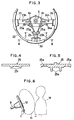
- the illustrated steering wheel ring core 22 is divided into upper member 21A and lower member 22A of half rings respectively.
- the upper member 21A is of an elongated configuration in an up and down direction (L1>L2) as shown in Figure 24.
- the lower member 22A is of an elongated configuration in a left and right direction (L4>L3) as shown in Figure 25.
- the upper member 21A is connected with the lower member 22A at the end portions 21a and 22a through outer portions 23a and 24a as shown in Figure 26.
- the section modulus of the upper member 21A is made greater than that of the lower member 22A without changing the weight in a direction along which the impact force acts.
- the lower member 22A of the wheel ring core 22 is easily deflected and displaced forward staying away from the driver M.
- the wheel ring core 22 absorbs the impact energy as it is deflected.
- the wheel ring core 22 which is not used to support the air bag module 10 is not needed to be stiff to that effect. This enables the wheel ring core 22 to be flexible enough to absorb the impact energy in response to the forward movement of the driver M.
- the steering wheel ring 22 in the former embodiment is divided into two pieces, it is not necessarily divided.
- the steering wheel ring 22 can be constituted by changing flexibility between the lower half portion and upper half portion thereof so that the lower half portion can be made flexible.
- lower member 22B is smaller than upper member 21B in diameter as shown in Figure 27 to make the lower half portion of the steering wheel ring core 22 flexible.
- constricted portions 22e, 22e are formed at the position lower than the outer end portions 23a and 24a of the upper spoke cores 23, 24 as shown in Figure 28.
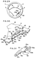
- the illustrated steering wheel assembly 1 is provided with operation switches 133a, 133b in a space defined by the spokes 4 and 5.
- the switches 133a, 133b are mounted on the steering wheel assembly 1 through a bracket 131.
- a base portion 132 which is joined with the switches 133a, 133b is fixed to the bracket 131 through screws 134.
- the bracket 131 is disposed to connect the spoke core 24 with the spoke core 25.
- the bracket 131 is connected with the extension 24a of the spoke 24 at an upper end and with the extension 25a of the spoke 25.
- the base portion 132 is formed with a hole 132a for engaging with a positioning pin 139.
- the switches 133a, 133b can be disposed in a space defined by the spoke core 23 and the spoke core 24 and can be mounted thereon through the extensions 23a and 25a.
- the bracket 131 is formed with a round hole 131a at the upper end portion.
- a screw 135 is inserted into the hole 131a and a hole 24b of the extension 24a so that the upper end of the bracket 131 is joined with the spoke core 24.
- the bracket 131 is formed with a cut out portion 131b at the lower end. After the cut out portion 131b is aligned with a hole 25b, a screw 36 is applied to the cut portion 131b and the hole 25b so that the lower end of the bracket 131 is joined with the spoke 25.
- the bracket 131 Since the lower end of the bracket 131 is an open end, it is easy to be released from the spoke core 25 when an impact force is acted thereon forward.
- the bracket 131 is formed with a folded portion or a flexible portion 131c lower than a point where the base portion 132 is located.
- the flexible portion 131c allows the lower portion of the bracket 131 to make a forward movement smoothly when subjected to a forward force.
- the lower portion of the spoke core 25 can be readily displaced together with the bracket 131 when subjected to a forward force greater than a predetermined value. If the forward force acts on the lower portion of the steering wheel assembly 1 beyond an allowable maximum deflection of the flexible portion 131c of the bracket 131, the lower end of the bracket 131 is released from the spoke core 25 because of the open end. This assures that the lower portion of the steering wheel assembly 1 makes a smooth forward movement in response to the forward force by the driver.
- bracket 151 for switches 153a, 153b there is shown another structure of bracket 151 for switches 153a, 153b.
- the illustrated bracket 151 is formed with round holes 151a and 151b at both ends.
- a flexible portion 151c is formed with a plurality of folded portions lower than a base portion 152 unlike a single folded portion of the bracket 131 of the former embodiment to enhance the flexibility.
- the spoke core 25 is displaced forward by virtue of the groove portion 30 and the bracket 151 is displaced forward following the spoke core 25 without disengaging from the spoke core 25.
- the brackets 131 and 151 ensure that the lower portion of the steering wheel assembly 1 makes a smooth forward displacement when subjected a forward force by the driver beyond a predetermined value.
- the central spoke 25 is formed with a notched portion 25n on the back side by partly removing the reinforcement rib 25s so as to reduce the stiffness thereof. As a result, when the lower portion of the steering wheel assembly is subjected to a forward force, the spoke core 25 is deflected forward at the notched portion 25n.
- a cover member 110 is disposed on an upper surface opposite to the surface where the notched portion 25n is formed.
- the cover member 110 covers an area corresponding to the notched portion 25n.
- the cover member 110 is fixed onto the spoke core 25 at an upper end portion by means of the bolt 17b and nut 17n together with the bracket 16 of the air bag module 10 and by means of a screw 112 at a lower end portion.
- cover member 110 there is shown another structure of cover member 110.
- the cover member 110 straddles both sides of the notched portion 25n on the opposite surface thereto as well as the former embodiment.
- the illustrated cover member 110 is fixed to the spoke core 25 by means of screws 111 and 112 independent from the air bag module 10.
- cover member 110 is provided commonly as bracket 16 of the air bag module 10. Namely, the bracket 16 is extended beyond a position of notched portion 25n and fixed to the spoke core 25 at a lower end portion by screw 112. According to the illustrated structure, the number of parts can be reduced and it can be easily assembled.
- notched portion 25n can be formed as close as possible to the center of the steering wheel ring 2. That is, the notched portion 25n is located upper than the hole 25h for fixing the air bag module 10 through the bracket 16 by the bolt 17b and nut 17n. This structure eliminates the necessity of the cover member without deteriorating the safety of the air bag system.
Landscapes
- Engineering & Computer Science (AREA)
- Mechanical Engineering (AREA)
- Chemical & Material Sciences (AREA)
- Combustion & Propulsion (AREA)
- Transportation (AREA)
- Air Bags (AREA)
- Steering Controls (AREA)
Claims (22)
- Lenkradvorrichtung, umfassend:
einen Lenkradring (2);
eine Vielzahl von Speichen (3, 4, 5), die den Lenkradring (2) auf der Lenkwelle (9) tragen, wobei eine erste der Speichen (5) in einer neutralen Stellung des Lenkradringes von einer Lenkwelle (9) nach unten ragt;
ein Airbag-Gehäuse (14, 15), das an einem oberen Endabschnitt der Lenkwelle (9) angeordnet ist;
einen Airbag (11), der in dem Airbag-Gehäuse im zusammengelegten Zustand aufgenommen ist;
einen Gasgenerator (12), um den Airbag mit Gas aufzublasen; und
einen Zünder (13), um ein Material in dem Gasgenerator zu entzünden, um das Gas zu erzeugen;
eine Verschiebeeinrichtung auf der ersten Speiche (5) oder einem unteren Abschnitt des Lenkradrings (2), mit der die erste Speiche (5) und der untere Abschnitt des Lenkradrings (2) verschoben werden kann, wenn auf die erste Speiche (5) und den unteren Abschnitt des Lenkradrings (2) eine nach vorn gerichtete Kraft wirkt, die größer ist als ein vorbestimmter Wert;
dadurch gekennzeichnet, daß die Verschiebeeinrichtung die Verschiebung der ersten Speiche (5) und des unteren Abschnitts des Lenkradrings (2) ermöglicht, ohne die Winkelposition der Ebene, in der sich das Airbag-Gehäuse (14, 15) befindet, in bezug auf die Lenkwelle (9) zu ändern. - Vorrichtung nach Anspruch 1, bei der die Anzahl der Speichen (3, 4, 5) drei ist, umfassend die erste Speiche (5) sowie die zweite und die dritte Speiche (3, 4).
- Vorrichtung nach Anspruch 1, bei der die erste Speiche mit einem Gelenkabschnitt ausgebildet ist, an dem das Airbag-Gehäuse angeschlossen wird, und mit einem flexiblen Abschnitt, der radial außerhalb von dem Gelenkabschnitt angeordnet ist.
- Lenkradvorrichtung nach Anspruch 2, bei der die erste, die zweite und die dritte Speiche mit dem Airbag-Gehäuse verbunden ist, wobei die Festigkeit der Verbindung zwischen der ersten Speiche und dem Airbag geringer ist als die zwischen der zweiten und dritten Speiche und dem Airbag.
- Lenkradvorrichtung nach Anspruch 1, bei der ein unterer Abschnitt der ersten Speiche von dem Airbag-Gehäuse gelöst wird, wenn eine nach vorn gerichtete Kraft, die größer ist als ein vorbestimmter Wert, auf den unteren Abschnitt der Lenkradvorrichtung einwirkt.
- Lenkradvorrichtung nach Anspruch 1, bei der die erste Speiche mit einem unteren Endabschnitt des Airbag-Gehäuses durch einen Reibeingriff verbunden ist, der gelöst wird, wenn eine nach vorn gerichtete Kraft, die größer ist als ein vorbestimmter Wert, auf den unteren Abschnitt der Lenkradvorrichtung einwirkt.
- Lenkradvorrichtung nach Anspruch 6, bei der eine Eingriffskraft des Reibeingriffs durch einen Bolzen gesteuert wird, der sich senkrecht zu einer Richtung erstreckt, in der die erste Speiche verschoben wird, wenn auf den unteren Abschnitt der Lenkradvorrichtung eine nach vorn gerichtete Kraft wirkt.
- Lenkradvorrichtung nach Anspruch 1, bei der die erste Speiche mit einem unteren Abschnitt des Airbag-Gehäuses durch einen Verbindungsstift verbunden ist, der zerbricht, um die erste Speiche von dem Airbag-Gehäuse zu lösen, wenn auf einen unteren Abschnitt der Lenkradvorrichtung eine nach vorn gerichtete Kraft wirkt, die größer ist als ein vorbestimmter Wert.
- Lenkradvorrichtung nach Anspruch 1, bei der die erste Speiche mit einem unteren Abschnitt des Airbag-Gehäuses durch einen Kunststoffbolzen verbunden ist, der es ermöglicht, daß die erste Speiche nach vorn verschoben wird, wenn auf einen unteren Abschnitt der Lenkradvorrichtung eine nach vorn gerichtete Kraft wirkt, die größer ist als ein vorbestimmter Wert.
- Lenkradvorrichtung nach Anspruch 1, bei der die erste Speiche mit einem unteren Abschnitt des Airbag-Gehäuses durch eine Kunststofftülle verbunden ist, die es ermöglicht, daß die erste Speiche von einem unteren Abschnitt des Airbag-Gehäuses gelöst wird, wenn auf einen unteren Abschnitt der Lenkradvorrichtung eine nach vorn gerichtete Kraft wirkt, die größer ist als ein vorbestimmter Wert.
- Lenkradvorrichtung nach Anspruch 1, bei der die erste Speiche mit einen unteren Abschnitt des Airbag-Gehäuses durch einen flexiblen, stark zusammengedrückten Faltenbalg verbunden ist, der es ermöglicht, daß die erste Speiche in Richtung nach vorne von dem Airbag-Gehäuse weggeschoben wird, wenn auf die Lenkradvorrichtung eine nach vorn gerichtete Kraft wirkt, die größer ist als ein vorbestimmter Wert.
- Lenkradvorrichtung nach Anspruch 1, bei der der Lenkradring eine untere Hälfte relativ geringer Steifigkeit und eine obere Hälfte relativ hoher Steifigkeit besitzt, so daß die untere Hälfte des Lenkradrings nach vorn geschoben wird, wenn auf einen unteren Abschnitt der Lenkradvorrichtung eine nach vorn gerichtete Kraft wirkt, die größer ist als ein vorbestimmter Wert.
- Lenkradvorrichtung nach Anspruch 12, bei der die untere Hälfte des Lenkradrings im Schnitt in Richtung nach oben und unten langgestreckt kreisförmig ausgebildet ist, und die obere Hälfte im Schnitt in Richtung nach vorn und nach hinten langgestreckt kreisförmig ausgebildet ist.
- Lenkradvorrichtung nach Anspruch 12, bei der die untere Hälfte des Lenkradrings im Durchmesser kleiner ist als die obere Hälfte.
- Lenkradvorrichtung nach Anspruch 12, bei der die untere Hälfte des Lenkradrings mit einem verengten Abschnitt ausgebildet ist, der nach oben und nach unten verengt ist, um die Flexibilität zu verbessern.
- Lenkradvorrichtung nach Anspruch 2, des weiteren umfassend ein Verbindungselement zur Verbindung der ersten Speiche mit einer von der zweiten und der dritten Speiche, wobei das Verbindungselement mit einem flexiblen Abschnitt ausgebildet ist, der es ermöglicht, daß ein unterer Abschnitt der Lenkradvorrichtung nach vorn geschoben wird, wenn auf den unteren Abschnitt der Lenkradvorrichtung eine nach vorn gerichtete Kraft wirkt, die größer ist als ein vorbestimmter Wert.
- Lenkradvorrichtung nach Anspruch 16, bei der das Verbindungselement mit einem Trennmechanismus versehen ist, der das Verbindungselement von der ersten Speiche löst, damit ein unterer Abschnitt der Lenkradvorrichtung nach vorn geschoben werden kann, wenn auf den unteren Abschnitt des Lenkrades eine nach vorn gerichtete Kraft wirkt, die größer ist als ein vorbestimmter Wert.
- Lenkradvorrichtung nach Anspruch 2, bei der die Verschiebeeinrichtung auf der ersten Speiche ausgebildet ist, die mit einem Abschnitt von geringerer Steifigkeit versehen ist, der weggebogen wird, so daß ein unterer Abschnitt der Lenkradvorrichtung nach vorn geschoben werden kann, wenn auf den unteren Abschnitt der Lenkradvorrichtung eine nach vorn gerichtete Kraft wirkt, die größer ist als ein vorbestimmter Wert.
- Lenkradvorrichtung nach Anspruch 18, bei der ein Abdeckelement auf der ersten Speiche über dem weniger steifen Abschnitt vorgesehen ist.
- Lenkradvorrichtung nach Anspruch 19, bei der das Abdeckelement gemeinsam mit einer unteren Halterung für das Airbag-Gehäuse ausgebildet ist, durch die das Airbag-Gehäuse mit der ersten Speiche verbunden ist.
- Lenkradvorrichtung nach Anspruch 20, bei der die untere Halterung nach unten ragt, um das Abdeckelement zu bilden.
- Lenkradvorrichtung nach Anspruch 20, bei der der weniger steife Abschnitt auf der ersten Speiche radial einwärts von der Verbindungsstelle zwischen der Halterung (16) und der ersten Speiche ausgebildet ist.
Applications Claiming Priority (10)
| Application Number | Priority Date | Filing Date | Title |
|---|---|---|---|
| JP2326704A JPH04193649A (ja) | 1990-11-27 | 1990-11-27 | 自動車のステアリングホイール構造 |
| JP326704/90 | 1990-11-27 | ||
| JP32777590 | 1990-11-27 | ||
| JP327775/90 | 1990-11-27 | ||
| JP2337576A JP3061637B2 (ja) | 1990-11-30 | 1990-11-30 | 自動車のステアリングホイール構造 |
| JP337576/90 | 1990-11-30 | ||
| JP40074/91 | 1991-03-06 | ||
| JP3040074A JP3005724B2 (ja) | 1991-03-06 | 1991-03-06 | 自動車のステアリング構造 |
| JP23009191A JP3169240B2 (ja) | 1990-11-27 | 1991-09-10 | 自動車のステアリングホイール構造 |
| JP230091/91 | 1991-09-10 |
Publications (2)
| Publication Number | Publication Date |
|---|---|
| EP0488618A1 EP0488618A1 (de) | 1992-06-03 |
| EP0488618B1 true EP0488618B1 (de) | 1996-05-08 |
Family
ID=27522071
Family Applications (1)
| Application Number | Title | Priority Date | Filing Date |
|---|---|---|---|
| EP91310816A Expired - Lifetime EP0488618B1 (de) | 1990-11-27 | 1991-11-25 | Lenkradstruktur für Kraftfahrzeug |
Country Status (3)
| Country | Link |
|---|---|
| US (1) | US5310218A (de) |
| EP (1) | EP0488618B1 (de) |
| DE (1) | DE69119370T2 (de) |
Families Citing this family (25)
| Publication number | Priority date | Publication date | Assignee | Title |
|---|---|---|---|---|
| DE69219996T2 (de) * | 1991-10-28 | 1998-01-08 | Toyoda Gosei Kk | Lenkrad mit einbegriffener Luftsackeinheit |
| JPH0592004U (ja) * | 1992-03-12 | 1993-12-14 | センサー・テクノロジー株式会社 | エアバッグモジュール |
| US5501485A (en) * | 1992-12-02 | 1996-03-26 | Larry J. Winget | Snap-on air bag cover |
| GB2282352A (en) * | 1993-10-02 | 1995-04-05 | Ford Motor Co | Mounting air bags in vehicle steering wheels. |
| US5375876A (en) * | 1993-10-05 | 1994-12-27 | Tip Engineering Group, Inc. | Air bag deployment door installation |
| FR2711108B1 (fr) * | 1993-10-15 | 1998-06-12 | Gersteen | Volant de direction pour véhicules automobiles, et pièce de montage et colonne de direction adaptées à coopérer avec ce volant. |
| AU7941794A (en) * | 1993-10-15 | 1995-05-04 | Gersteen | Steering wheel for motor vehicles, mounting component and steering column cooperating with said steering wheel, and method of manufacture |
| FR2716857B1 (fr) * | 1994-03-03 | 1997-07-18 | Autoliv Dev | Volant avec dispositif de protection anti-choc à sac gonflable prémonté. |
| IT236740Y1 (it) * | 1995-03-16 | 2000-08-17 | Momo Spa | Volante per autoveicolo provvisto di dispositivo di protezionea cuscino d'aria |
| DE19510418A1 (de) * | 1995-03-24 | 1996-09-26 | Mst Automotive Gmbh | Sicherheitslenkrad |
| US5720494A (en) * | 1995-12-27 | 1998-02-24 | Toyoda Gosei Co., Ltd. | Steering wheel with air bag device |
| US5706707A (en) * | 1996-07-02 | 1998-01-13 | Breed Automotive Technology, Inc. | Steering wheel armature with stabilizers |
| DE29616891U1 (de) * | 1996-09-27 | 1997-01-30 | Trw Occupant Restraint Systems Gmbh, 73551 Alfdorf | Einrichtung zum Befestigen eines Gassackmoduls |
| US5947630A (en) * | 1996-11-08 | 1999-09-07 | Breed Automotive Technology, Inc. | Side air bag module attachment |
| DE69809337T2 (de) * | 1997-06-24 | 2003-08-28 | Toyoda Gosei Co., Ltd. | Lenkrad mit einem Luftsackmodul |
| DE29802472U1 (de) * | 1998-02-13 | 1998-04-23 | TRW Automotive Safety Systems GmbH, 63743 Aschaffenburg | Lenkrad mit eingestecktem Airbagmodul |
| US5979860A (en) * | 1998-04-16 | 1999-11-09 | Chrysler Corporation | Steering column support apparatus with shearable ribs |
| JP3786807B2 (ja) * | 1999-12-14 | 2006-06-14 | 日本プラスト株式会社 | 車両用ステアリングホイール |
| SE517015C2 (sv) * | 2000-07-14 | 2002-04-02 | Volvo Personvagnar Ab | Monteringsmodul avsedd för en ratt i ett fordon samt förfarande för dess montering |
| JP3431012B2 (ja) | 2000-10-10 | 2003-07-28 | 豊田合成株式会社 | ステアリングホイール |
| DE102004022635B4 (de) * | 2004-05-07 | 2006-03-30 | Dr.Ing.H.C. F. Porsche Ag | Lenkrad für ein Kraftfahrzeug |
| JP2007062470A (ja) * | 2005-08-30 | 2007-03-15 | Toyoda Gosei Co Ltd | 操舵装置 |
| GB2508954B (en) * | 2012-09-26 | 2015-08-26 | Nihon Plast Co Ltd | Yieldable attachment of module to steering handle |
| JP6538297B2 (ja) * | 2013-06-17 | 2019-07-03 | 日本プラスト株式会社 | ステアリングホイール |
| DE102020115134A1 (de) | 2020-06-08 | 2021-12-09 | ABUS August Bremicker Söhne Kommanditgesellschaft | Schlüsselrohling und Schlüssel zum Betätigen eines Scheibenzylinders sowie Verfahren zum Herstellen eines solchen Schlüsselrohlings und Schlüssels |
Family Cites Families (11)
| Publication number | Priority date | Publication date | Assignee | Title |
|---|---|---|---|---|
| GB1251189A (de) * | 1968-01-17 | 1971-10-27 | ||
| DE1945480A1 (de) * | 1969-09-09 | 1971-04-08 | Petri Lenkradwerk | Mehrspeichensicherheitslenkrad |
| US3773352A (en) * | 1972-03-30 | 1973-11-20 | D Radke | Multiple ignition system for air cushion gas supply |
| JPS5145367B2 (de) * | 1972-04-19 | 1976-12-03 | ||
| FR2353425A1 (fr) * | 1976-06-02 | 1977-12-30 | Quillery | Perfectionnements aux volants de direction |
| US4945786A (en) * | 1986-02-14 | 1990-08-07 | Toyoda Gosei Co., Ltd. | Steering wheel |
| CA1286952C (en) * | 1986-02-28 | 1991-07-30 | Kiyoshi Honda | Steering wheel assembly with air bag |
| JPS638069A (ja) * | 1986-06-27 | 1988-01-13 | Toyoda Gosei Co Ltd | ステアリングホイ−ル |
| FR2627448B1 (fr) * | 1988-02-19 | 1992-10-23 | Ecia Equip Composants Ind Auto | Volant de direction notamment pour vehicule automobile |
| SE463303B (sv) * | 1989-02-14 | 1990-11-05 | Volvo Ab | Fordonsratt med gaskudde |
| JPH03169764A (ja) * | 1989-11-30 | 1991-07-23 | Toyoda Gosei Co Ltd | パツドを備えたステアリングホイール |
-
1991
- 1991-11-22 US US07/796,335 patent/US5310218A/en not_active Expired - Lifetime
- 1991-11-25 DE DE69119370T patent/DE69119370T2/de not_active Expired - Fee Related
- 1991-11-25 EP EP91310816A patent/EP0488618B1/de not_active Expired - Lifetime
Also Published As
| Publication number | Publication date |
|---|---|
| EP0488618A1 (de) | 1992-06-03 |
| US5310218A (en) | 1994-05-10 |
| DE69119370T2 (de) | 1996-11-28 |
| DE69119370D1 (de) | 1996-06-13 |
Similar Documents
| Publication | Publication Date | Title |
|---|---|---|
| EP0488618B1 (de) | Lenkradstruktur für Kraftfahrzeug | |
| EP1511647B1 (de) | Verschiebbare kühlerhaubenanordnung | |
| AU2007315615B2 (en) | Knee air bag with column | |
| US5829777A (en) | Air bag device | |
| US20080238071A1 (en) | Steering column of vehicle having collision energy absorbing apparatus | |
| US6345842B1 (en) | Shock absorbing type steering apparatus and a structure for mounting to an automobile body the steering apparatus | |
| JPH07501297A (ja) | 車両用ステアリングコラムを介して伝達されるエネルギーの吸収装置 | |
| EP1518775B1 (de) | Stossabsorbierende lenksäulenvorrichtung für fahrzeug | |
| US6435555B1 (en) | Collapsible steering column and method | |
| US7261317B2 (en) | Airbag system | |
| CA1286952C (en) | Steering wheel assembly with air bag | |
| JPS62234781A (ja) | エアバツグ装備式ステアリングホイ−ル | |
| US20050035574A1 (en) | Assembly structure of airbag case | |
| JP2005096731A (ja) | 衝撃吸収式ステアリングコラム装置 | |
| JPH09169279A (ja) | 自動車用ステアリングコラム | |
| US7077434B2 (en) | Impact absorption structure of a steering column cover for a vehicle | |
| US6126193A (en) | Steering wheel | |
| JPH07285445A (ja) | チルト式ステアリング装置 | |
| JP3169240B2 (ja) | 自動車のステアリングホイール構造 | |
| US6003406A (en) | Steering wheel having a collapsible hub | |
| JP2511850Y2 (ja) | ステアリングホイ―ル | |
| JP3100290B2 (ja) | ステアリングコラムの支持構造 | |
| JP2008265573A (ja) | 車両用衝撃吸収式ステアリングコラム装置 | |
| KR19990019892A (ko) | 차량용 스티어링 칼럼의 충격흡수구조 | |
| JP2897061B2 (ja) | 車両用ステアリングホイール |
Legal Events
| Date | Code | Title | Description |
|---|---|---|---|
| PUAI | Public reference made under article 153(3) epc to a published international application that has entered the european phase |
Free format text: ORIGINAL CODE: 0009012 |
|
| AK | Designated contracting states |
Kind code of ref document: A1 Designated state(s): DE FR GB |
|
| 17P | Request for examination filed |
Effective date: 19921102 |
|
| 17Q | First examination report despatched |
Effective date: 19940201 |
|
| GRAH | Despatch of communication of intention to grant a patent |
Free format text: ORIGINAL CODE: EPIDOS IGRA |
|
| GRAA | (expected) grant |
Free format text: ORIGINAL CODE: 0009210 |
|
| AK | Designated contracting states |
Kind code of ref document: B1 Designated state(s): DE FR GB |
|
| REF | Corresponds to: |
Ref document number: 69119370 Country of ref document: DE Date of ref document: 19960613 |
|
| ET | Fr: translation filed | ||
| PLBE | No opposition filed within time limit |
Free format text: ORIGINAL CODE: 0009261 |
|
| STAA | Information on the status of an ep patent application or granted ep patent |
Free format text: STATUS: NO OPPOSITION FILED WITHIN TIME LIMIT |
|
| 26N | No opposition filed | ||
| PGFP | Annual fee paid to national office [announced via postgrant information from national office to epo] |
Ref country code: FR Payment date: 20001110 Year of fee payment: 10 |
|
| PGFP | Annual fee paid to national office [announced via postgrant information from national office to epo] |
Ref country code: GB Payment date: 20001122 Year of fee payment: 10 |
|
| PG25 | Lapsed in a contracting state [announced via postgrant information from national office to epo] |
Ref country code: GB Free format text: LAPSE BECAUSE OF NON-PAYMENT OF DUE FEES Effective date: 20011125 |
|
| REG | Reference to a national code |
Ref country code: GB Ref legal event code: IF02 |
|
| GBPC | Gb: european patent ceased through non-payment of renewal fee |
Effective date: 20011125 |
|
| PG25 | Lapsed in a contracting state [announced via postgrant information from national office to epo] |
Ref country code: FR Free format text: LAPSE BECAUSE OF NON-PAYMENT OF DUE FEES Effective date: 20020730 |
|
| REG | Reference to a national code |
Ref country code: FR Ref legal event code: ST |
|
| REG | Reference to a national code |
Ref country code: FR Ref legal event code: ST |
|
| PGFP | Annual fee paid to national office [announced via postgrant information from national office to epo] |
Ref country code: DE Payment date: 20061123 Year of fee payment: 16 |
|
| PG25 | Lapsed in a contracting state [announced via postgrant information from national office to epo] |
Ref country code: DE Free format text: LAPSE BECAUSE OF NON-PAYMENT OF DUE FEES Effective date: 20080603 |