EP0488655A2 - Procédé de transformation de couleurs - Google Patents
Procédé de transformation de couleurs Download PDFInfo
- Publication number
- EP0488655A2 EP0488655A2 EP91310892A EP91310892A EP0488655A2 EP 0488655 A2 EP0488655 A2 EP 0488655A2 EP 91310892 A EP91310892 A EP 91310892A EP 91310892 A EP91310892 A EP 91310892A EP 0488655 A2 EP0488655 A2 EP 0488655A2
- Authority
- EP
- European Patent Office
- Prior art keywords
- chroma
- color
- image data
- lightness
- gamut
- Prior art date
- Legal status (The legal status is an assumption and is not a legal conclusion. Google has not performed a legal analysis and makes no representation as to the accuracy of the status listed.)
- Withdrawn
Links
Images





Classifications
-
- H—ELECTRICITY
- H04—ELECTRIC COMMUNICATION TECHNIQUE
- H04N—PICTORIAL COMMUNICATION, e.g. TELEVISION
- H04N1/00—Scanning, transmission or reproduction of documents or the like, e.g. facsimile transmission; Details thereof
- H04N1/46—Colour picture communication systems
- H04N1/56—Processing of colour picture signals
- H04N1/60—Colour correction or control
-
- G—PHYSICS
- G06—COMPUTING OR CALCULATING; COUNTING
- G06T—IMAGE DATA PROCESSING OR GENERATION, IN GENERAL
- G06T9/00—Image coding
- G06T9/005—Statistical coding, e.g. Huffman, run length coding
-
- H—ELECTRICITY
- H04—ELECTRIC COMMUNICATION TECHNIQUE
- H04N—PICTORIAL COMMUNICATION, e.g. TELEVISION
- H04N1/00—Scanning, transmission or reproduction of documents or the like, e.g. facsimile transmission; Details thereof
- H04N1/46—Colour picture communication systems
- H04N1/56—Processing of colour picture signals
- H04N1/60—Colour correction or control
- H04N1/6058—Reduction of colour to a range of reproducible colours, e.g. to ink- reproducible colour gamut
Definitions
- the present invention relates to a color estimation method which is suited to a colour component image correction device which is used to produce, for example, a colour hard copy from an image on a colour CRT.
- colorimetric systems are different from each other.
- a color CRT is formed through an additive color mixing in which a phosphor RGB colorimetric system is used as the color representation system.
- a color hard copy is formed through a subtractive color mixing in which, for example, a YMC coordinate system, is used as the colorimetric system. In this case, the image data is converted or the colors are corrected between these colorimetric systems.
- red (R), green (G), and blue (B) image data are supplied to a color masking device 10 as shown in Fig. 21, yellow (Y), magenta (M), and cyan (C) image data (color correction data) are outputted from the color masking device 10, and the color correction data is supplied to a color printer 100.
- Color patches of combinations of R, G, and B image data of color CRT are displayed on the display device and measured colorimetrically so as to obtain the values of the colorimetric system.
- color patches of combinations of Y, M, and C image data of a color hard copy are output and measured colorimetrically so as to obtain the values of the same colorimetric system as that of color CRT.
- a combination of Y, M, and C image data of a color hard copy is obtained by an interpolation operation so as to obtain the same as or close to the value of the colorimetric system obtained by measuring the color patches of combinations of R, G, and B image data of the color CRT on the display.
- the color reproduction range or gamut in R,G, and B image data of color CRT is generally wider than the color reproduction range or gamut in Y, M, and C image data of a colour hard copy.
- a solid line “a” indicates the color reproduction gamut of color CRT and a solid line “b” indicates the color reproduction gamut of a hard copy.
- the aim of the present invention is to provide a method, for example for reproducing a color CRT as a color hard copy so that the balance of chroma values between the entire colors is not changed and the lightness and chroma are kept satisfactory.
- a colour estimation method in which, the values of the colourimetric system for each combination of a plurality of input color component image information is obtained and the values of the colorimetric system for each combination of a plurality of output color component image information is obtained.
- a CIE standard L*u*v* or L*a*b* colorimetric system is used as a colorimetric system.
- L* among the values of the colorimetric system obtained for an optional combination of the input color component image information is converted according to the ratio of the difference between the maximum and minimum values of the lightness of the input side color gamut on the lightness axis which comprise the value of the colorimetric system obtained for each combination of the input color component image information to the difference between the maximum and minimum values of the lightness of the output side color gamut on the lightness axis which comprise the value of the colorimetric system obtained for each combination of the output color component image information.
- u* and v* or a* and b* among the values of the colorimetric system obtained for an optional combination of the input color component image information are not corrected when the chroma is smaller than a value which is "a" (a ⁇ 1.0) times of the maximum chroma value at the hue and lightness of the output side color gamut.
- u* and v* or a* and b* are converted so that the hue is fixed and the chroma is converted according to the ratio of the difference between the maximum chroma value at the hue and lightness of the input side color gamut and the value which is "a" times of the maximum chroma value at the hue and lightness of the output side color gamut to the difference between the maximum chroma value at the hue and lightness of the output side color solid and a value which is "a" times of that maximum chroma value.
- u* and v* or a* and b* among the values of the colorimetric system obtained for an optional combination of the input color component image information are not corrected when the chroma is smaller than a value which is "a" (a ⁇ 1.0) times of the maximum chroma value of the output side color gamut on a straight line passing the lightness and the chroma at the hue.
- L* is converted according to the conversion amount of chroma.
- the L* value is converted according to the conversion amount of chroma so as to decrease the lightness as the chroma decreases.
- L* among the values of the colorimetric system obtained for each combination of the input color component image information is converted according to the ratio of the lightness range of the input side color gamut on the lightness axis to that of the output side color gamut, and the lightness of the input side color gamut is compressed and mapped.
- u* and v* or a* and b* among the values of the colorimetric system obtained for each combination of the input color component image information are converted according to the difference of the chroma range between the two color gamuts and the chroma of the input side color gamut is compressed and mapped.
- the color reproduction scope on the input side is included in the color reproduction gamut on the output side by a natural conversion result, and the color reproduction obtained by the output color component image information becomes natural.
- the chroma in a high lightness area is compressed so that the lightness decreases as the chroma decreases, and when u* and v* or a* and b* are converted and the chroma is compressed and mapped, the decrease amount of chroma is suppressed.
- u* and v* or a* and b* among the values of the colorimetric system obtained for an optional combination of the input color component image information are not corrected when the chroma is smaller than a value which is "a" (a ⁇ 1.0) times of the maximum chroma value at the hue and lightness of the output side color gamut.
- u* and v* or a* and b* are converted so that to the area enclosed with the inner color gamut surface which comprises the value which is "a" times of the maximum chroma value at each hue and lightness in the output side color gamut and the inner surface of the output side color gamut which comprises the maximum chroma value at each hue and lightness in the output side color gamut, the entire area enclosed with the above metnioned inner surface of the output side color gamut and the inner surface of the input side color gamut which comprises the maximum chroma value at each hue and lightness in the input side color gamut corresponds continuously.
- the hue is moved toward the maximum chroma point of the corresponding color of the output side color gamut as the chroma decreases.
- a fourth aspect of the invention as another correspondence method for the third aspect, in case that three primary colors of input color component information differ from that of output color when the hue, which is obtained by an optional combination of the input color component image information, is within a predetermined area of one of the maximum chroma points of the three primary colors of the input side color gamut, the hue is moved toward one of two hues, which are short distance from the above mentioned hue, at the maximum chroma points of the three primary colors of the output side color gamut.
- the hue is moved so that the peak of each color of the input side color gamut moves toward the peak of the corresponding color of the output side color gamut.
- the color reproduction gamut on the input side is included in the color reproduction scope on the output side by natural conversion with the entire chroma balance side is included in the color reproduction gamut on the output side by natural conversion with the entire chroma balance kept, the color reproduction obtained by the output color component image information provides satisfactory lightness and chroma, and the chroma is well balanced as a whole.
- the hue is moved so that the peaks of the three primary colors of the input side color gamut is moved to the peaks of the three primary colours of the output side colour gamut.
- the 729 colors may be measured colorimetrically, though the measurement count is so large.
- the values of the XYZ colorimetric system may be calculated by using the basic expression indicated below, which is well known as a color CRT color reproduction expression.
- the coefficients XR, XG, XB, YR, YG, YB, ZR, ZG, ZB, and gamma are determined according to the characteristics of the CRT device used. 10 to 20 points are taken from the quantization levels 0 to 255 for each monochrome of R, G, and B, the colors, which are displayed on the color CRT device using the values, are measured colorimetrically by the spectral radiometer so as to obtain the X, Y, and Z values, and each coefficient is obtained from the relation between the R, G, and B values and the X, Y, and Z values.
- Xn, Yn, and Zn satisfy the following expressions.
- the L*u*v* colorimetric system values are defined as follows: L* TV1 (R, G, B) u* TV1 (R, G, B) v* TV1 (R, G, B)
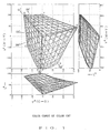
- Fig. 1 shows these values on the L*u*v* colorimetric system. Hereinafter, these values are called the CRT color gamut.
- K image data is obtained from the following relation equation for each combination of Y, M, and C image data, and black K in the amount is added to the color patches of the Y, M, and C image data.
- the color patches are measured by a spectrophotometer, the values of the XYZ colorimetric system are determined, and the values of the L*u*v* colorimetric system are calculated.
- the 729 colors may be printed and measured colorimetrically, though the measurement count is so large.
- the values of the L*u*v* colorimetric system are defined as: L* IN (Y, M, C) u* IN (Y, M, C) v* IN (Y, M, C)
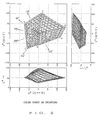
- Fig. 2 shows these values on the L*u*v* colorimetric system. Hereinafter, these values are called the printed matter color gamut.
- each value of the color CRT color gamut values L* TV1, u* TV1, and v* TV1 are converted to L* TV2, u* TV2, and v* TV2.
- L* is converted linearly by the following expression so that the maximum and minimum values of L* of the color CRT color gamut are equal to the maximum and minimum values of L* of the printed matter color gamut.
- u* and v* are converted by the following expressions in the same way.
- u* TV2 L* TV2 L* TV1
- u* TV1 u* TV1
- v* TV2 L* TV2 L* TV1 v* TV1
- a gray wedge target wherein u* and v* are 0 and L* ranges from 20 to 100 at intervals of five quantization levels is provided (see Fig. 3).
- the color gamut value at each step of the gray wedge target is given in the printed matter color gamut (shown in Fig. 2) as a target value T′.
- Fig. 4 shows the Y-M coordinate system.
- Fig. 5 is obtained.
- the apexes B, C, G, and F of the square shown in Fig. 4 correspond to B′, C′, G′, and F′ shown in Fig. 5.
- a value of the color gamut on the L*u*v* colorimetric system, obtained by target patches of the combinations of Y and M is given as a target value T′ (see Fig. 5).
- the target value T′ is in the area enclosed by the lattice points a′, b′, c′, and d′ as shown in Fig. 5, it is inferred that the combination (target value T) of Y and M on the Y-M coordinate system is in the area enclosed by the lattice points a, b, c, and d as shown in Fig. 4.
- the location of the target value T in the area formed by the lattice points a, b, c, and d is obtained by the convergence operation by mapping the colorimetric system shown in Fig. 5 onto the coordinate system shown in Fig. 4.
- the reason for performing the convergence operation is that the conversion from the coordinate system shown in Fig. 4 to the colorimetric system shown in Fig. 5 is well known, though the reverse conversion is complicated and a satisfactory conversion expression is not known.
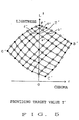
- the area where the target value T' is located is obtained among a plurality of areas formed by 81 lattice points (see Fig. 5).
- the target value T′ is in the area S0′ as shown in Fig. 7, it is inferred that the target value T is in the area S0 which corresponds to the area S0′ as shown in Fig. 6.
- the inferred area S0 is equally divided into 4 areas S1, S2, S3, and S4.
- Five division points, e to i, are calculated by weight average using the peripheral lattice points which are already obtained.
- the values corresponding to the division points, e to i, are converted to those on the L*u*v* colorimetric system, the converted values are plotted on the colorimetric system shown in Fig. 7, and the area among the four areas S1′, S2′, S3′, and S4′ formed by the plotted division points, e′ to i′, where the target value T′ exists, is obtained.
- the target value T′ is in the area S2′ as shown in Fig. 7, it is inferred that the target value T is in the area S2 corresponding to the area S2′ as shown in Fig. 6.
- the inferred area S2 is equally divided into 4 areas S5, S6, S7, and S8.
- Five division points, j to n are calculated by weight average using the peripheral lattice points, which are already obtained, and the division points.
- the values corresponding to the division points, j to n are converted to those on the L*u*v* colorimetric system, the converted values are plotted on the colorimetric system shown in Fig. 7, and the area among the four areas S5′, S6′, S7′, and S8′ formed by the plotted division points, j′ to n′, where the target value T′ exists, is obtained.
- the target value T′ is in the area S8′ as shown in Fig. 7, it is inferred that the target value T is in the area S8 corresponding to the area S8′ as shown in Fig. 6.
- the inferred area S8 is equally divided into 4 areas S9, S10, S11, and S12.
- Five division points, o to s, are calculated by weight average using the peripheral lattice points, which are already obtained, and the division points.
- the values corresponding to the division points, o to s, are converted to those on the L*u*v* colorimetric system, converted values are plotted on the colorimetric system shown in Fig. 7, and the area among the four areas S9′, S10′, S11′, and S12′ formed by the plotted division points o′ to s′, where the target value T′ exists, is obtained.
- the target value T′ is in the area S10′ as shown in Fig. 7, it is inferred that the target value T is in the area S10 corresponding to the area S10′ as shown in Fig. 6.
- the lattice becomes small gradually and is converged finally.
- the target value T can be obtained.
- Images are printed from the image data of Y, M, C, and K at each step, which are obtained as described above, wedge target printing process, and a gray wedge target is produced.
- a gray wedge target wherein u* and v* are 0 and L* ranges from 20 to 100 at intervals of five quantization levels is displayed (see Fig. 3).
- a gray wedge target is displayed on the color CRT device from the image data of R, G, and B at each step, which are obtained as described above.
- the wedge target chart on the color CRT device is compared with the gray wedge target of the printed matter, and whether the condition of discrimination on the boundary at each step of the target on the color CRT device is the same as that of the target of the printed matter is checked.
- the value of the constant r is changed, L* TV3, u* TV3, and v* TV3 are recalculated, the operation in (7) is performed by using L* TV3, u* TV3, and v* TV3 instead of L* TV2, u* TV2, and v* TV2, and the target on the CRT device is compared with the target of the printed matter once again.
- the values are given to the color gamut of the printed matter (shown in Fig. 2) as a target value T′, and the values of Y, M, and C for each combination of R, G, and B are obtained by the convergence operation.
- the target value T′ may be outside the color reproduction gamut of the printed matter.
- the target value T′ is converted to a value within the color reproduction gamut of the printed matter by one of the following methods in Example 1 to Example 5, and then the values of Y, M, and C are obtained by the convergence operation.
- L* TV3, u* TV3, and v* TV3, which are obtained for each combination of R, G, and B, are given to the printed matter color gamut (shown in Fig. 2) as a target value T ⁇ .
- the values of L*, u*, and v* at this time are assumed as L* T ⁇ , u* T ⁇ , and v* T ⁇ .
- the chroma value obtained by u* T ⁇ 2 + v* T ⁇ 2 is rT ⁇ and the hue angle obtained by arctan (v* T ⁇ / u* T ⁇ ) is ⁇ T′
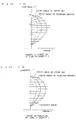
- the chroma value r INmidT ⁇ which is "a" (a ⁇ 1.0) times, for example, about 2/3 times, of the maximum chroma value r INmaxT ⁇ of the color gamut of the printed matter for L* T ⁇ and ⁇ T ⁇ is taken as a threshold value (see Fig. 8).
- r TVmaxT ⁇ is the maximum chroma value of the color gamut on the color CRT device for L* T ⁇ and ⁇ T ⁇ (see Fig. 8).
- L* T′, u* T′, and v* T′ which are converted from L* T ⁇ , u* T ⁇ , and v* T ⁇ are within the color reproduction scope of the printed matter.
- the maximum chroma value is obtained as specified below.
- the target value moves inward on the straight line.
- the meaning of the above straight line is that since the target value moves on the straight line, the rate at which the lightness is decreased or increased so as to decrease the chroma is determined.
- Fig. 10 shows status changes of the straight line which is determined as described above.
- the chroma is converted on the straight line which is determined by the target value T ⁇ like this.
- the chroma value r INmidT ⁇ which is "a" times (a ⁇ 1.0), for example, about 2/3 times of the maximum chroma value r INmaxT ⁇ of the color gamut of the printed matter on the straight line is assumed as a threshold value.
- rT′ (r INmaxT ⁇ - r INmidT ⁇ ) (r TVmaxT ⁇ - r INmidT ⁇ ) ⁇ (rT ⁇ - r INmidT ⁇ ) + r INmidT ⁇
- L* T′, u* T′, and v* T′ which are converted from L* T ⁇ , u* T ⁇ , and v* T ⁇ are within the color reproduction scope of the printed matter.
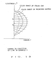
- Example 1 is equivalent to Example 2 wherein L* of the expression of the straight line, Expression 2, is fixed to L* T ⁇ .
- Fig. 12 shows status changes of the straight line in Example 1.
- Fig. 13 shows status changes of the straight line which is determined as described above.
- the chroma r is converted on the straight line which is determined by the target value T ⁇ like this.
- the chroma value r INmidT ⁇ which is "a" times (a ⁇ 1.0), for example, about 2/3 times of the maximum chroma value r INmaxT ⁇ of the color gamut of the printed matter on the straight line is assumed as a threshold value.
- rT′ (r INmaxT ⁇ - r INmidT ⁇ ) (r TVmaxT ⁇ - r INmidT ⁇ ) ⁇ (rT ⁇ - r INmidT ⁇ ) + r INmidT ⁇
- L* T′, u* T′, and v* T′ which are converted from L* T ⁇ , u* T ⁇ , and v* T ⁇ are within the color reproduction scope of the printed matter.
- rT′ is set as shown below depending on ⁇ T ⁇ .
- r TVmaxT ⁇ is the maximum chroma value of the color gamut on the color CRT device for L* TV3 and ⁇ T ⁇ (see Fig. 8).
- 131° is a hue angle at the maximum chroma point of G (green) of the color gamut of color CRT (see Fig. 1)
- 147° is a hue angle at the maximum chroma point of G (green) of the color gamut of the printed matter (see Fig. 2).
- ⁇ T ⁇ 2 (147° - 131°) (r INmaxT ⁇ - r INmidT ⁇ ) (r TVmaxT ⁇ - r INmidT ⁇ ) ⁇ (rT ⁇ - r INmidT ⁇ ) x ( ⁇ T ⁇ - 120°) (131° - 120°) + ⁇ T ⁇
- ⁇ T ⁇ 2 (147° - 131°) (r INmaxT ⁇ - r INmidT ⁇ ) (r TVmaxT ⁇ - r INmidT ⁇ ) ⁇ (rT ⁇ - r INmidT ⁇ ) x (170° - ⁇ T ⁇ ) (170° - ⁇ T ⁇ ) (170° - 131°) + ⁇ T ⁇
- r INmaxT ⁇ 2 indicates the maximum chroma value of the color gamut of the printed matter for L* T ⁇ and ⁇ T ⁇
- r INmidT ⁇ 2 indicates a chroma value which is "a" times of r INmaxT ⁇
- r TVmaxT ⁇ 2 indicates the maximum chroma value of the color gamut of color CRT for L* T ⁇ and ⁇ T ⁇ 2.
- L* T′, u* T′, and v* T′ which are converted from L* T ⁇ , u* T ⁇ , and v* T ⁇ are within the color reproduction gamut of the printed matter.
- the maximum chroma value can be obtained in the same as with Example 1.
- rT′ is set as shown below depending on ⁇ T ⁇ .
- r TVmaxT ⁇ is the maximum chroma value of the color gamut on the color CRT device for L* TV3 and OT ⁇ (see Fig. 8).
- 266° is a hue angle at the maximum chroma point of B (blue) of the color gamut of the color CRT (see Fig. 1)
- 234° is a hue angle at the maximum chroma point of C (cyan) of the color gamut of the printed matter (see Fig. 2).
- ⁇ T ⁇ 2 (234° - 266°) (r INmaxT ⁇ - r INmidT ⁇ ) (r TVmaxT ⁇ - r INmidT ⁇ ) ⁇ (rT ⁇ - r INmidT ⁇ ) x (300° - ⁇ T ⁇ ) (300° - 266°) + ⁇ T ⁇
- ⁇ T ⁇ 2 (234° - 266°) (r INmaxT ⁇ - r INmidT ⁇ ) (r TVmaxT ⁇ - r INmidT ⁇ ) ⁇ (rT ⁇ - r INmidT ⁇ ) x ( ⁇ T ⁇ - 200°) (266° - 200°) + ⁇ T ⁇
- r INmaxT ⁇ 2 indicates the maximum chroma value of the color gamut of the printed matter for L* T ⁇ and ⁇ T ⁇
- r INmidT ⁇ 2 indicates a chroma value which is "a" times of r INmaxT ⁇
- r TVmaxT ⁇ 2 indicates the maximum chroma value of the color gamut of the color CRT for L* T ⁇ and ⁇ T ⁇ 2.
- L* T′, u* T′, and v* T′ which are converted from L* T ⁇ , u* T ⁇ , and v* T ⁇ are within the color reproduction gamut of the printed matter.
- L* among the values of the colorimetric system obtained for each combination of R, G, and B is converted according to the ratio of the lightness range of the color gamut of the color CRT (input side) on the lightness axis to that of the color gamut of the printed matter (output side), and the lightness of the color gamut of the color CRT is compressed and mapped.
- the chroma direction no value is corrected at the overlapped center portion of the color gamut of the color CRT (input) and that of the color gamut of the printed matter (output).
- u* and v* among the values of the colorimetric system obtained for each combination of R, G, and B are converted according to the chroma range of the two color gamuts and the chroma of the color gamut of color CRT is compressed and mapped.
- the color reproduction gamut of color CRT is included in the color reproduction gamut of the printed matter by a natural conversion result, and the color reproduction obtained by a combination of Y, M, C, and K provides satisfactory and natural lightness and chroma.
- the slope of the straight line is positive or negative and the decrease amount of chroma is suppressed when the chroma is compressed and mapped, and hence decreases in color saturation caused by compression and mapping in the high lightness and chroma area or in the low lightness and chroma area can be prevented.
- the hue is moved in the direction from the G (green) peak of the color gamut of the color CRT to the G peak of the color gamut of the printed matter or from the B (blue) peak of the color gamut of the color CRT to the C (cyan) peak of the color gamut of the printed matter, and hence the chroma is balanced as a whole.
- the hue is moved in the direction from the B (blue) peak of the color gamut of the color CRT to the C (cyan) peak of the color gamut of the printed matter.
- the hue may be moved to the M (magenta) peak in the reverse direction.
- the hue range where the hue is moved is limited to one area. A plurality of areas may be used, and Example 4 and Example 5 may be used simultaneously.
- the lightness is kept constant when the chroma is moved.
- the lightness may be changed as the chroma moves.
- the CIE standard L*u*v* colorimetric system is used as a colorimetric system.
- the CIE standard L*a*b* colorimetric system may be used.
- a color masking device which is constructed so that the color correction data (Y, M, C, and K) obtained as described above is stored in a look up table (LUT) beforehand and the color correction data is referred to by input image data (R, G, B), will be described.
- the applicant proposes a method that to reduce the memory capacity, a color space formed by R, G, and B image data is divided into a plurality of basic lattices, Y, M, C, and K image data for a combination of R, G, and B image data positioned at the apexes thereof are stored in the lookup table, and when Y, M, C, and K image data for a combination of R, G, and B image data do not exist, Y, M, C, and K image data are obtained by weight average of the Y, M, C, and K image data at the apexes of the basic lattices containing the R, G, and B image data (interpolation point).
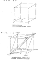
- the volume of each cuboid formed by the apexes which are diagonally positioned to the interpolation point P and point P itself is used as a weighting factor for the Y, M, C, and K image data at the apexes A to H.
- the interpolation point P is connected to the apexes A, B, C, and G, new 4 triangular pyramids are formed, and the volumes V BCGP , V ACGP , V ABGP , and V ABCP can be obtained.
- the Y, M, C, and K image data Yp, Mp, Cp, and Kp at the interpolation point P are calculated from the volumes and the Y, M, C, and K image data Y A to Y G , M A to M G , C A to C G , and K A to K G at the apexes A, B, C, and G using the following expressions:
- V ABCG indicates the volume of the triangular pyramid T.
- the triangular pyramid T to be used is changed.
- the interpolation point P is contained in a triangular pyramid T formed by the apexes A, C, D, and G as shown in Fig. 18 and this triangular pyramid is used.
- the Y, M, C, and K image data Yp, Mp, Cp, and Kp at the interpolation point P can be calculated by 4 times of multiplication accumulation processing.
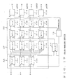
- Fig. 19 shows an actual configuration example of a color masking device.
- numeral 20 indicates a color correction data storage means, and lookup tables (MLUT) 21Y to 21K constituting the storage means 20 store Y, M, C, and K color correction data.
- MLUT lookup tables
- R, G, and B image data are 8 bits long and have 256 gradations.
- 256 is evenly divided into 32 portions by 8 sequentially, for example, starting at 0 as follows: 0, 8, 16, ---, 240, 248
- the Y, M, C, and K image data at the distribution points, that is, at the apexes of the basic lattice whose basic lattice interval is the 8-quantization level are calculated as described above, and the calculated image data are stored in MLUT21Y to MLUT21K.
- Numeral 60 indicates a lookup table (WLUT) constituting a weighting factor storage means.
- WLUT60 stores the weighting factor corresponding to each interpolation point.
- the maximum weighting factor is 255 so that a 8-bit general purpose IC can be used as WLUT60.
- the weighting factors P1 to P8 are as follows:
- the total of weighting factors is always 256.
- the maximum weighting factor is 255 so that a 8-bit general purpose IC can be used as WLUT60.
- the weighting factors V BCGP , V ACGP , V ABGP , and V ABCP are as follows:
- the total of weighting factors is always 256.
- R, G, and B image data are supplied to lookup tables (PLUT) 41R to 41B constituting an address signal generation means 40, and distribution signals are supplied to PLUT41R to PLUT41B from a controller 50.
- PLUT lookup tables
- 5-bit address signals corresponding to the upper 5 bits (indicating the reference points at the apexes of the basic lattice containing the interpolation point P) of R, G, and B image data are outputted from PLUT41R to PLUT41B and supplied to MLUT21Y to MLUT21K.
- 5-bit address signals are outputted sequentially according to distribution signals so that the 8 apexes of the basic lattice containing the interpolation point P are specified sequentially by MLUT21Y to MLUT21K.
- 5-bit address signals are outputted sequentially according to distribution signals so that the 4 apexes of the triangular pyramid containing the interpolation point P are specified sequentially by MLUT21Y to MLUT21K.
- Y, M, C, and K image data outputted from MLUT21Y to MLUT21K are supplied to multipliers (MTL) 31Y to 31K constituting a multiplication accumulation means 30.
- Lower 3 bits (indicating the position of the interpolation point P in the basic lattice) of R, G, and B image data are outputted from PLUT41R to PLUT41B as weighting factor specification signals, and the weighting factor specification signals are supplied to WLUT60.
- Distribution signals are supplied to WLUT60 from the controller 50, and the weighting factors are sequentially outputted according to the distribution signals.
- the 8 weighting factors P1 to P8 are sequentially outputted.
- Weighting factors outputted from WLUT60 are supplied to MTL31Y to MTL31K.
- Y, M, C, and K image data (8 bits long) outputted from MLUT21Y to MLUT21K are multiplied by weighting factors (8 bits long) from WLUT60 in MTL31Y to MTL31K.
- Multiplication outputs of upper 8 bits of MTL31Y to MTL31K are supplied to accumulators (ALU) 32Y to 32K and added by them.
- a reset signal is supplied to ALU32Y to ALU32K from the controller 50.
- the add operation is performed sequentially. Whenever the results are latched by a latch circuit which will be described later, the accumulators are reset.
- the add operation is performed sequentially. Whenever the results are latched by a latch circuit which will be described later, the accumulators are reset.
- the total of 8 weighting factors in the case of the interpolation processing using a cube and the total of 4 weighting factors in the case of the interpolation process using a triangular pyramid are 256.
- the upper 8 bits of multiplication outputs of MTL31y to MTL31K are used, that is, a so-called 8-bit shift is performed.
- the processing of in Expression (3) and 1/V ABCG in Expression (4) is performed.
- Outputs of ALU32Y to ALU32K constituting the multiplication accumulation means 30 are supplied to latch circuits 71Y to 71K.
- a latch pulse is supplied to the latch circuits 71Y to 71k from the controller 50.
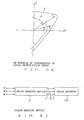
- Fig. 20 shows an example that behind a color masking device (A in the drawing) for outputting Y, M, and C image data without K image data being stored in the lookup table beforehand, a device (B in the drawing), which obtains K image data from Expression (1) and outputs it, is added.
- the memory capacity can be decreased.
- the parts shown in Fig. 20 which correspond to those shown in Fig. 19 are assigned with the same numbers and the detailed description is omitted.
- Y, M, and C image data outputted from the latch circuits 71Y to 71C are supplied to a minimum value detection circuit 81, and the minimum value among Y, M, and C, that is, min[Y, M, C] is detected.
- Detected min[Y, M, C] is supplied to a lookup table 82, and the lookup table 82 outputs K image data which is obtained from the following relational expression.
- L* among the values of the colorimetric system obtained for each combination of the input color component image information is converted according to the ratio of the lightness range of the input side color gamut on the lightness axis to that of the output side color gamut, and the lightness of the input side color gamut is compressed and mapped.
- the chroma direction no value is corrected at the overlapped center portion of the color reproduction gamut of the input side and that of the output side.
- u* and v* or a* and b* among the values of the colorimetric system obtained for each combination of the input color component image information are converted according to the chroma range of the two color gamuts and the chroma of the input side color gamut is compressed and mapped.
- the color reproduction gamut of the input side is included in the color reproduction gamut of the output side by a natural conversion result, and the color reproduction obtained by the output color component image information becomes natural.
- the hue is moved so that the peak of each color of the input side color gamut moves toward the peak of the corresponding color of the output side color gamut. Therefore, the color reproduction gamut on the input side is included in the color reproduction gamut on the output side by natural conversion with the entire chroma balance kept, the color reproduction obtained by the output color component image information provides satisfactory lightness and chroma, and the chroma is well balanced as a whole.
Landscapes
- Engineering & Computer Science (AREA)
- Multimedia (AREA)
- Signal Processing (AREA)
- Physics & Mathematics (AREA)
- General Physics & Mathematics (AREA)
- Theoretical Computer Science (AREA)
- Facsimile Image Signal Circuits (AREA)
- Color Image Communication Systems (AREA)
Applications Claiming Priority (4)
| Application Number | Priority Date | Filing Date | Title |
|---|---|---|---|
| JP321686/90 | 1990-11-26 | ||
| JP321685/90 | 1990-11-26 | ||
| JP2321686A JPH04196676A (ja) | 1990-11-26 | 1990-11-26 | 色推定方法 |
| JP2321685A JPH04196675A (ja) | 1990-11-26 | 1990-11-26 | 色推定方法 |
Publications (1)
| Publication Number | Publication Date |
|---|---|
| EP0488655A2 true EP0488655A2 (fr) | 1992-06-03 |
Family
ID=26570560
Family Applications (1)
| Application Number | Title | Priority Date | Filing Date |
|---|---|---|---|
| EP91310892A Withdrawn EP0488655A2 (fr) | 1990-11-26 | 1991-11-26 | Procédé de transformation de couleurs |
Country Status (2)
| Country | Link |
|---|---|
| US (1) | US5363218A (fr) |
| EP (1) | EP0488655A2 (fr) |
Cited By (12)
| Publication number | Priority date | Publication date | Assignee | Title |
|---|---|---|---|---|
| DE4309878A1 (de) * | 1992-04-06 | 1993-11-04 | Hell Ag Linotype | Verfahren und einrichtung zur analyse und korrektur der bildgradation in bildvorlagen |
| EP0579224A1 (fr) * | 1992-07-15 | 1994-01-19 | Fuji Xerox Co., Ltd. | Procédé et dispositif de traitement d'informations de couleur pour la compression de la gamme et avec l'adaptation de couleur |
| EP0592146A3 (en) * | 1992-10-05 | 1994-07-20 | Canon Information Syst Inc | Color reproduction method and apparatus |
| US5438649A (en) * | 1992-10-05 | 1995-08-01 | Canon Information Systems, Inc. | Color printing method and apparatus which compensates for Abney effect |
| EP0684728A1 (fr) * | 1994-05-26 | 1995-11-29 | Agfa-Gevaert N.V. | Adaption de couleur pour calibrage de système, conversion linéaire et non-linéaire de gamme |
| EP0675639A3 (fr) * | 1994-03-31 | 1996-02-14 | Canon Kk | Appareil et procédé de traitement d'images. |
| US5500921A (en) * | 1992-10-05 | 1996-03-19 | Canon Information Systems, Inc. | Method and apparatus for printing high fidelity color reproductions of colors displayed on a monitor |
| EP0696865A3 (fr) * | 1994-08-12 | 1996-07-17 | Ibm | Traitement d'images en couleurs |
| EP0834153A4 (fr) * | 1995-06-15 | 1999-04-28 | Canon Information Syst Inc | Gestionnaire d'imprimante ayant des couleurs mappees dans une gamme |
| US6297826B1 (en) | 1998-01-20 | 2001-10-02 | Fujitsu Limited | Method of converting color data |
| US6719392B2 (en) | 2001-12-20 | 2004-04-13 | International Business Machines Corporation | Optimized color ranges in gamut mapping |
| EP1152373A3 (fr) * | 2000-05-02 | 2004-12-15 | Xerox Corporation | Transformation robuste de colorimétrie |
Families Citing this family (23)
| Publication number | Priority date | Publication date | Assignee | Title |
|---|---|---|---|---|
| JP3124648B2 (ja) * | 1993-03-19 | 2001-01-15 | 富士通株式会社 | 色データ管理方法及び装置 |
| JP3436572B2 (ja) * | 1993-10-27 | 2003-08-11 | 株式会社リコー | 画像処理装置 |
| JP3400047B2 (ja) * | 1993-10-30 | 2003-04-28 | 株式会社リコー | 画像処理装置 |
| JP3359134B2 (ja) * | 1993-12-27 | 2002-12-24 | キヤノン株式会社 | 色信号処理装置 |
| US6415065B1 (en) * | 1995-08-04 | 2002-07-02 | Canon Kabushiki Kaisha | Image processing apparatus and method therefor |
| JPH0998298A (ja) * | 1995-09-29 | 1997-04-08 | Sony Corp | 色域圧縮方法及び色域圧縮装置 |
| JP3943167B2 (ja) * | 1996-09-10 | 2007-07-11 | 富士フイルム株式会社 | 色変換方法 |
| JP3907783B2 (ja) * | 1996-12-12 | 2007-04-18 | 富士フイルム株式会社 | 色変換方法 |
| JP4045645B2 (ja) * | 1998-05-19 | 2008-02-13 | 株式会社ニコン | 補間処理装置および補間処理プログラムを記録した記録媒体 |
| US6882445B1 (en) * | 1999-05-31 | 2005-04-19 | Mitsubishi Denki Kabushiki Kaisha | Color gamut compression apparatus and method |
| KR100362379B1 (ko) * | 1999-12-27 | 2002-11-23 | 한국전자통신연구원 | 다중 수렴점을 이용한 비선형 색역폭 압축 장치 및 방법 |
| US6775028B1 (en) * | 2000-02-24 | 2004-08-10 | Lexmark International, Inc. | Non-linear method of mapping the lightness and chroma of a display device gamut onto a printing device gamut |
| US7006105B2 (en) | 2000-05-18 | 2006-02-28 | Minolta Co., Ltd. | Color correction method and color correction program to obtain desired output image |
| JP3830747B2 (ja) * | 2000-10-10 | 2006-10-11 | 三菱電機株式会社 | 色再現域圧縮方法および色再現域圧縮装置 |
| US7283662B1 (en) | 2002-11-19 | 2007-10-16 | Adobe System Incorporated | Protecting colors from clipping |
| JP4189328B2 (ja) * | 2004-01-16 | 2008-12-03 | セイコーエプソン株式会社 | 画像処理装置、画像表示装置、画像処理方法および画像処理プログラム |
| JP2006254368A (ja) * | 2005-03-14 | 2006-09-21 | Canon Inc | 色処理装置およびその方法 |
| KR100664958B1 (ko) * | 2005-07-11 | 2007-01-04 | 삼성전자주식회사 | 미리 정의된 데이터와 색특성 정보를 이용하여 최적 변환된영상을 출력하는 방법 및 프린터 |
| JP4396692B2 (ja) * | 2006-11-27 | 2010-01-13 | セイコーエプソン株式会社 | 色変換装置、色変換方法、色変換プログラム、色変換プログラムを記録した記録媒体、及び画像処理装置、並びに画像表示装置 |
| US8610980B2 (en) * | 2007-06-29 | 2013-12-17 | Canon Kabushiki Kaisha | Table generating apparatus, table generating method, image processing apparatus, and image processing method |
| US8885932B2 (en) * | 2011-02-01 | 2014-11-11 | Canon Kabushiki Kaisha | Image processing apparatus and profile generation method |
| US8810876B2 (en) * | 2011-10-31 | 2014-08-19 | Electronics For Imaging, Inc. | Dynamic image gamut compression by performing chroma compression while keeping lightness and hue angle constant |
| JP2014099742A (ja) * | 2012-11-14 | 2014-05-29 | Canon Inc | カラーモノクロ判定 |
Family Cites Families (6)
| Publication number | Priority date | Publication date | Assignee | Title |
|---|---|---|---|---|
| US4786974A (en) * | 1984-03-26 | 1988-11-22 | Canon Kabushiki Kaisha | Image information processing system |
| US4758885A (en) * | 1985-06-17 | 1988-07-19 | Canon Kabushiki Kaisha | Method of processing color image |
| EP0273398B1 (fr) * | 1986-12-25 | 1995-02-08 | Konica Corporation | Procédé de correction d'images en couleurs |
| GB8812891D0 (en) * | 1988-05-31 | 1988-07-06 | Crosfield Electronics Ltd | Image generating apparatus |
| JP2618988B2 (ja) * | 1988-06-10 | 1997-06-11 | キヤノン株式会社 | カラー画像伸長装置 |
| US5121196A (en) * | 1988-11-18 | 1992-06-09 | Konica Corporation | Color processing method and apparatus with a color patch |
-
1991
- 1991-11-22 US US07/796,241 patent/US5363218A/en not_active Expired - Fee Related
- 1991-11-26 EP EP91310892A patent/EP0488655A2/fr not_active Withdrawn
Cited By (14)
| Publication number | Priority date | Publication date | Assignee | Title |
|---|---|---|---|---|
| DE4309878A1 (de) * | 1992-04-06 | 1993-11-04 | Hell Ag Linotype | Verfahren und einrichtung zur analyse und korrektur der bildgradation in bildvorlagen |
| EP0579224A1 (fr) * | 1992-07-15 | 1994-01-19 | Fuji Xerox Co., Ltd. | Procédé et dispositif de traitement d'informations de couleur pour la compression de la gamme et avec l'adaptation de couleur |
| US5500921A (en) * | 1992-10-05 | 1996-03-19 | Canon Information Systems, Inc. | Method and apparatus for printing high fidelity color reproductions of colors displayed on a monitor |
| US5438649A (en) * | 1992-10-05 | 1995-08-01 | Canon Information Systems, Inc. | Color printing method and apparatus which compensates for Abney effect |
| EP0592146A3 (en) * | 1992-10-05 | 1994-07-20 | Canon Information Syst Inc | Color reproduction method and apparatus |
| EP0675639A3 (fr) * | 1994-03-31 | 1996-02-14 | Canon Kk | Appareil et procédé de traitement d'images. |
| CN1092006C (zh) * | 1994-03-31 | 2002-10-02 | 佳能株式会社 | 图象处理设备和方法 |
| EP0684728A1 (fr) * | 1994-05-26 | 1995-11-29 | Agfa-Gevaert N.V. | Adaption de couleur pour calibrage de système, conversion linéaire et non-linéaire de gamme |
| EP0696865A3 (fr) * | 1994-08-12 | 1996-07-17 | Ibm | Traitement d'images en couleurs |
| EP0834153A4 (fr) * | 1995-06-15 | 1999-04-28 | Canon Information Syst Inc | Gestionnaire d'imprimante ayant des couleurs mappees dans une gamme |
| US6297826B1 (en) | 1998-01-20 | 2001-10-02 | Fujitsu Limited | Method of converting color data |
| EP0930776A3 (fr) * | 1998-01-20 | 2002-01-02 | Fujitsu Limited | Procédé pour transformer des données de couleur |
| EP1152373A3 (fr) * | 2000-05-02 | 2004-12-15 | Xerox Corporation | Transformation robuste de colorimétrie |
| US6719392B2 (en) | 2001-12-20 | 2004-04-13 | International Business Machines Corporation | Optimized color ranges in gamut mapping |
Also Published As
| Publication number | Publication date |
|---|---|
| US5363218A (en) | 1994-11-08 |
Similar Documents
| Publication | Publication Date | Title |
|---|---|---|
| EP0488655A2 (fr) | Procédé de transformation de couleurs | |
| EP0488656A2 (fr) | Procédé de transformation de couleurs | |
| US5296923A (en) | Color image reproducing device and method | |
| US6072464A (en) | Color reproduction method | |
| EP0700198B1 (fr) | Système pour la correction de données d'image couleur avec interpolation tétraédrique sur un grillage hexagonal | |
| US5553199A (en) | Method and apparatus for calibrating a four color printer | |
| US7599551B2 (en) | Color correction device and color correction method | |
| US5481655A (en) | System for matching a picture on a monitor to a printed picture | |
| EP1526712B1 (fr) | Procédé pour transformer des données de couleur | |
| US6882445B1 (en) | Color gamut compression apparatus and method | |
| US6897988B1 (en) | Image processing apparatus, image processing method, and storage medium for color matching | |
| US6301383B1 (en) | Image processing apparatus and method | |
| US7239425B2 (en) | Color processing method and apparatus for generating a conversion condition for converting data in a device independent color space into data in a device dependent color space | |
| US6901162B2 (en) | Image display device | |
| JPH11341296A (ja) | 色域変換方法及び色域変換装置 | |
| US6151135A (en) | Method and apparatus for color reproduction | |
| US7146038B2 (en) | Color conversion apparatus, and color conversion method | |
| JPH05183742A (ja) | 色補正パラメータ決定装置 | |
| US7944584B2 (en) | Color-converting device | |
| US20010003456A1 (en) | Image display device | |
| EP1011263B1 (fr) | Procédé de correction de couleurs par demi-teintes à plusieurs niveaux | |
| US7298893B2 (en) | Image processing device and image processing method | |
| JP2845523B2 (ja) | 色推定方法 | |
| JP3152186B2 (ja) | 色変換方法、色変換テーブル作成装置、色変換装置、および記録媒体 | |
| JPH07203235A (ja) | カラー画像処理装置及び方法 |
Legal Events
| Date | Code | Title | Description |
|---|---|---|---|
| PUAI | Public reference made under article 153(3) epc to a published international application that has entered the european phase |
Free format text: ORIGINAL CODE: 0009012 |
|
| AK | Designated contracting states |
Kind code of ref document: A2 Designated state(s): DE FR GB IT NL |
|
| STAA | Information on the status of an ep patent application or granted ep patent |
Free format text: STATUS: THE APPLICATION HAS BEEN WITHDRAWN |
|
| 18W | Application withdrawn |
Withdrawal date: 19920605 |
|
| R18W | Application withdrawn (corrected) |
Effective date: 19920605 |