EP0488700B1 - Plattenspuremulationssystem und -verfahren - Google Patents
Plattenspuremulationssystem und -verfahren Download PDFInfo
- Publication number
- EP0488700B1 EP0488700B1 EP91310974A EP91310974A EP0488700B1 EP 0488700 B1 EP0488700 B1 EP 0488700B1 EP 91310974 A EP91310974 A EP 91310974A EP 91310974 A EP91310974 A EP 91310974A EP 0488700 B1 EP0488700 B1 EP 0488700B1
- Authority
- EP
- European Patent Office
- Prior art keywords
- data
- disk
- track
- format
- host device
- Prior art date
- Legal status (The legal status is an assumption and is not a legal conclusion. Google has not performed a legal analysis and makes no representation as to the accuracy of the status listed.)
- Expired - Lifetime
Links
Images


Classifications
-
- G—PHYSICS
- G06—COMPUTING OR CALCULATING; COUNTING
- G06F—ELECTRIC DIGITAL DATA PROCESSING
- G06F3/00—Input arrangements for transferring data to be processed into a form capable of being handled by the computer; Output arrangements for transferring data from processing unit to output unit, e.g. interface arrangements
- G06F3/06—Digital input from, or digital output to, record carriers, e.g. RAID, emulated record carriers or networked record carriers
- G06F3/0601—Interfaces specially adapted for storage systems
- G06F3/0602—Interfaces specially adapted for storage systems specifically adapted to achieve a particular effect
- G06F3/0604—Improving or facilitating administration, e.g. storage management
- G06F3/0607—Improving or facilitating administration, e.g. storage management by facilitating the process of upgrading existing storage systems, e.g. for improving compatibility between host and storage device
-
- G—PHYSICS
- G06—COMPUTING OR CALCULATING; COUNTING
- G06F—ELECTRIC DIGITAL DATA PROCESSING
- G06F3/00—Input arrangements for transferring data to be processed into a form capable of being handled by the computer; Output arrangements for transferring data from processing unit to output unit, e.g. interface arrangements
- G06F3/06—Digital input from, or digital output to, record carriers, e.g. RAID, emulated record carriers or networked record carriers
- G06F3/0601—Interfaces specially adapted for storage systems
- G06F3/0628—Interfaces specially adapted for storage systems making use of a particular technique
- G06F3/0655—Vertical data movement, i.e. input-output transfer; data movement between one or more hosts and one or more storage devices
- G06F3/0661—Format or protocol conversion arrangements
-
- G—PHYSICS
- G06—COMPUTING OR CALCULATING; COUNTING
- G06F—ELECTRIC DIGITAL DATA PROCESSING
- G06F3/00—Input arrangements for transferring data to be processed into a form capable of being handled by the computer; Output arrangements for transferring data from processing unit to output unit, e.g. interface arrangements
- G06F3/06—Digital input from, or digital output to, record carriers, e.g. RAID, emulated record carriers or networked record carriers
- G06F3/0601—Interfaces specially adapted for storage systems
- G06F3/0628—Interfaces specially adapted for storage systems making use of a particular technique
- G06F3/0662—Virtualisation aspects
- G06F3/0664—Virtualisation aspects at device level, e.g. emulation of a storage device or system
-
- G—PHYSICS
- G06—COMPUTING OR CALCULATING; COUNTING
- G06F—ELECTRIC DIGITAL DATA PROCESSING
- G06F3/00—Input arrangements for transferring data to be processed into a form capable of being handled by the computer; Output arrangements for transferring data from processing unit to output unit, e.g. interface arrangements
- G06F3/06—Digital input from, or digital output to, record carriers, e.g. RAID, emulated record carriers or networked record carriers
- G06F3/0601—Interfaces specially adapted for storage systems
- G06F3/0668—Interfaces specially adapted for storage systems adopting a particular infrastructure
- G06F3/0671—In-line storage system
- G06F3/0673—Single storage device
- G06F3/0674—Disk device
- G06F3/0676—Magnetic disk device
-
- G—PHYSICS
- G11—INFORMATION STORAGE
- G11B—INFORMATION STORAGE BASED ON RELATIVE MOVEMENT BETWEEN RECORD CARRIER AND TRANSDUCER
- G11B20/00—Signal processing not specific to the method of recording or reproducing; Circuits therefor
- G11B20/10—Digital recording or reproducing
- G11B20/12—Formatting, e.g. arrangement of data block or words on the record carriers
- G11B20/1262—Formatting, e.g. arrangement of data block or words on the record carriers with more than one format/standard, e.g. conversion from CD-audio format to R-DAT format
-
- G—PHYSICS
- G11—INFORMATION STORAGE
- G11B—INFORMATION STORAGE BASED ON RELATIVE MOVEMENT BETWEEN RECORD CARRIER AND TRANSDUCER
- G11B20/00—Signal processing not specific to the method of recording or reproducing; Circuits therefor
- G11B20/10—Digital recording or reproducing
- G11B2020/1087—Digital recording or reproducing wherein a selection is made among at least two alternative ways of processing
- G11B2020/10879—Digital recording or reproducing wherein a selection is made among at least two alternative ways of processing the kind of record carrier being the selection criterion
-
- G—PHYSICS
- G11—INFORMATION STORAGE
- G11B—INFORMATION STORAGE BASED ON RELATIVE MOVEMENT BETWEEN RECORD CARRIER AND TRANSDUCER
- G11B20/00—Signal processing not specific to the method of recording or reproducing; Circuits therefor
- G11B20/10—Digital recording or reproducing
- G11B20/12—Formatting, e.g. arrangement of data block or words on the record carriers
- G11B20/1217—Formatting, e.g. arrangement of data block or words on the record carriers on discs
- G11B2020/1257—Count Key Data [CKD] format
-
- G—PHYSICS
- G11—INFORMATION STORAGE
- G11B—INFORMATION STORAGE BASED ON RELATIVE MOVEMENT BETWEEN RECORD CARRIER AND TRANSDUCER
- G11B2220/00—Record carriers by type
- G11B2220/20—Disc-shaped record carriers
- G11B2220/25—Disc-shaped record carriers characterised in that the disc is based on a specific recording technology
- G11B2220/2508—Magnetic discs
Definitions
- the present invention relates to a disk-track emulation system and method, and in more detail, to a disk track emulation system and method used in a disk system in a computer system (hereinafter, a system including a disk device and a disk control device is referred to as a disk system).
- a disk system including a disk device and a disk control device
- the present invention relates to a disk track emulation system and method capable of maintaining a compatibility between the data format of an active system and the data format of a new system when the disk system is replaced by a system with a disk track having a different data format.
- CKD Counter Key Data
- FBA fixed block
- a virtual track is created which emulates a physical CKD track such that the byte displacement of each CKD record on the virtual CKD track is the same as the byte displacement would be on a physical CKD track.
- Each FBA block includes a header outside the addressing of the virtual CKD track which includes a byte displacement pointer to the beginning of a first CKD record stored in the FBA block, if any begins in such FBA block; otherwise the header indicates that no CKD record begins in the block.
- a last record indicator is included in the count field emulation for assisting in finding the end of the virtual track.
- An important factor in data compatibility of transfer is a track capacity or data transfer speed. Namely, the track capacity or the data transfer speed of the active system and the new system may be different.
- the data formats of the disk tracks of the active disk system and the new disk system are different.
- the total track of the active disk system is divided by cells, each being a unit of, 32 bytes, and therefore, one track consists of 1554 cells.
- the total track is divided by cells each being a unit of 34 bytes, and thus one track consists of 1944 cells.
- the new disk system has a higher disk rotating speed and a different number of cells in a gap between an index mark and a home address, and between the home address and a count area, etc., in comparison with those of the active disk system.
- the data transfer between the disk control device and the disk device is controlled under the new data format, but between the disk control device and the host device, it must be controlled under the active data format.
- the data transfer from the host device to the disk control device, and the data transfer from the disk control device to the host device must be carried out in accordance with the active data format whereby, from the host device, the new disk system performs as if carrying out the data processing by the active data format.
- gaps of the active system and the new system are different, and therefore, when data is written up to the physical limit of, for example, 1944 cells, for writing in the new track, it becomes over written in the active system and exceeds the limit for writing in accordance with the active data format.
- a method for mapping around defective sectors in a disk drive is known from EP 0 223 611. This document describes the use of the two outer tracks of the disk for storing information relating to the defective sectors.
- An object of the present invention is to resolve the above-described problems, whereby, when a disk device is replaced by a new disk device having a disk track with a data format different from that of the active device, a program in an active host device can be used as it is in the same way as in the active disk device, without reforming the program.
- a disk track emulation system for maintaining compatibility between a first data format of a disk track in a first disk device and a second data format of a disk track in a second disk device; said second data format being different from said first data format; said system including a host device, said second disk device, and a disk control device connected between said host device and said second disk device; each said disk track consisting of a plurality of cells, each of said cells consisting of a plurality of bytes; said host device handling data in accordance with said first data format, said disk control device and said second disk device handling data in accordance with said second data format; said disk control device comprising: physical cell position data generating means for generating physical cell position data (PCN) representing the position of the cell to be accessed in accordance with said second data format, in response to an accessing operation by either said said disk control device, or said second disk device; and logical cell position data generating means for generating logical cell position data (LCN) representing the position of the cell
- PCN physical cell position data
- a track on the disk device includes a home address area for recording home address data for indicating at least the position of the track, and a count area provided for each record in the track for indicating the physical position of the record, the physical cell position data and the logical cell position data being written in the home address area and the count area.
- the logical cell position data is not influenced by damaged position data on the disk device.
- a process is carried out by using the physical cell position data, and during a transfer of data to the host device, a process is carried out by using the logical cell position data.
- the system comprises a checking unit for checking damaged position data transferred as physical cell position data from the host device while writing data to a disk track, a writing unit for writing the data, when damage exists at a data writing position, by skipping the writing position on the disk track by a predetermined number of cells, based on the damaged position data, and an adding unit for adding the number of cells to be skipped, to the physical cell position data indicating the current position on the disk track, whereby the position of the damage is corrected.
- the system further comprises a take out unit for taking out written-data length data included in the count area sent from the host device, when data is written on the disk track, and an adding unit for adding the number of cells of the data area of this data and the number of cells of a following gap to the logical cell position data; whereby the position of the last logical cell at which data is written is calculated; and as a result, when this exceeds the cell position of a physical index indicating the end of the physical track in the active format, the host device is informed of an error and data is not written.
- Figure 12 to Fig. 15 are diagrams showing a conventional example, in which Fig. 12 is a block diagram of a disk system, Fig. 13 is an explanatory diagram of a data format of a disk track, Fig. 14 is an explanatory diagram of a format of a home address, and Fig. 15 is an explanatory diagram of a format of a count area.
- IM represents an index mark (Index Mark), G a gap, HA a home address, C a count area, K a key area, D a data area, R 0 a track description record, R 1 -R n data records, SC a skip control, CN a cell number, PA a physical address, F a flag, CC a cylinder number, HH a head number, Fill a fill data, ECC an error correction code, R a record number, KL a key number, and DL a data length.
- Index Mark index mark
- a disk system such as a magnetic disk system and so forth, as shown in Fig. 12, is used for example, as an auxiliary storage device.
- the disk control device 2 controls the disk device 3 to write data sent from the host device 1 on a disk device 3 to be read data from the disk device 3 and transfer same to the host device 1.
- the conventional data format of the disk track into which the data is written is for example, as shown in Fig. 13.
- the data to be written to the disk device 3 is written on the tracks on the surface of the disk device 3.
- the disk tracks are cut by index marks IM recorded at the beginning and at the end of each track.
- a gap G follows the index mark IM indicating the beginning of a track, and a home address HA follows the gap G. Further, the count area C, the key area K, and the data area D are arranged, respectively, including the gap G therebetween.
- the first set of C, K and D followed by the home address HA is called the track description record R 0 .
- the sets of the C, K, and D followed by the track description record R 0 are respectively referred to as data records R 1 to R n .
- a gap G is inserted between the last data record R and the index mark IM indicating the end of the track.
- one track consists of the home address HA, the track description record R 0 and a plurality of data records R 1 to R n .
- Each record other than the home address HA consists of the count area C, the key area K, and the data area D.
- the key area K may be omitted.
- the track description record R 0 is a record having a different characteristic from the data records R 1 to R n . For example, an address and so forth of an alternate track is written on the description record R 0 .
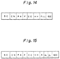
- the format of the conventional home address HA is as shown in Fig. 14.
- One home address HA is included in each track, to represent the physical position of the track or the state of the track.
- one home address consists of a skip control SC, a cell number CN, a physical address PA, a flag, F, a cylinder number CC, a head number HH, a fill data Fill, and an error correction code ECC.
- the skip control SC is as follows. Namely, a track having a damage or defect thereon (for example, a magnetic defect) is not deemed as a no-good track, but, instead, a reading or writing of data is carried out on the track having the damage, by avoiding the defective portion.
- the skip control SC is data for indicating the position of the defective portion. Usually, two bytes are used to record each of seven data in the sequence of SC1, SC2, .., and SC7. Each two bytes of the skip control SCn, where n is 1, 2, ..., or 7, represents the distance from the index mark IM indicating the beginning of the track to the center of the n-th defective portion is expressed by the number of cells.
- the cell number CN represents the cell number of a cell just before the cell at which a synchronization byte (Sync Byte) of the home address HA exists.
- the physical address PA represents a physical cylinder number and a head number of the track.
- the flag F represents the state or the attribute of the track.
- the format of the count area C is as shown in Fig. 15.
- the count area C includes, first, a skip control SC, then a cell number CN, and further, a physical address PA, a flag F, a cylinder number CC, a head number HH, a record number R, a key length KL, a data length DL, and an error correction code ECC.
- Data is recorded on the disk in accordance with the above-mentioned data format of the disk track.
- the disk track is divided into cells, each of which is a unit with a certain number of bytes, for example, 32 bytes.
- the active disk system has a track divided by cells, having a unit of 32 bytes, and each track consisting of 1554 cells, but the new disk system has a track divided by cells, each of which is a unit of 34 bytes, and each track consists of 1944 cells.
- the new disk system has a higher disk rotating speed and a different number of cells in the gap G, in comparison with the active disk system.
- Figure 1 is a principal diagram of the present invention.
- 2 represents a disk control device, 4 a transfer circuit to transfer data between the disk control device and a host device, 5 a data frame register (DFR), 6 a transfer buffer, 7 a bus register, 8 a device interface, 9 an internal register group, 10 an MPU, 11 a control storage, 12 a physical cell number register (PCN register), 13 a logical cell number register (LCN register), and 14 a skip control register(SC register).
- DFR data frame register
- SC register a skip control register
- the present invention has the following mode of operation.
- the disk control device 2 controls the device (disk device) in accordance with a command from the host device, and carries out a disk track emulation for the host device. This process is carried out by the MPU 10 by taking out programs and so forth stored in the control storage 11.
- data transferred from the host device is once stored in the transfer buffer 6, and the MPU 10 sets a physical position data (PCN) and a logical position data (LCN) in the transfer buffer 6.
- PCN physical position data
- LCDN logical position data
- the afore-mentioned data (PCN,LCN) are stored in the physical cell position register 12 and the logical cell position register 13 in the internal register group 9, and are assumed to be a data write-in current position of the disk track.
- the data in the transfer buffer 6 is sent to the device to be written to a write-in position of the target track.
- the preparation for the next writing operation is effected by adding the number of cells to which data is written to the above-mentioned data (PCN,LCN).
- the physical cell position data the physical cell position data in the data format of the disk track is used; and as the logical cell position data (LCN), the cell position data (the position calculated in accordance with the cell data of the active data format) to be emulated is used.
- the logical cell position data the cell position data (the position calculated in accordance with the cell data of the active data format) to be emulated is used.
- the value of the logical cell position data (LCN) is not changed even when there is a damaged position, and this data (LCN) is used as the compatible cell pcsition data for the host device.
- the compatibility of the data format of the disk track can be maintained for the host device, and thus disk track emulation becomes possible.
- 2A represents a magnetic disk control device
- 3A a magnetic disk device
- 8A a bidirectional control interface (BCI).
- the magnetic disk control device 2A is provided with a transfer circuit 4 for transferring data between the host device 1 and the disk control device 2A.
- the disk control device 2A further includes a data frame register (DFR) 5, a transfer buffer 6, a bus register (BUS register ) 7, a bidirectional control interface (BCI) 8A, an internal register group 9, an MPU 10, and a control storage 11.
- DFR data frame register
- BUS register bus register
- BCI bidirectional control interface
- the internal control register group 9 includes a physical cell number register (PCN register) 12, a logical cell number register (LCN register) 13, and a skip control register (SC register) 14.
- PCN register physical cell number register
- LN register logical cell number register
- SC register skip control register
- the transfer circuit 4 transfers data or process commands from or to the magnetic disk control device 2A to or from the host device 1, and the data frame register 5 receives commands from the host device 1 (the MPU 10 receives commands from this register).
- the transfer buffer 6 is a data storing buffer used for data transfers between the host device 1 and the magnetic disk device 3A (the MPU 10 can read or write data in or from this buffer).
- the bus register 7 is a register used by the MPU 10 to issue a process command to the magnetic disk device 3A, and to acknowledge a response from the magnetic disk device 3A.
- the control storage 11 stores programs, various data and so forth used by the magnetic disk control device 2A; for example, the data of the data formats of the active and the new disk tracks (such as the number of cells in the recording area or the gap).
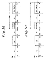
- the data format of the disk track is described with reference to Figs. 3A, 3B, 4A, 4B, 5A, and 5B.
- the data format of the disk track in the active magnetic disk system (A) and the data format of the disk track in the new disk system (B) are comparatively shown.
- a data format without a key area is used in which the numerals in the figures represent cell numbers which are the same as the number of cells counted from a start point, i.e., an index mark IM indicating the beginning point of a track.
- the other areas are constituted as illustrated.
- the other areas are constituted as illustrated.
- the conventional format of the home address HA is as shown in Fig. 6A.
- a skip control SC 14 bytes
- a cell number CN 2 bytes
- a physical address PA 3 bytes
- a flag F (1 byte
- a cylinder number CC 2 bytes
- a head number HH 2 bytes
- a fill data 4 bytes
- an error correction code ECC (12 bytes)
- the skip control SC is an area for recording damaged position data
- the fill data Fill is an area for recording dummy embedding data.
- a physical cell number PCN (2 bytes), a reserve (unused) Rsv (2 bytes), a skip control SC (14 bytes), a logical cell number LCN (2 bytes), a physical address PA (3 bytes), a flag F (1 byte), a cylinder number CC (2 bytes), a head number HH (2 bytes), fill data Fill (4 bytes), and an error correction code ECC (12 bytes) are sequentially arranged.
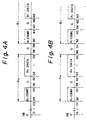
- the conventional format of the count area is constituted as shown in Fig. 7A.
- the active or conventional format is constituted, as shown in Fig. 7A, a skip control SC (14 bytes), a cell number CN (2 bytes), a physical address PA (3 bytes), a flag F (1 byte), a cylinder number CC (2 bytes), a head number HH (2 bytes), a record number R (1 byte), a key length KL (1 byte), a data length DL (2 bytes), and an error correction code ECC (12 bytes) are sequentially arranged.
- a physical cell number PCN (2 bytes), a reserve (unused) Rsv (2 bytes), a skip control SC (14 bytes), a logical cell number LCN (2 bytes), a physical address PA (3 bytes), a flag F (1 byte), a cylinder number CC (2 bytes), a head number HH (2 bytes), a record number R (1 byte), a key length KL (1 byte), a data length DL (2 bytes), and an error correction code ECC (12 bytes) are sequentially arranged.
- a compatibility is maintained between the active or the conventional data format of the disk track and the new data format of the disk track. This maintenance of the compatibility of the disk tracks is referred to as a disk track emulation.
- the new formats of the home address and the count area are determined as shown in Fig. 6B and Fig. 7B.
- the different areas between the active format and the format of the present invention are the physical cell number PCN and the logical cell number LCN. Note, since the reserve Rsv is unused it does not relate to this difference.
- the data processing between the magnetic disk control device 2A and the magnetic disk device 3A is carried out in accordance with the new data formats shown in Fig. 6B and Fig. 7B.
- the above-mentioned physical cell number PCN is a physical cell position.
- the logical cell number LCN is a compatible cell position in order to maintain the compatibility between the host device 1 and the magnetic disk control device 2A.
- the logical cell number LCN is the same as the cell number CN in the active format.
- the magnetic disk control device 2A can use the logical cell number LCN for the host device 1 to emulate the disk format of the active or conventional disk track.
- the data recording position on the actual magnetic disk device or the skip control data for avoiding defects in the magnetic disk device are processed by using the physical cell number PCN.
- the data capacity (track capacity) for possible storage per track can be virtually emulated.
- a basic format When data is to be written to the disk, first a basic format must be prepared with respect to the data format of the disk track.
- the preparation of the basic format is an initialization process of the data format.
- the initialization of the data format of the disk track is made by writing the home address HA and the record R 0 ( track description record) to the disk.
- a command (CCW) is sent from the host device 1 to the magnetic disk control device 2A.
- the command can be any of "SEEK”, “SET FILE MASK”, “DIAGNOSTIC WRITE HA”, and “WRITE R 0 ".
- the magnetic disk control device 2A controls the magnetic disk device 3A to carry out the initialization process.
- the magnetic disk control device 2A which has received the above-mentioned commands "SEEK” and "SET FILE MASK" from the host device, outputs an instruction to the magnetic disk device 3A to position the head of the magnetic disk device 3A at the target track.
- the magnetic disk control device 2A After recognition of the completion of the positioning by the magnetic disk device 3A, the magnetic disk control device 2A receives the command "DIAGNOSTIC WRITE HA" from the host device 1.
- the data sent from the host device 1 at this time has the active format shown in Fig. 6A. Namely, the data sent from the host device 1 has a format compatible with the active format. Therefore, the skip control SC (the damaged position data) in the data from the host device 1 is written by the physical cell position number.
- the data shown in Fig. 6A and sent from the host device 1 to the magnetic disk control device 2A is once stored in the transfer buffer 6 in which the current writing position is set as the physical cell position data PCN and the logical cell position data LCN, and the same values are also stored in the internal register group 9.
- damaged position data (maximum seven) is stored in the internal register group 9 to be used for correcting, in the following data writing operation, the writing positions with respect to the damaged positions.
- the physical cell position data PCN is added to the data sent from the host device 1 and stored in the transfer buffer 6.
- the added data is then sent from the transfer buffer 6 to the magnetic disk device 3A, and is written on the disk track of the magnetic disk device 3A.
- preparation for the next writing is carried out by adding the number of cells of the home address, i.e., 2, to the PCN and to the LCN. Note that, when there a defect is found in the disk track during the above-mentioned data writing operation, a process is carried out to correct the physical cell position data PCN.
- the data is written in the count area, and then a value for the gap between the cells 34 and 42 is added to the PCN and LCN. Then, by using these corrected values of the PCN and LCN, data is written in the data area.
- the number of cells in the written data area and in the gap between the cells 44 and 51 are added to the values of the PCN and the LCN for preparing the next writing operation.
- a logic index is generated.
- the data length and the gap length are included in the data of the count area sent from the host device when the data is to be written. If the corrected LCN exceeds the position of the physical index in the active data format, the data writing operation is not carried out and the host device 1 is informed of an error.
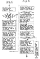
- a command (CCW) "SEEK” and a command “SET FILE MASK” (CCW) is sent from the host device 1 to the magnetic disk control device 2A, to position the head at the target track on the magnetic disk device 3A.
- This command is once stored in the data frame register 5, and then incorporated into the MPU 10.
- a process is carried out by using a program in the control storage 11.
- the MPU 10 receives the commands "SEEK” and "SET FILE MASK", the track to be processed is determined (S1).
- the positioning operation is performed by the magnetic disk device 3A only.
- the magnetic disk control device 2A receives an interruption indicating the completion of the positioning, from the magnetic disk device 3A (S5), whereby the magnetic disk device 3A and the host device 1 are again combined (S6).
- the MPU 10 receives a chain command (CCW) from the host device 1 (S7), and depending on the type of command, the following processes are carried out.
- CCW chain command
- a process as shown in Fig. 9 is carried out.
- the magnetic disk control device 2A which has received the above-mentioned command, then receives from the host device 1 data to be written on the magnetic disk device 3A (S8).
- This data (SC, LCN, PA, F, CC, and HH) is in the conventional data format of the home address HA shown in Fig. 6A.
- the data consists of a part (a) in the new data format shown in Fig. 6B, and is temporarily stored in the transfer buffer 6.
- the MPU 10 sets the physical cell number PCN 20 and the logical cell number LCN 14 in the transfer buffer 6 (S9).
- the host device 1 can normally access the disk device by the logical cell position in the active (conventional) data format, and only at the time when the skip control SC is used, is the skip control SC (damaged position data) in the active format shown in Fig. 6A sent as a physical cell position from the host device.
- the value of the PCN is 20, which is the cell number just before the home address shown in Fig. 3B, and the value of the LCN is 14, which is just prior to the home address HA shown in Fig. 3A.
- PCN register physical cell number register
- LCN register logical cell number register
- SC data are stored in the skip control register (SC register) 14.
- SC register up to seven SC data per track can be recorded. SC data above seven cannot be recorded and such a track is treated as unusable. Therefore, as there is a maximum of seven SC data, seven SC registers 14 are used.
- the MPU 10 determines whether or not a defect has been written as the skip control SC sent from the host device 1. If there is a defect (S13), the MPU 10 sends an instruction, through the bus register 7 to the magnetic disk device 3A, to skip three cells for one defect (S14).
- the value of the PCN set in the transfer buffer 6 and the value of the PCN set in the PCN register 12 are modified so that they have values in which the number of three cells is added for one defect to each value (if there is one defect, +3 is added to the PCN; if there are two defects, +6 is added) (S15).
- the value of the logical cell number LCN is not changed (because the logical cell position is not influenced by the data of the defect). Also, if there is no defect, the above-mentioned processes S14 and S15 are not carried out.
- an instruction for writing the home address HA is issued from the MPU 10 to the magnetic disk device 3A, and the data in the transfer buffer 6 is sent through the bidirectional control interface (BCI) 8A (S16). Then, to change the values in the physical cell number register 12 and the logical cell number register 13 to the value at the last portion of the home address HA, for preparing the next process, two is added to these values PCN and LCN, because the number of cells in the home address HA is two (S17).
- Fig. 10 When the command from the host device 1 is "SEARCH ID EQ", the process shown in Fig. 10 is carried out.
- the magnetic disk control device 2A After receiving the command "SEARCH ID EQ", the magnetic disk control device 2A receives, from the host device 1, 5 bytes data to be searched. The 5 bytes data is stored in the transfer buffer 6 (S18).
- This 5 bytes data is the data (CC, HH, and R) in the part (b) in the new format of the counter area shown in Fig. 7B.
- the data of the part (b) is included in the conventional format shown in Fig. 7A, and therefore, is sent from the host device 1 for a comparing of data.
- the MPU 10 issues a command to read the first count area(S19), to the magnetic disk device 3A, and the data read from the count area is stored in the transfer buffer 6 (S20), and the data in the transfer buffer 6 is stored in the internal register group 9 (S21). Then, the above-mentioned 5 bytes data sent from the host device 1 and the 5 byte data read from the count area in the magnetic disk device 3A are compared (S22).
- the magnetic disk control device 2A which has received the above-mentioned command, recognizes the position at the current track (S27) to determine whether or not the position at the current track is on the last part of the home address HA or of the data area (S28).
- the values of the logical cell number and the physical cell number are corrected to the last part of the data area, by adding to the PCN and the LCN the length of the data area of the previous record and the gap followed by the data area.
- each register PCN register and the LCN register
- S29 the value of each register
- the MPU 10 issues an instruction to the magnetic disk device 3A to skip to the end part of the data area (S30).
- the magnetic disk control device 2A receives data to be written into the count area from the host device 1, and stores the data to the transfer buffer 6.
- the data received at this time is the data of the part (c) (CC, H, , R, KL, and DL) in the new format of the count area shown in Fig. 7B.
- the data of the part (b) is included in the conventional format shown in Fig. 7A, and therefore, is sent from the host device 1 for a comparing of data.
- the physical cell number PCN and the logical cell number LCN which are to be added to the count area, are taken out from the registers 12 and 13, and then the number of cells in the next gap after the home address or the data area is added to the PCN and the LCN taken out from the registers 12 and 13, and the corrected PCN and LCN are stored in the registers 12 and 13. Simultaneously, to prepare data to be written in the count area, the corrected PCN and LCN are written, with the data in the skip control register 14, to the transfer buffer 6 (S32).
- the MPU 10 checks whether or not skip control data (SC data) corresponding to the count area exists (S33). If SC data exists, an instruction to skip 3 cells for each defect is issued to the magnetic disk device 3A.
- SC data skip control data
- the PCN in the transfer buffer 6 and the value in the physical cell number register 12 are updated by adding the number of skipped cells (S36).0
- the length of the data area included in the transferred count area, and the necessary gap, are calculated as a compatible track, to output the logical cell number of the last part in the data area (S37), and it is determined whether or not the calculated result is larger than the position of the logical index (in this example, as shown in Fig. 5, it is 1554) (S38).
- the data in the data area is received from the host device 1 and is written to the magnetic disk device 3A.
- corrections are made for each field, by writing the values of the PCN and the LCN into the physical cell number register 12 and the logical cell number register 13 (S41).
- the correction due to the defect is carried out based on the SC data.
Landscapes
- Engineering & Computer Science (AREA)
- Theoretical Computer Science (AREA)
- Human Computer Interaction (AREA)
- Physics & Mathematics (AREA)
- General Engineering & Computer Science (AREA)
- General Physics & Mathematics (AREA)
- Multimedia (AREA)
- Signal Processing (AREA)
- Signal Processing For Digital Recording And Reproducing (AREA)
Claims (6)
- Plattenspuremulationssystem zum Wahren der Kompatibilität zwischen einem ersten Datenformat einer Plattenspur in einer ersten Plattenvorrichtung (3) und einem zweiten Datenformat einer Plattenspur in einer zweiten Plattenvorrichtung (3);welche Plattensteuervorrichtung (2) umfaßt:wobei sich das zweite Datenformat von dem ersten Datenformat unterscheidet;das System eine Hostvorrichtung (1), die zweite Plattenvorrichtung (3) und eine Plattensteuervorrichtung (2) enthält, die zwischen der Hostvorrichtung (1) und der zweiten Plattenvorrichtung (3) verbunden ist;jede Plattenspur eine Vielzahl von Zellen umfaßt, von welchen Zellen jede eine Vielzahl von Bytes umfaßt;die Hostvorrichtung (1) Daten gemäß dem ersten Datenformat behandelt, die Plattensteuervorrichtung (2) und die zweite Plattenvorrichtung (3) Daten gemäß dem zweiten Datenformat behandeln;dadurch gekennzeichnet, daß die Daten, die in den jeweiligen Plattenvorrichtungen in ihren jeweiligen Formaten zu speichern sind, in beiden Formaten als Datensätze mit variabler Länge beibehalten werden.ein Erzeugungsmittel physikalischer Zellenpositionsdaten zum Erzeugen physikalischer Zellenpositionsdaten (PCN), die die Position der Zelle, auf die zuzugreifen ist, gemäß dem zweiten Datenformat darstellen, als Reaktion auf eine Zugriffsoperation entweder durch die Plattensteuervorrichtung (2) oder durch die zweite Plattenvorrichtung (3);
undein Erzeugungsmittel logischer Zellenpositionsdaten zum Erzeugen logischer Zellenpositionsdaten (LCN), die die Position der Zelle, auf die zuzugreifen ist, gemäß dem ersten Datenformat darstellen, zum Zugriff durch die Hostvorrichtung (1);welche physikalischen Zellenpositionsdaten und welche logischen Zellenpositionsdaten (LCN) in den Spurdaten gemäß dem zweiten Datenformat enthalten sind;bei dem sich die zwei Formate darin unterscheiden, daß jedes eine verschiedene Anzahl von Zellen pro Spur und/oder eine verschiedene Anzahl von Bytes pro Zelle hat, - Plattenspuremulationssystem nach Anspruch 1, bei dem eine Spur auf der Plattenvorrichtung einen Hausadressen-(HA)-Bereich enthält, zum Aufzeichnen von Hausadressendaten zum Bezeichnen wenigstens der Position der Spur, und einen Zählbereich, der für jeden Datensatz in der Spur vorgesehen ist, zum Bezeichnen der physikalischen Position des Datensatzes, welche physikalischen Zellenpositionsdaten und welche logischen Zellenpositionsdaten in den Hausadressenbereich und den Zählbereich geschrieben werden.
- Plattenspuremulationssystem nach Anspruch 1 oder Anspruch 2, bei dem die logischen Zellenpositionsdaten durch Daten beschädigter Positionen auf der Plattenvorrichtung nicht beeinflußt werden.
- Plattenspuremulationssystem nach Anspruch 1, 2 oder 3, bei dem:während der Steuerung einer Plattenvorrichtung (3) ein Prozeß unter Verwendung der physikalischen Zellenpositionsdaten ausgeführt wird; undwährend einer Übertragung von Daten zu der Hostvorrichtung (1) ein Prozeß unter Verwendung der logischen Zellenpositionsdaten ausgeführt wird.
- Plattenspuremulationssystem nach irgendeinem vorhergehenden Anspruch, ferner mit:einem Prüfmittel zum Prüfen von Daten beschädigter Positionen, die als physikalische Zellenpositionsdaten von der Hostvorrichtung (1) übertragen wurden, während Daten in eine Plattenspur geschrieben werden;einem Schreibmittel zum Schreiben der Daten, wenn ein Defekt an einer Datenschreibposition vorliegt, indem die Schreibposition auf der Plattenspur, auf der Basis der Daten beschädigter Positionen (SC), durch eine vorbestimmte Anzahl von Zellen übersprungen wird; undeinem Addiermittel zum Addieren der Anzahl von Zellen für das Überspringen zu den physikalischen Zellenpositionsdaten (PCN), die die gegenwärtige Position auf der Plattenspur angeben;wodurch die Position des Defektes korrigiert wird.
- Plattenspuremulationssystem nach Anspruch 4 oder 5, ferner mit:einem Entnahmemittel zum Entnehmen, wenn Daten auf die Plattenspur geschrieben werden, von Längendaten geschriebener Daten, die in dem Zählbereich enthalten sind und von der Hostvorrichtung gesendet wurden; undeinem Addiermittel zum Addieren der Anzahl von Zellen des Datenbereiches dieser Daten und der Anzahl von Zellen einer Lücke danach zu den logischen Zellenpositionsdaten (LCN); wodurchdie Position der letzten logischen Zelle, auf die die Daten zu schreiben sind, berechnet wird; und, falls das Resultat die Zellenposition eines physikalischen Indexes überschreitet, der das Ende der physikalischen Spur in dem aktiven Format angibt, die Hostvorrichtung von einem Fehler informiert wird und die Daten nicht geschrieben werden.
Applications Claiming Priority (2)
| Application Number | Priority Date | Filing Date | Title |
|---|---|---|---|
| JP2334167A JP2761289B2 (ja) | 1990-11-30 | 1990-11-30 | ディスクトラックエミュレーション方法 |
| JP334167/90 | 1990-11-30 |
Publications (3)
| Publication Number | Publication Date |
|---|---|
| EP0488700A2 EP0488700A2 (de) | 1992-06-03 |
| EP0488700A3 EP0488700A3 (en) | 1992-09-09 |
| EP0488700B1 true EP0488700B1 (de) | 1998-03-04 |
Family
ID=18274292
Family Applications (1)
| Application Number | Title | Priority Date | Filing Date |
|---|---|---|---|
| EP91310974A Expired - Lifetime EP0488700B1 (de) | 1990-11-30 | 1991-11-28 | Plattenspuremulationssystem und -verfahren |
Country Status (4)
| Country | Link |
|---|---|
| US (1) | US5590311A (de) |
| EP (1) | EP0488700B1 (de) |
| JP (1) | JP2761289B2 (de) |
| DE (1) | DE69129006T2 (de) |
Families Citing this family (11)
| Publication number | Priority date | Publication date | Assignee | Title |
|---|---|---|---|---|
| CA2124754C (en) * | 1993-06-30 | 2005-06-28 | Mark Zbikowski | Storage of file data on disk in multiple representations |
| US5613105A (en) * | 1993-06-30 | 1997-03-18 | Microsoft Corporation | Efficient storage of objects in a file system |
| JP3264465B2 (ja) * | 1993-06-30 | 2002-03-11 | 株式会社日立製作所 | 記憶システム |
| JP3583829B2 (ja) * | 1995-04-13 | 2004-11-04 | 株式会社日立製作所 | 外部記憶サブシステムの制御方法および制御装置 |
| US5784216A (en) * | 1995-11-16 | 1998-07-21 | Seagate Technology, Inc. | Method and apparatus for recording defective track identification information in a disk drive |
| US6233660B1 (en) * | 1996-02-16 | 2001-05-15 | Emc Corporation | System and method for emulating mainframe channel programs by open systems computer systems |
| US5778359A (en) * | 1996-04-18 | 1998-07-07 | Davox Corporation | System and method for determining and verifying a file record format based upon file characteristics |
| US6167498A (en) * | 1997-10-02 | 2000-12-26 | Cirrus Logic, Inc. | Circuits systems and methods for managing data requests between memory subsystems operating in response to multiple address formats |
| US6324604B1 (en) | 1998-07-07 | 2001-11-27 | Emc Corporation | Magnetic disk storage for storing data in disk block size from fixed length of host block in non-integer multiple of the disk block size |
| CN1122281C (zh) * | 2001-06-30 | 2003-09-24 | 深圳市朗科科技有限公司 | 一种多功能半导体存储装置 |
| US7814664B2 (en) * | 2007-05-21 | 2010-10-19 | Irwin Industrial Tool Company | Folding utility knife |
Family Cites Families (23)
| Publication number | Priority date | Publication date | Assignee | Title |
|---|---|---|---|---|
| US3997876A (en) * | 1972-06-07 | 1976-12-14 | International Business Machines Corporation | Apparatus and method for avoiding defects in the recording medium within a peripheral storage system |
| US4223390A (en) * | 1976-02-02 | 1980-09-16 | International Business Machines Corporation | System and method for attaching magnetic storage devices having dissimilar track capacities and recording formats |
| US4533996A (en) * | 1982-02-23 | 1985-08-06 | International Business Machines Corporation | Peripheral systems accommodation of guest operating systems |
| US4434487A (en) * | 1981-10-05 | 1984-02-28 | Digital Equipment Corporation | Disk format for secondary storage system |
| US4805090A (en) * | 1985-09-27 | 1989-02-14 | Unisys Corporation | Peripheral-controller for multiple disk drive modules having different protocols and operating conditions |
| US4746998A (en) * | 1985-11-20 | 1988-05-24 | Seagate Technology, Inc. | Method for mapping around defective sectors in a disc drive |
| JPS62151259A (ja) * | 1985-12-25 | 1987-07-06 | Ube Ind Ltd | 射出成形装置における成形品の良否判別方法 |
| US4775969A (en) * | 1986-05-15 | 1988-10-04 | Aquidneck Systems International, Inc. | Optical disk storage format, method and apparatus for emulating a magnetic tape drive |
| US4680653A (en) * | 1986-05-22 | 1987-07-14 | International Business Machines Corporation | Rotating storage device track format emulation |
| JPS63311427A (ja) * | 1987-06-15 | 1988-12-20 | Fujitsu Ltd | シ−クヘッドコマンド実行方式 |
| JPS63316121A (ja) * | 1987-06-19 | 1988-12-23 | Fujitsu Ltd | トラックエミュレ−ション方式 |
| JPS641187A (en) * | 1987-06-23 | 1989-01-05 | Fujitsu Ltd | Control system for track positioning |
| JPH0799608B2 (ja) * | 1987-08-19 | 1995-10-25 | 富士通株式会社 | 磁気ディスク装置のトラックエミレ−ション方式 |
| JPS6470818A (en) * | 1987-09-11 | 1989-03-16 | Fujitsu Ltd | Data recording system for semiconductor disk device |
| US4928192A (en) * | 1987-12-23 | 1990-05-22 | Konica Corporation | Process for identifying disks and automatically configuring a disk drive system |
| JPH01306917A (ja) * | 1988-05-20 | 1989-12-11 | Internatl Business Mach Corp <Ibm> | 記憶制御方法及び装置 |
| US5301304A (en) * | 1988-05-20 | 1994-04-05 | International Business Machines Corporation | Emulating records in one record format in another record format |
| US5113512A (en) * | 1988-06-21 | 1992-05-12 | Matsushita Electric Industrial Co., Ltd. | System for managing a storage medium reducing physical space needed |
| US5075804A (en) * | 1989-03-31 | 1991-12-24 | Alps Electric Co., Ltd. | Management of defect areas in recording media |
| US5018095A (en) * | 1990-02-15 | 1991-05-21 | Seagate Technology, Inc. | Universal disk drive type emulation for IBM PC-AT computers |
| JP2831087B2 (ja) * | 1990-03-19 | 1998-12-02 | 株式会社日立製作所 | データ記憶システム |
| US5210866A (en) * | 1990-09-12 | 1993-05-11 | Storage Technology Corporation | Incremental disk backup system for a dynamically mapped data storage subsystem |
| US5297124A (en) * | 1992-04-24 | 1994-03-22 | Miltope Corporation | Tape drive emulation system for a disk drive |
-
1990
- 1990-11-30 JP JP2334167A patent/JP2761289B2/ja not_active Expired - Lifetime
-
1991
- 1991-11-28 DE DE69129006T patent/DE69129006T2/de not_active Expired - Fee Related
- 1991-11-28 EP EP91310974A patent/EP0488700B1/de not_active Expired - Lifetime
-
1994
- 1994-06-14 US US08/259,558 patent/US5590311A/en not_active Expired - Fee Related
Also Published As
| Publication number | Publication date |
|---|---|
| US5590311A (en) | 1996-12-31 |
| JP2761289B2 (ja) | 1998-06-04 |
| EP0488700A3 (en) | 1992-09-09 |
| JPH04205970A (ja) | 1992-07-28 |
| DE69129006T2 (de) | 1998-06-25 |
| EP0488700A2 (de) | 1992-06-03 |
| DE69129006D1 (de) | 1998-04-09 |
Similar Documents
| Publication | Publication Date | Title |
|---|---|---|
| KR900004758B1 (ko) | 대용량 기억 디스크 드라이브 불량 매체 처리방법 | |
| EP0680655B1 (de) | Verfahren zur aufgabenzuordnung zwischen zwei armen die auf der gleichen magnetplatte auf einem einzelplattenantrieb benutzt werden | |
| EP0488700B1 (de) | Plattenspuremulationssystem und -verfahren | |
| GB2404830A (en) | Data with multiple sets of error correction codes | |
| EP0219261B1 (de) | Anordnung zur Informationsaufzeichnung und Wiedergabe | |
| US6710960B1 (en) | Information storage apparatus and method of controlling the same | |
| US5084789A (en) | "Parallel transfer type disk system" | |
| US5461719A (en) | Method for recording/reproducing information on recording medium in accordance with parameters stored in memory to allow sectors of different data capacities to collectively exist | |
| EP0347032A2 (de) | Satzstruktur-Emulation | |
| US6943973B1 (en) | Management method for reproduction error and a disk drive making use of the management method | |
| KR100659915B1 (ko) | 데이터 전송 방법 및 장치 | |
| JP3132677B2 (ja) | 情報記録再生方法 | |
| EP1047061A1 (de) | Informationsaufzeichnungs- und -wiedergabegerät und Plattenlaufwerk | |
| US20060007590A1 (en) | Magnetic disk apparatus | |
| US5091909A (en) | Method for writing/reading of data in magnetic disk subsystem | |
| JP2637594B2 (ja) | 情報記録再生装置 | |
| JP2644218B2 (ja) | 磁気記録方法 | |
| US4647991A (en) | Disk channel controller | |
| EP0080878A2 (de) | Cache-Speicher und Steuerungsverfahren für die Verwendung mit Magnetscheiben | |
| JP2852935B2 (ja) | 情報再生装置 | |
| JP2544327B2 (ja) | 磁気デイスク制御装置 | |
| JPH0664519B2 (ja) | 可換記録媒体アクセス方式 | |
| JPH0528651A (ja) | 情報記録再生装置 | |
| JPS6041124A (ja) | 磁気デイスク制御装置 | |
| JPH0594672A (ja) | 情報記録再生装置 |
Legal Events
| Date | Code | Title | Description |
|---|---|---|---|
| PUAI | Public reference made under article 153(3) epc to a published international application that has entered the european phase |
Free format text: ORIGINAL CODE: 0009012 |
|
| AK | Designated contracting states |
Kind code of ref document: A2 Designated state(s): DE FR GB |
|
| PUAL | Search report despatched |
Free format text: ORIGINAL CODE: 0009013 |
|
| AK | Designated contracting states |
Kind code of ref document: A3 Designated state(s): DE FR GB |
|
| 17P | Request for examination filed |
Effective date: 19921124 |
|
| 17Q | First examination report despatched |
Effective date: 19950529 |
|
| GRAG | Despatch of communication of intention to grant |
Free format text: ORIGINAL CODE: EPIDOS AGRA |
|
| GRAG | Despatch of communication of intention to grant |
Free format text: ORIGINAL CODE: EPIDOS AGRA |
|
| GRAH | Despatch of communication of intention to grant a patent |
Free format text: ORIGINAL CODE: EPIDOS IGRA |
|
| GRAH | Despatch of communication of intention to grant a patent |
Free format text: ORIGINAL CODE: EPIDOS IGRA |
|
| GRAA | (expected) grant |
Free format text: ORIGINAL CODE: 0009210 |
|
| AK | Designated contracting states |
Kind code of ref document: B1 Designated state(s): DE GB |
|
| REF | Corresponds to: |
Ref document number: 69129006 Country of ref document: DE Date of ref document: 19980409 |
|
| EN | Fr: translation not filed | ||
| PLBE | No opposition filed within time limit |
Free format text: ORIGINAL CODE: 0009261 |
|
| STAA | Information on the status of an ep patent application or granted ep patent |
Free format text: STATUS: NO OPPOSITION FILED WITHIN TIME LIMIT |
|
| 26N | No opposition filed | ||
| REG | Reference to a national code |
Ref country code: GB Ref legal event code: IF02 |
|
| PGFP | Annual fee paid to national office [announced via postgrant information from national office to epo] |
Ref country code: GB Payment date: 20051123 Year of fee payment: 15 |
|
| PGFP | Annual fee paid to national office [announced via postgrant information from national office to epo] |
Ref country code: DE Payment date: 20051124 Year of fee payment: 15 |
|
| PG25 | Lapsed in a contracting state [announced via postgrant information from national office to epo] |
Ref country code: DE Free format text: LAPSE BECAUSE OF NON-PAYMENT OF DUE FEES Effective date: 20070601 |
|
| GBPC | Gb: european patent ceased through non-payment of renewal fee |
Effective date: 20061128 |
|
| PG25 | Lapsed in a contracting state [announced via postgrant information from national office to epo] |
Ref country code: GB Free format text: LAPSE BECAUSE OF NON-PAYMENT OF DUE FEES Effective date: 20061128 |