EP0488811A2 - Appareil d'enregistrement et de reproduction magnétiques - Google Patents
Appareil d'enregistrement et de reproduction magnétiques Download PDFInfo
- Publication number
- EP0488811A2 EP0488811A2 EP91311154A EP91311154A EP0488811A2 EP 0488811 A2 EP0488811 A2 EP 0488811A2 EP 91311154 A EP91311154 A EP 91311154A EP 91311154 A EP91311154 A EP 91311154A EP 0488811 A2 EP0488811 A2 EP 0488811A2
- Authority
- EP
- European Patent Office
- Prior art keywords
- equalising
- reproduced
- lower band
- output
- signal
- Prior art date
- Legal status (The legal status is an assumption and is not a legal conclusion. Google has not performed a legal analysis and makes no representation as to the accuracy of the status listed.)
- Granted
Links
Images



Classifications
-
- G—PHYSICS
- G11—INFORMATION STORAGE
- G11B—INFORMATION STORAGE BASED ON RELATIVE MOVEMENT BETWEEN RECORD CARRIER AND TRANSDUCER
- G11B5/00—Recording by magnetisation or demagnetisation of a record carrier; Reproducing by magnetic means; Record carriers therefor
- G11B5/02—Recording, reproducing, or erasing methods; Read, write or erase circuits therefor
- G11B5/027—Analogue recording
- G11B5/035—Equalising
-
- G—PHYSICS
- G11—INFORMATION STORAGE
- G11B—INFORMATION STORAGE BASED ON RELATIVE MOVEMENT BETWEEN RECORD CARRIER AND TRANSDUCER
- G11B5/00—Recording by magnetisation or demagnetisation of a record carrier; Reproducing by magnetic means; Record carriers therefor
- G11B5/008—Recording on, or reproducing or erasing from, magnetic tapes, sheets, e.g. cards, or wires
- G11B5/00813—Recording on, or reproducing or erasing from, magnetic tapes, sheets, e.g. cards, or wires magnetic tapes
- G11B5/00847—Recording on, or reproducing or erasing from, magnetic tapes, sheets, e.g. cards, or wires magnetic tapes on transverse tracks
- G11B5/0086—Recording on, or reproducing or erasing from, magnetic tapes, sheets, e.g. cards, or wires magnetic tapes on transverse tracks using cyclically driven heads providing segmented tracks
-
- G—PHYSICS
- G11—INFORMATION STORAGE
- G11B—INFORMATION STORAGE BASED ON RELATIVE MOVEMENT BETWEEN RECORD CARRIER AND TRANSDUCER
- G11B5/00—Recording by magnetisation or demagnetisation of a record carrier; Reproducing by magnetic means; Record carriers therefor
- G11B5/02—Recording, reproducing, or erasing methods; Read, write or erase circuits therefor
- G11B5/09—Digital recording
-
- H—ELECTRICITY
- H03—ELECTRONIC CIRCUITRY
- H03G—CONTROL OF AMPLIFICATION
- H03G5/00—Tone control or bandwidth control in amplifiers
- H03G5/02—Manually-operated control
- H03G5/04—Manually-operated control in untuned amplifiers
- H03G5/10—Manually-operated control in untuned amplifiers having semiconductor devices
-
- G—PHYSICS
- G11—INFORMATION STORAGE
- G11B—INFORMATION STORAGE BASED ON RELATIVE MOVEMENT BETWEEN RECORD CARRIER AND TRANSDUCER
- G11B33/00—Constructional parts, details or accessories not provided for in the other groups of this subclass
- G11B33/12—Disposition of constructional parts in the apparatus, e.g. of power supply, of modules
- G11B33/121—Disposition of constructional parts in the apparatus, e.g. of power supply, of modules the apparatus comprising a single recording/reproducing device
- G11B33/122—Arrangements for providing electrical connections, e.g. connectors, cables, switches
-
- G—PHYSICS
- G11—INFORMATION STORAGE
- G11B—INFORMATION STORAGE BASED ON RELATIVE MOVEMENT BETWEEN RECORD CARRIER AND TRANSDUCER
- G11B5/00—Recording by magnetisation or demagnetisation of a record carrier; Reproducing by magnetic means; Record carriers therefor
- G11B5/48—Disposition or mounting of heads or head supports relative to record carriers ; arrangements of heads, e.g. for scanning the record carrier to increase the relative speed
- G11B5/52—Disposition or mounting of heads or head supports relative to record carriers ; arrangements of heads, e.g. for scanning the record carrier to increase the relative speed with simultaneous movement of head and record carrier, e.g. rotation of head
- G11B5/53—Disposition or mounting of heads on rotating support
Definitions
- This invention relates to magnetic recording and reproducing apparatus, and more particularly to such an apparatus arranged for reproducing an information signal recorded on a magnetic tape by scanning the magnetic tape with a rotary head by a helical scan method.
- a magnetic recording and reproducing apparatus as a data recording and reproducing apparatus for recording information data with a high density and reproducing the data by means of a digital video tape recorder employing the helical scan method.
- the information data is coded by, for example, an 8-9 modulation method.
- a signal to be recorded, obtained as a consequence of such coding, is equalised by an equalising circuit and at the same time amplified by a recording amplifier circuit.
- the information data is then supplied to a rotary head mounted on a drum.
- the drum has wound thereon a magnetic tape to permit its running in an oblique direction.
- the rotary head thus scans the magnetic tape by the helical scan method.
- the information data is typically recorded at a data rate of 88 Mbps (providing a maximum recording frequency of 44 MHz).
- a magnetising pattern which is reversed at the shortest interval of 0.9 micrometres is formed on a recording track of the magnetic tape.
- the speed of rotation of the rotary head and the running speed of the magnetic tape are controlled.
- the relative speed between the rotary head and the magnetic tape in the direction of the recording tracks is capable of being variably controlled to have a speed factor of 1/1, 1/2, 1/4, 1/8, 1/16 or 1/24.
- This results in the recorded information data having a data rate of 88, 44, 11, 5.50 or 3.76 Mbps, i.e., the recorded signal having a maximum recording frequency of 44, 22, 11, 5.50, 2.50 or 1.84 MhZ.
- the relative speed between the magnetic tape and the rotary head in the recording track direction can be variable-controlled to a speed factor of 2.
- the information data is thus readable as information data having the data rate of 44 Mbps, i.e., the maximum recording frequency of 22 MHz. Low speed reproduction at a speed factor of 1/2 is thus attainable.
- the relative speed can be variable-controlled to a speed factor of 1/1.
- the information data is readable as a piece of information data having the data rate of 88 Mbps, namely the maximum recording frequency of 44 MHz. As a result, high speed reproduction is thereby attainable at 4 times the speed.
- variable-speed recording may, as described above, be effected at a speed of 1/1 to 1/24. Therefore, in the case of, for example, observation data which varies slowly, as in the case of astronomical observation, the data can be recorded at a data rate as slow as 3.67 Mbps and reproduced at a data rate as high as 88 Mbps. The data can thereby be efficiently analysed in a short time by using a computer system.
- the data recording apparatus is usable as a buffer for frequency conversion of information data containing a large amount of information.
- the signal to noise (S/N) ratio of the reproduced output transmitted from a preamplifier increasingly deteriorates with reduced frequency on the assumption that this output is amplified by a preamplifier disposed within the drum and comprising a voltage type amplifier circuit having a given noise level.
- the C/N ratio for the shortest recording wavelength is set to 40 dB with a frequency band of a measurement object being 100 KHz at, e.g., the fastest relative speed, i.e. a 1/1 times speed factor
- the C/N ratio deteriorates by 6 dB each time that the relative speed is slowed down in the speed factor sequence of 1/2, 1/4, 1/8, 1/16 and 1/24.
- the reproduced output V1 cannot be obtained.
- a preamplifier 4 which is a voltage type amplifier circuit.
- the electromotive force eH of the rotary head 2 exhibits a rising characteristic of 6dB per octave.
- the input impedance of the preamplifier 6 is set to almost zero, the frequency characteristic of the input current becomes substantially flat. As a result, the C/N ratio does not vary substantially in dependence on the frequency.
- the amplification characteristic of the preamplifier 6 itself which is a current type amplifier circuit, has a 6dB per octave rising characteristic.
- This results in a noise characteristic TN as illustrated in Figure 3A of the accompanying drawings, due to input impedance noise and the like.
- a lower input impedance is advantageous in terms of noise caused by the preamplifier 6 itself.
- this is more advantageous in terms of the C/N ratio than the preamplifier 4 which is a voltage type amplifier circuit.
- the amplitude of a reproduced output V2 of the preamplifier 6 has a characteristic that increases in a long wavelength region.
- the signal level required as the reproduced output V2 of the shortest wavelength is approximately 63 microvolts.
- the reproduced output V2 of the preamplifier 6 becomes approximately equal to 2 volts.
- the present invention which has been devised in the light of the foregoing points and is intended to solve or at least alleviate the above-mentioned problems en bloc, seeks to provide a magnetic recording and reproducing apparatus having a drum incorporating a reproducing amplification means having a good S/N ratio and a large dynamic range.
- the frequency band of a recording signal changes in response to the maximum recording frequencies of 44 to 1.84 MHz by virtue of a change of the data rate of recorded information data as described above.
- a data recording and reproducing apparatus as described above has a plurality of equalising circuits having equalising characteristics corresponding to the frequencies of the recorded signal.
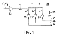
- the equalising circuits are selectively used by means of a branch circuit 21 shown in Figure 4 of the accompanying drawings.
- a reproduced output is applied to a transmission line, via an input buffer 22 and an input resistance R1, the transmission line including connection nodes a to c to which respective input selection switches 23, 24 and 25, each comprising an analogue switch, are respectively connected.
- the transmission line is terminated by one end of a terminating resistance R0 whose other end is connected to ground.
- the input selection switches 23, 24 and 25 are controlled to be selectively turned on so that record signals SA, SB and SC sent out from the output terminals of the switches 23, 24 or 25 are inputted to equalisers (not shown) which have equalising characteristics that are different from each other.
- a magnetic recording and reproducing apparatus comprising: a rotary head mounted on a drum on which a magnetic tape can be wound so as to reproduce an information signal recorded on the magnetic tape by helical scanning of the tape; a current amplification means for current amplifying a reproduced output obtained from the rotary head to produce a first reproduced signal, the current amplification means being disposed near the rotary head and inside of the drum; a lower band suppression means for suppressing a lower band component of the first reproduced signal to produce a second reproduced signal; a voltage amplification means for voltage amplifying the second reproduced signal to produce a third reproduced signal; a rotary transformer rotatable together with the rotary head, the transformer having a primary winding for receiving the third reproduced signal and a secondary winding for emitting the third reproduced signal; and a lower band emphasis means for compensating said lower band component suppression, effected by the lower band suppression means, in the third reproduced signal emitted by the rotary transformer, the lower band
- a preferred embodiment of the invention described in detail below provides a magnetic recording and reproducing apparatus in which reproduced outputs are commonly inputted to a plurality of equalising circuits connected in cascade without (or at least with reduced) distortion of amplitude caused by reflection.
- a plurality of equalising circuits (15A to 15F) is provided to effect predetermined signal processing.
- the equalising circuits (15A to 15F) are connected in cascade to have commonly inputted thereto a reproduced output (V12).
- the equalising circuits (15A to 15F) are so arranged that, in order of their proximity to a terminating resistance (R10), they process a reproduced output (V12) having a higher frequency.
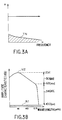
- FIGS 5A and 5B depict a data recording and reproducing apparatus 10 embodying the invention.
- a rotary head 2 disposed in the interior of a rotary drum reads (reproduces) the content of a magnetic tape 3.
- a head output current I1 obtained as a result of this is inputted to a preamplifier 6 disposed near the head 2 and inside of the drum.
- the preamplifier 6 which comprises a current type amplifier circuit, amplifies the head output current I1 and transmits the amplified current as a first reproduced output V2 to an emphasis circuit 11.
- the emphasis circuit 11 is constructed as an RC differentiating circuit including resistances R1, R2 and a capacitor C1.
- the emphasis circuit 11 sunpresses a low frequency component of the first reproduced output V2 and inputs it as a second reproduced output V10 to a driver 12A which comprises a voltage type amplifier circuit.
- the driver 12A amplifies the second reproduced output V10 inputted thereto and supplies it as a third reproduced output V11 to a primary winding of a rotary transformer 12B.
- the transformer 12B then transmits the output V11 to a de-emphasis circuit 12C disposed outside of the drum via a secondary winding thereof.
- the de-emphasis circuit 12C is constructed as an RC integrating circuit including resistances R3, R4 and a capacitor C2.
- the deemphasis circuit 12C emphasises a low frequency component of the third reproduced output V11 and transmits it as a fourth reproduced output V12 to a subsequent reproducing signal processing circuit.
- the de-emphasis circuit 12C has a characteristic such as to emphasise the low frequency component suppressed by the emphasis circuit 11, thereby compensating for the low frequency component suppression effected by the emphasis circuit 11.
- the preamplifier 6 amplifies the level of the head output current I1 sufficiently to obtain the first reproduced output V2.
- a low frequency component of the reproduced output which may cause a problem in terms of noise level in the driver 12A is suppressed sufficiently and then inputted to the driver 12A.
- the preamplifier 6 within the drum is capable of securing an adequate S/N ratio and dynamic range.
- the first reproduced output V2 obtained from the preamplifier 6, the magnetic conversion characteristic of the magnetic tape 3 and of the rotary head 2, noise TN corresponding to the preamplifier 6 and noise N1 of the driver 12A have, as explained above, frequency characteristics as shown in Figure 6A.
- the emphasis circuit 11, on the other hand is, as shown in Figure 6B, set to have a suppression characteristic EN such as to depress the low frequency component in which the recording wavelength is 18 micrometres or more by 12 dB.
- the second reproduced output V10 inputted to the driver 12A, as well as the noise TN contained in the second reproduced output V10, as shown in Figure 6C, exhibit frequency characteristics such that the low frequency component of the first reproduced output V2 and the low frequency component of the noise TN associated with the preamplifier 6 are suppressed.
- the noise level of the low frequency component which causes the problem in the driver 12A is thereby sufficiently suppressed.
- the de-emphasis circuit 12C is, as illustrated in Figure 6D, set to have an emphasis characteristic DE such as to raise the low frequency component having a recording wavelength of 18 micrometres or more by 12 dB with respect to the suppressed characteristic EN of the emphasis circuit 11.
- an emphasis characteristic DE such as to raise the low frequency component having a recording wavelength of 18 micrometres or more by 12 dB with respect to the suppressed characteristic EN of the emphasis circuit 11.
- a power source voltage and electric power after the rotary transformer 12B are thereby sufficiently secured.
- the frequency characteristic of the third reproduced output V11 reverts to the frequency characteristic of the original first reproduced output V2.
- the fourth reproduced input V12 is, as shown in Figure 5B, supplied to equalising circuits 15A to 15F via an input buffer circuit 13.
- the reproduced input V12 is supplied via the input buffer circuit 13 to one end of each of input selection switches 14A, 14B, 14C, 14E and 14F which comprise analogue switches and are connected to respective ones of a series of connection nodes a to f.
- the one node a forming a terminated end of the series of nodes is connected to ground via an input side terminating resistance R10.
- One of the input selection switches 14A to 14F is selectively on-controlled so that signals outputted from the other ends of the switches 14A to 14F are inputted to respective corresponding equalising circuits 15A, 15B, 15C, 15D, 15E and 15F.
- equalising circuits 15A to 15F can be arranged on a printed circuit board with the circuit patterns in the order of proximity described above.
- the components of the signal are respectively equalised in the equalising circuits having the maximum recording frequencies of 44 to 1.84 MHz and then supplied to an output buffer 17 via output selection switches 16A to 16F each comprising an analogue switch and one end of an outside terminating resistance R11 which is connected to ground at its other end.
- one of the output selection switches 16A to 16F is on-controlled so that a record signal S1 outputted from the output buffer 17 is equalised with an equalising characteristic corresponding to the maximum recording frequency of 44 to 1.84 MHz.
- equalising circuits 15A to 15F connected in cascade equalising circuits having equalising characteristics for such maximum recording frequencies that are of higher frequency in order of proximity to the terminating resistance R10 are connected. It is thus possible to realise a data recording and reproducing apparatus 10 in which induction of amplitude distortion by reflection is avoidable.
- the preamplifier 6 sufficiently amplifies the level of the head output current I1 so as thereby to obtain the first reproduced output V2.
- the low frequency component of the output V2 which may cause the above-mentioned problem in terms of the noise level in the driver 12A, is sufficiently suppressed and then inputted to the driver 12A.
- the power source voltage and electric power after the rotary transformer 12B can be sufficiently secured. In this state, the frequency characteristic reverts to its original characteristic. It is thus possible to attain a data recording and reproducing apparatus 10 in which the preamplifier 6 in the drum is capable of securing a sufficient S/N ratio and dynamic range.
- the emphasis circuit 11 and the de-emphasis circuit 12C in the above-discussed embodiment exhibit characteristics such as to depress and raise the low frequency component having the recording wavelength of 18 micrometres or more.
- the low frequency component is not limited to the recording wavelength of 18 micrometres or more, but may be set to a variety of values based on a consideration of noise characteristics.
- the same effects as those described above are attainable by setting a characteristic such as to raise the low frequency component in the de-emphasis circuit provided outwardly of the drum by a value depressed in the emphasis circuit provided inwardly of the drum.
- the invention is applied to a data recording and reproducing apparatus. But is not limited to this application.
- the invention is suitable more widely for application to any magnetic recording and reproducing apparatus such as, for example, a digital video tape recorder and a digital audio tape recorder for effecting recording and reproducing processes by helically scanning a magnetic tape with a rotary head mounted on a drum.
- the equalising circuits 15A to 15F having the equalising characteristics such that the maximum recording frequencies that are higher in order of proximity to the terminating resistance R10 are connected. It is thus possible to realise a data recording and reproducing apparatus 10 in which the induction of amplitude distortion by reflection is avoidable.
- the switches 14A to 14F and 16A to 16F interlocked with each other, are disposed at input stages and output stages of the equalising circuits 15A to 15F, respectively.
- this is not an essential feature of the invention.
- the invention may be embodied in such a manner that switches disposed at the input stage or the output stage only may be on-controlled.
- the present invention is also applicable to an equalising circuit of a recording signal processing circuit.
- the invention is applied to an equalising circuit of a data recording and reproducing apparatus
- the invention is more widely applicable to a frequency signal processing apparatus in which a frequency signal is commonly inputted to signal processing circuits which are cascade connected with each other and which comprise for example, a plurality of low pass filters, or a plurality of tuner means, or the like.
Landscapes
- Recording Or Reproducing By Magnetic Means (AREA)
- Digital Magnetic Recording (AREA)
Applications Claiming Priority (2)
| Application Number | Priority Date | Filing Date | Title |
|---|---|---|---|
| JP339767/90 | 1990-11-30 | ||
| JP2339767A JP2844922B2 (ja) | 1990-11-30 | 1990-11-30 | 磁気記録再生装置 |
Publications (3)
| Publication Number | Publication Date |
|---|---|
| EP0488811A2 true EP0488811A2 (fr) | 1992-06-03 |
| EP0488811A3 EP0488811A3 (en) | 1992-09-02 |
| EP0488811B1 EP0488811B1 (fr) | 1995-10-25 |
Family
ID=18330615
Family Applications (1)
| Application Number | Title | Priority Date | Filing Date |
|---|---|---|---|
| EP91311154A Expired - Lifetime EP0488811B1 (fr) | 1990-11-30 | 1991-11-29 | Appareil d'enregistrement et de reproduction magnétiques |
Country Status (5)
| Country | Link |
|---|---|
| US (1) | US5901005A (fr) |
| EP (1) | EP0488811B1 (fr) |
| JP (1) | JP2844922B2 (fr) |
| KR (1) | KR100220763B1 (fr) |
| DE (1) | DE69114108T2 (fr) |
Cited By (1)
| Publication number | Priority date | Publication date | Assignee | Title |
|---|---|---|---|---|
| EP0639827A1 (fr) * | 1993-08-19 | 1995-02-22 | Kabushiki Kaisha Toshiba | Appareil avec tête rotative |
Family Cites Families (5)
| Publication number | Priority date | Publication date | Assignee | Title |
|---|---|---|---|---|
| JPS57200926A (en) * | 1981-06-03 | 1982-12-09 | Hitachi Ltd | Signal processing circuit |
| JPS6012858U (ja) * | 1983-07-04 | 1985-01-28 | 日本ビクター株式会社 | ノイズリダクシヨン回路 |
| DE3715884A1 (de) * | 1986-05-14 | 1987-11-19 | Mitsumi Electric Co Ltd | Trommelanordnung zur halterung mehrerer rotierender aufzeichnungs- und wiedergabekoepfe |
| FR2628249B1 (fr) * | 1988-03-07 | 1994-06-24 | Schlumberger Ind Sa | Dispositif de couplage electrique rotatif pour enregistreur a tete tournante et enregistreur pourvu d'un tel dispositif |
| DE3811327A1 (de) * | 1988-04-02 | 1989-10-12 | Broadcast Television Syst | Schaltungsanordnung zum aufsprechen von signalen auf magnetband |
-
1990
- 1990-11-30 JP JP2339767A patent/JP2844922B2/ja not_active Expired - Fee Related
-
1991
- 1991-11-29 KR KR1019910021766A patent/KR100220763B1/ko not_active Expired - Fee Related
- 1991-11-29 EP EP91311154A patent/EP0488811B1/fr not_active Expired - Lifetime
- 1991-11-29 DE DE69114108T patent/DE69114108T2/de not_active Expired - Fee Related
-
1993
- 1993-09-28 US US08/128,053 patent/US5901005A/en not_active Expired - Fee Related
Cited By (2)
| Publication number | Priority date | Publication date | Assignee | Title |
|---|---|---|---|---|
| EP0639827A1 (fr) * | 1993-08-19 | 1995-02-22 | Kabushiki Kaisha Toshiba | Appareil avec tête rotative |
| US5682283A (en) * | 1993-08-19 | 1997-10-28 | Kabushiki Kaisha Toshiba | Rotary head apparatus having short distance between magnetic heads and rotary transformer |
Also Published As
| Publication number | Publication date |
|---|---|
| DE69114108T2 (de) | 1996-03-21 |
| EP0488811A3 (en) | 1992-09-02 |
| US5901005A (en) | 1999-05-04 |
| JPH04209303A (ja) | 1992-07-30 |
| DE69114108D1 (de) | 1995-11-30 |
| KR100220763B1 (ko) | 1999-10-01 |
| EP0488811B1 (fr) | 1995-10-25 |
| JP2844922B2 (ja) | 1999-01-13 |
Similar Documents
| Publication | Publication Date | Title |
|---|---|---|
| US4110798A (en) | Frequency response equalizer | |
| EP0385867A2 (fr) | Dispositif de reproduction d'un signal numérique | |
| EP0488811B1 (fr) | Appareil d'enregistrement et de reproduction magnétiques | |
| US5223990A (en) | Data recording apparatus | |
| EP0506055B1 (fr) | Dispositif d'accentuation | |
| KR100209886B1 (ko) | 디지탈 자기기록재생장치 | |
| EP0463885B1 (fr) | Circuit de déaccentuation non linéaire | |
| US5204790A (en) | Digital signal recording circuit for digital video cassette tape recorder | |
| KR940003663B1 (ko) | 디지탈 신호 재생회로 | |
| EP0430427A2 (fr) | Circuit égalisateur pour des signaux numériques | |
| EP0730271A1 (fr) | Méthode et appareil pour enregistrer des signaux numériques, milieu pour l'enregistrement de signaux numériques, et méthode et appareil pour transmettre des signaux numériques | |
| EP0147073A1 (fr) | Circuit de réduction du bruit pour un signal vidéo | |
| JPS607280A (ja) | 信号処理装置 | |
| NL8203618A (nl) | Inrichting voor het uitlezen van een registratiedrager. | |
| JP2644502B2 (ja) | 画像信号再生装置 | |
| JPH033161A (ja) | 回転ヘッド型磁気記録再生装置 | |
| JPH0432857Y2 (fr) | ||
| KR0159411B1 (ko) | 녹화 재생기의 저역 통과 필터 | |
| JP2508526B2 (ja) | 記録補償回路 | |
| JP2591356B2 (ja) | 記録再生装置 | |
| EP0453684A2 (fr) | Dispositif d'égalisation dans un enregistreur à bande magnétique pendant la phase de reproduction | |
| JPS63308492A (ja) | 記録再生装置の信号処理回路 | |
| JPH04111202A (ja) | 磁気記録装置 | |
| JPS60103720A (ja) | デイジタル信号読取装置 | |
| JPH05325406A (ja) | 情報信号の記録再生装置 |
Legal Events
| Date | Code | Title | Description |
|---|---|---|---|
| PUAI | Public reference made under article 153(3) epc to a published international application that has entered the european phase |
Free format text: ORIGINAL CODE: 0009012 |
|
| AK | Designated contracting states |
Kind code of ref document: A2 Designated state(s): DE FR GB |
|
| PUAL | Search report despatched |
Free format text: ORIGINAL CODE: 0009013 |
|
| AK | Designated contracting states |
Kind code of ref document: A3 Designated state(s): DE FR GB |
|
| 17P | Request for examination filed |
Effective date: 19930123 |
|
| 17Q | First examination report despatched |
Effective date: 19950112 |
|
| GRAA | (expected) grant |
Free format text: ORIGINAL CODE: 0009210 |
|
| AK | Designated contracting states |
Kind code of ref document: B1 Designated state(s): DE FR GB |
|
| REF | Corresponds to: |
Ref document number: 69114108 Country of ref document: DE Date of ref document: 19951130 |
|
| ET | Fr: translation filed | ||
| PLBE | No opposition filed within time limit |
Free format text: ORIGINAL CODE: 0009261 |
|
| STAA | Information on the status of an ep patent application or granted ep patent |
Free format text: STATUS: NO OPPOSITION FILED WITHIN TIME LIMIT |
|
| 26N | No opposition filed | ||
| PGFP | Annual fee paid to national office [announced via postgrant information from national office to epo] |
Ref country code: FR Payment date: 20011113 Year of fee payment: 11 |
|
| PGFP | Annual fee paid to national office [announced via postgrant information from national office to epo] |
Ref country code: GB Payment date: 20011128 Year of fee payment: 11 |
|
| PGFP | Annual fee paid to national office [announced via postgrant information from national office to epo] |
Ref country code: DE Payment date: 20011217 Year of fee payment: 11 |
|
| REG | Reference to a national code |
Ref country code: GB Ref legal event code: IF02 |
|
| PG25 | Lapsed in a contracting state [announced via postgrant information from national office to epo] |
Ref country code: GB Free format text: LAPSE BECAUSE OF NON-PAYMENT OF DUE FEES Effective date: 20021129 |
|
| PG25 | Lapsed in a contracting state [announced via postgrant information from national office to epo] |
Ref country code: DE Free format text: LAPSE BECAUSE OF NON-PAYMENT OF DUE FEES Effective date: 20030603 |
|
| GBPC | Gb: european patent ceased through non-payment of renewal fee | ||
| PG25 | Lapsed in a contracting state [announced via postgrant information from national office to epo] |
Ref country code: FR Free format text: LAPSE BECAUSE OF NON-PAYMENT OF DUE FEES Effective date: 20030731 |
|
| REG | Reference to a national code |
Ref country code: FR Ref legal event code: ST |