EP0488927A2 - Moteur à réducteur pour le relevage de stores et jalousies - Google Patents
Moteur à réducteur pour le relevage de stores et jalousies Download PDFInfo
- Publication number
- EP0488927A2 EP0488927A2 EP91500133A EP91500133A EP0488927A2 EP 0488927 A2 EP0488927 A2 EP 0488927A2 EP 91500133 A EP91500133 A EP 91500133A EP 91500133 A EP91500133 A EP 91500133A EP 0488927 A2 EP0488927 A2 EP 0488927A2
- Authority
- EP
- European Patent Office
- Prior art keywords
- unit
- outlet
- awnings
- blinds
- elevation
- Prior art date
- Legal status (The legal status is an assumption and is not a legal conclusion. Google has not performed a legal analysis and makes no representation as to the accuracy of the status listed.)
- Withdrawn
Links
Images
Classifications
-
- E—FIXED CONSTRUCTIONS
- E06—DOORS, WINDOWS, SHUTTERS, OR ROLLER BLINDS IN GENERAL; LADDERS
- E06B—FIXED OR MOVABLE CLOSURES FOR OPENINGS IN BUILDINGS, VEHICLES, FENCES OR LIKE ENCLOSURES IN GENERAL, e.g. DOORS, WINDOWS, BLINDS, GATES
- E06B9/00—Screening or protective devices for wall or similar openings, with or without operating or securing mechanisms; Closures of similar construction
- E06B9/56—Operating, guiding or securing devices or arrangements for roll-type closures; Spring drums; Tape drums; Counterweighting arrangements therefor
- E06B9/68—Operating devices or mechanisms, e.g. with electric drive
- E06B9/70—Operating devices or mechanisms, e.g. with electric drive comprising an electric motor positioned outside the roller
Definitions
- the present invention is about a reducing motor for the elevation of blinds and awnings, which has been designed to make up what, as a whole, could be said to be a more efficient and rational operating unit than the ones offered by other systems with a similar object.
- Blinds and awnings are usually elevated and lowered either using a tape which winds and unwinds around the blind or awning's axle, or using a lever which activates the corresponding device which acts upon that winding/unwinding axle or drum.
- These systems are clearly not very comfortable for the user, since they require a manual action to be kept up during all the process of raising and/or lowering the corresponding blind or awning.
- the object of the present invention is to solve all these problems using a solution based upon a simple, efficient and extremely versatile operating device.
- the above mentioned reducing motor or operating unit - which is the object of the present invention - includes an electric motor which transmits its rotation to the winding tube through a series of pinions, spiral conveyor and crown. It is attached to this tube by a bi-pyramidal-trunk element which allows both ends to be adjusted and attached, which, naturally, allows two axles or tubes - placed one in front of the other and belonging to two different systems of blinds or awnings, - to be attached to them.
- the operating unit includes a frame inside which all the necessary elements are installed, including the above mentioned electric motor which supplies the leading power required to move the elements attached to the operating unit in both directions.
- This motor's revolutions are reduced through a series of cylindrical, helicoidal and straight connections which, combined with a spiral conveyor and an outlet crown, provide an increase in the torque in that outlet, as well as a complete mechanical stability and firmness, preventing forces foreing to the operating unit from altering the unit's position.
- a programming disk is also included. This disk is designed to limit automatically the number of times the operating unit must turn in each direction.
- This programming disk is made up of two series of toothed disks linked to their corresponding micro-switches and hair springs for resetting, as well as two cams columns and a supporting plate for the unit.
- the programming disk memorizes the travel limits through some position activators made up by two control units placed on one of the sides of the operating unit, in such a manner that half a turn of each of these control units makes the programming disk memorize the travel limits; that is to say, both limit positions of the operating unit's exit axle are memorized.
- the electronic components are placed in a printed circuit, together with the micro-switches connections, the motor connection and the external supply line connection.
- the above described operating unit can be controlled by a combined double commutator switch that can be activated by the user.
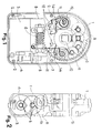
- Figure 1 shows a view of the device's reducing motor, without one of the two parts of the frame.
- Figure 2 shows a simplified view according to a cross section through a cut in the frame.
- the operating unit or the reducing motor itself is formed by an outer frame (1), made up of two symmetrical covers made of a light weight alloy, attached to each other by screws (2). In between these two covers there is a gastight seam situated in a perimetric cleavage - placed in the above mentioned covers for that purpose. All these elements conform a self-portable, gastight and robust unit.
- the electric motor (3) - small in size and with a high output - is placed inside the frame (1). It runs on DC, and has a high starting torque and a simple manoeuvre to change the direction of its operation, which offers various different connections depending on the power to be developed for each application.
- the outlet the above mentioned motor (3) has a pinion (4) which is a part of a series of cylindrical, helicoidal and straight connections (5).
- the said connections (4, 5) act as reduction pitches, with the first connection or pinion (4) with helicoidal tooth minimizing the amount of noise generated by the high revolutions of the motor (3), outlet, while the straight toothed connections (5) achieve a higher efficiency at a higher torque.
- the last pinion (4) or crown of these connections (5) is directly linked to a spiral conveyor (6), which is connected to an outlet crown (7).
- the unit also includes a programming disk and some position activators, as well as a printed circuit (8) for the electronic components and the control units of the operating unit itself.
- the programming disk includes a series of toothed disks (9), some micro-switches (10), hair springs (11) for resetting, two cams columns (12) and a support plate for the whole unit.
- the position activators are made up of two control units (13) which 180°C turn will memorize, in the programming disk, the position in which the outlet axle of the operating unit is at that moment, thus determining the ends of travel.
- micro-switches 10 (one for each direction) which cut the motor's (3) power supply.
- Each micro-switch (10) is equipped with a shiftable cams column (12), which, when in its resting position, rests on the micro-switch's (10) tongue (14), which means that they are on a conduction position.
- the operating unit can, therefore, work in both directions and with no end of travel when it is activated from the control unit.
- the outlet crown (7) has a concentric integral toothed wheel in one of its necks in such a way that, when it turns, so does the other toothed wheel placed on the side, since it is permanently connected to the crown's wheel.
- This wheel is common to the other two pairs of wheels (two in each cams column).
- the object of these two series of toothed wheels is to reduce the number of times the crown (7) turns, and to achieve only one revolution in the cams column (12), which establishes the system's maximun shift.
- the above mentioned columns (12) are equipped with a hair spring (11) which makes them rotate on their axle until they reach a stop placed in the column's lower, which is its resting position.
- a central toothed wheel, aligned with the micro-switch (10) has a slot in it which means that in its resting position the micro-switch is free, but not free enough to disconnect it electrically. Since the corresponding column (12) has shifted, the micro-switch's (10) tongue (14) is pressed down.
- the control unit In order to establish the first end of travel of the operating unit, the control unit must be activated in one of its directions, ad when the desired position is reached, the corresponding button (13) must be rotated half a turn.
- the stop position is now established, starting from this point, and the operating unit can only be activated in the opposite direction. When this happens, the column that has been previously adjusted will accumulate the number of turns that occur in the opposite direction, until it reaches the other desired limit.
- the position of the second column can be memorized by rotating the second button (13) at that moment.
- the operating unit's travel is comprised between the two pre-established limits, so that it will stop automatically in both directions when it reaches one of them.
- the unit includes a part (15) made up of two pyramidal trunk elements with square basis, which, when attched to the blind's or awning's transmitting tube, absorbs the bending or "deflection" caused by the weight.
Landscapes
- Engineering & Computer Science (AREA)
- Structural Engineering (AREA)
- Architecture (AREA)
- Civil Engineering (AREA)
- Blinds (AREA)
- Operating, Guiding And Securing Of Roll- Type Closing Members (AREA)
- Transmission Devices (AREA)
Applications Claiming Priority (2)
| Application Number | Priority Date | Filing Date | Title |
|---|---|---|---|
| ES9003041 | 1990-11-28 | ||
| ES9003041A ES2026811A6 (es) | 1990-11-28 | 1990-11-28 | Motor reductor para la elevacion de persianas y toldos. |
Publications (2)
| Publication Number | Publication Date |
|---|---|
| EP0488927A2 true EP0488927A2 (fr) | 1992-06-03 |
| EP0488927A3 EP0488927A3 (en) | 1992-06-24 |
Family
ID=8269825
Family Applications (1)
| Application Number | Title | Priority Date | Filing Date |
|---|---|---|---|
| EP19910500133 Withdrawn EP0488927A3 (en) | 1990-11-28 | 1991-11-27 | Reducing motor for the elevation of blinds and awnings |
Country Status (4)
| Country | Link |
|---|---|
| EP (1) | EP0488927A3 (fr) |
| CA (1) | CA2055967A1 (fr) |
| ES (1) | ES2026811A6 (fr) |
| PT (1) | PT99620A (fr) |
Cited By (4)
| Publication number | Priority date | Publication date | Assignee | Title |
|---|---|---|---|---|
| WO1998029635A3 (fr) * | 1996-12-27 | 1998-10-15 | Lutron Electronics Co | Systeme de store de fenetres motorise |
| WO2001069030A1 (fr) * | 2000-03-15 | 2001-09-20 | Viktor Alexeevich Evseenkov | Volets commandes |
| KR100417618B1 (ko) * | 2001-03-07 | 2004-02-05 | 주식회사 홈네스터 | 다중 롤 블라인드 장치 |
| KR100417619B1 (ko) * | 2001-05-30 | 2004-02-05 | 주식회사 홈네스터 | 다중 롤 블라인드 장치 |
Families Citing this family (1)
| Publication number | Priority date | Publication date | Assignee | Title |
|---|---|---|---|---|
| WO2000073615A1 (fr) * | 1999-05-28 | 2000-12-07 | Damalco Motor, S.L. | Actionneur perfectionne pour axe d'enroulement |
Family Cites Families (3)
| Publication number | Priority date | Publication date | Assignee | Title |
|---|---|---|---|---|
| DE2512102C3 (de) * | 1975-03-19 | 1979-01-18 | Siemens Ag, 1000 Berlin Und 8000 Muenchen | Abschalteinheit in einer Elektromotor-Antriebseinheit für Markisen und Rolladen |
| FR2377114A1 (fr) * | 1977-01-05 | 1978-08-04 | Franciaflex | Ensemble motoreducteur electrique a arret automatique de fin de course |
| DE3834643C2 (de) * | 1988-10-11 | 1995-11-30 | Berner Fa | Antriebseinheit |
-
1990
- 1990-11-28 ES ES9003041A patent/ES2026811A6/es not_active Expired - Lifetime
-
1991
- 1991-11-21 CA CA 2055967 patent/CA2055967A1/fr not_active Abandoned
- 1991-11-27 EP EP19910500133 patent/EP0488927A3/en not_active Withdrawn
- 1991-11-27 PT PT9962091A patent/PT99620A/pt not_active Application Discontinuation
Cited By (5)
| Publication number | Priority date | Publication date | Assignee | Title |
|---|---|---|---|---|
| WO1998029635A3 (fr) * | 1996-12-27 | 1998-10-15 | Lutron Electronics Co | Systeme de store de fenetres motorise |
| US5848634A (en) * | 1996-12-27 | 1998-12-15 | Latron Electronics Co. Inc. | Motorized window shade system |
| WO2001069030A1 (fr) * | 2000-03-15 | 2001-09-20 | Viktor Alexeevich Evseenkov | Volets commandes |
| KR100417618B1 (ko) * | 2001-03-07 | 2004-02-05 | 주식회사 홈네스터 | 다중 롤 블라인드 장치 |
| KR100417619B1 (ko) * | 2001-05-30 | 2004-02-05 | 주식회사 홈네스터 | 다중 롤 블라인드 장치 |
Also Published As
| Publication number | Publication date |
|---|---|
| ES2026811A6 (es) | 1992-05-01 |
| CA2055967A1 (fr) | 1992-05-29 |
| PT99620A (pt) | 1993-11-30 |
| EP0488927A3 (en) | 1992-06-24 |
Similar Documents
| Publication | Publication Date | Title |
|---|---|---|
| US10030442B2 (en) | Spring system for roller blinds | |
| EP0381643B1 (fr) | Dispositif pour la commande de rouleaux et de stores | |
| US4324386A (en) | Battens system for raising and lowering sceneries or similar loads on a stage | |
| US4392392A (en) | Electrically-operated roller door operating mechanism | |
| EP0488927A2 (fr) | Moteur à réducteur pour le relevage de stores et jalousies | |
| CN217705566U (zh) | 一种儿童安全座椅的电动旋转调节结构 | |
| CN115230544B (zh) | 一种儿童安全座椅的电动旋转躺角调节结构 | |
| EP0940553B1 (fr) | Dispositif d'actionnement pour un store à rouleau | |
| EP1118741A2 (fr) | Dispositif de transmission avec ensemble vis/écrou à contact de roulement et actionneur linéaire comprenant ce dispositif | |
| US20020062931A1 (en) | Method and apparatus for operating a blind | |
| CN111229987A (zh) | 一种加热圈绕制器 | |
| US20060243398A1 (en) | Device for rolling up/rolling down a shade | |
| CN219971454U (zh) | 一种电缆加工用绕线装置 | |
| GB2063358A (en) | Electrically-operated roller door mechanism | |
| CN217362834U (zh) | 一种百叶帘电机 | |
| CN117200665B (zh) | 跟随式光伏发电装置 | |
| EP0371170B1 (fr) | Dispositif enrouleur pour éléments enroulables tels que stores, volets roulants ou analogues | |
| TW277037B (fr) | ||
| CN217626845U (zh) | 一种用于钢索卷扬轮绕线的绕线装置 | |
| CN120487841A (zh) | 用于机械设备的差速锁锁止装置和机械设备 | |
| JP2000131765A5 (fr) | ||
| JPH053594U (ja) | 電動式シヤツターの開閉装置 | |
| JPH0974923A (ja) | ビニールハウスの巻き上げシート自動開閉装置 | |
| US866388A (en) | Spring-fan. | |
| NL9300087A (nl) | Elektrische zonneschermaandrijving met flexibele aandrijfas door buigzame askoker tussen de aandrijfmotor en de rechtstreeks op het handwindwerk te monteren aandrijfkop. |
Legal Events
| Date | Code | Title | Description |
|---|---|---|---|
| PUAI | Public reference made under article 153(3) epc to a published international application that has entered the european phase |
Free format text: ORIGINAL CODE: 0009012 |
|
| PUAL | Search report despatched |
Free format text: ORIGINAL CODE: 0009013 |
|
| AK | Designated contracting states |
Kind code of ref document: A2 Designated state(s): AT BE CH DE DK FR GB GR IT LI LU NL SE |
|
| AK | Designated contracting states |
Kind code of ref document: A3 Designated state(s): AT BE CH DE DK FR GB GR IT LI LU NL SE |
|
| 17P | Request for examination filed |
Effective date: 19921223 |
|
| STAA | Information on the status of an ep patent application or granted ep patent |
Free format text: STATUS: THE APPLICATION IS DEEMED TO BE WITHDRAWN |
|
| 18D | Application deemed to be withdrawn |
Effective date: 19960601 |