EP0488947A1 - Cellule détectrice - Google Patents
Cellule détectrice Download PDFInfo
- Publication number
- EP0488947A1 EP0488947A1 EP91810895A EP91810895A EP0488947A1 EP 0488947 A1 EP0488947 A1 EP 0488947A1 EP 91810895 A EP91810895 A EP 91810895A EP 91810895 A EP91810895 A EP 91810895A EP 0488947 A1 EP0488947 A1 EP 0488947A1
- Authority
- EP
- European Patent Office
- Prior art keywords
- approximately
- detector cell
- cell according
- cover part
- openings
- Prior art date
- Legal status (The legal status is an assumption and is not a legal conclusion. Google has not performed a legal analysis and makes no representation as to the accuracy of the status listed.)
- Granted
Links
- 230000003993 interaction Effects 0.000 claims abstract description 20
- 238000005259 measurement Methods 0.000 claims abstract description 20
- 230000003287 optical effect Effects 0.000 claims abstract description 4
- 238000003780 insertion Methods 0.000 claims description 16
- 230000037431 insertion Effects 0.000 claims description 16
- 239000013307 optical fiber Substances 0.000 claims description 13
- 238000010521 absorption reaction Methods 0.000 claims description 9
- 238000000034 method Methods 0.000 claims description 9
- 230000005855 radiation Effects 0.000 claims description 9
- 239000000463 material Substances 0.000 claims description 8
- 239000003153 chemical reaction reagent Substances 0.000 claims description 6
- 229910021419 crystalline silicon Inorganic materials 0.000 claims description 5
- 235000012431 wafers Nutrition 0.000 claims description 3
- 150000001875 compounds Chemical class 0.000 claims description 2
- 239000004020 conductor Substances 0.000 claims description 2
- 238000005530 etching Methods 0.000 claims description 2
- 239000000835 fiber Substances 0.000 claims description 2
- 239000007788 liquid Substances 0.000 claims description 2
- 230000000737 periodic effect Effects 0.000 claims description 2
- 239000013078 crystal Substances 0.000 claims 1
- 230000000873 masking effect Effects 0.000 claims 1
- 238000013461 design Methods 0.000 abstract description 5
- 229910052710 silicon Inorganic materials 0.000 abstract description 5
- 239000010703 silicon Substances 0.000 abstract description 5
- 239000010453 quartz Substances 0.000 abstract description 2
- VYPSYNLAJGMNEJ-UHFFFAOYSA-N silicon dioxide Inorganic materials O=[Si]=O VYPSYNLAJGMNEJ-UHFFFAOYSA-N 0.000 abstract description 2
- 238000000926 separation method Methods 0.000 description 10
- 230000009102 absorption Effects 0.000 description 8
- 238000001514 detection method Methods 0.000 description 7
- 238000004811 liquid chromatography Methods 0.000 description 7
- 238000004519 manufacturing process Methods 0.000 description 7
- 238000005251 capillar electrophoresis Methods 0.000 description 6
- 238000004401 flow injection analysis Methods 0.000 description 5
- XUIMIQQOPSSXEZ-UHFFFAOYSA-N Silicon Chemical compound [Si] XUIMIQQOPSSXEZ-UHFFFAOYSA-N 0.000 description 4
- 238000005516 engineering process Methods 0.000 description 3
- 229910021421 monocrystalline silicon Inorganic materials 0.000 description 3
- 230000008569 process Effects 0.000 description 3
- 238000012545 processing Methods 0.000 description 3
- 238000004808 supercritical fluid chromatography Methods 0.000 description 3
- 238000004458 analytical method Methods 0.000 description 2
- 230000000694 effects Effects 0.000 description 2
- 230000003647 oxidation Effects 0.000 description 2
- 238000007254 oxidation reaction Methods 0.000 description 2
- 238000003672 processing method Methods 0.000 description 2
- 239000004065 semiconductor Substances 0.000 description 2
- 238000001228 spectrum Methods 0.000 description 2
- 239000000126 substance Substances 0.000 description 2
- 229910004298 SiO 2 Inorganic materials 0.000 description 1
- 229910021417 amorphous silicon Inorganic materials 0.000 description 1
- 230000005540 biological transmission Effects 0.000 description 1
- 230000015572 biosynthetic process Effects 0.000 description 1
- 239000011248 coating agent Substances 0.000 description 1
- 238000000576 coating method Methods 0.000 description 1
- 230000001427 coherent effect Effects 0.000 description 1
- 239000002131 composite material Substances 0.000 description 1
- 238000010276 construction Methods 0.000 description 1
- 230000001419 dependent effect Effects 0.000 description 1
- 238000011161 development Methods 0.000 description 1
- 230000005684 electric field Effects 0.000 description 1
- 238000003891 environmental analysis Methods 0.000 description 1
- 230000010354 integration Effects 0.000 description 1
- 239000000203 mixture Substances 0.000 description 1
- 230000002572 peristaltic effect Effects 0.000 description 1
- 238000001020 plasma etching Methods 0.000 description 1
- 230000035939 shock Effects 0.000 description 1
- 150000003377 silicon compounds Chemical class 0.000 description 1
- 230000007480 spreading Effects 0.000 description 1
- 230000007704 transition Effects 0.000 description 1
- 238000003631 wet chemical etching Methods 0.000 description 1
Images



Classifications
-
- G—PHYSICS
- G01—MEASURING; TESTING
- G01N—INVESTIGATING OR ANALYSING MATERIALS BY DETERMINING THEIR CHEMICAL OR PHYSICAL PROPERTIES
- G01N27/00—Investigating or analysing materials by the use of electric, electrochemical, or magnetic means
- G01N27/26—Investigating or analysing materials by the use of electric, electrochemical, or magnetic means by investigating electrochemical variables; by using electrolysis or electrophoresis
- G01N27/416—Systems
- G01N27/447—Systems using electrophoresis
- G01N27/44704—Details; Accessories
- G01N27/44717—Arrangements for investigating the separated zones, e.g. localising zones
- G01N27/44721—Arrangements for investigating the separated zones, e.g. localising zones by optical means
-
- B—PERFORMING OPERATIONS; TRANSPORTING
- B01—PHYSICAL OR CHEMICAL PROCESSES OR APPARATUS IN GENERAL
- B01L—CHEMICAL OR PHYSICAL LABORATORY APPARATUS FOR GENERAL USE
- B01L3/00—Containers or dishes for laboratory use, e.g. laboratory glassware; Droppers
- B01L3/50—Containers for the purpose of retaining a material to be analysed, e.g. test tubes
- B01L3/502—Containers for the purpose of retaining a material to be analysed, e.g. test tubes with fluid transport, e.g. in multi-compartment structures
- B01L3/5027—Containers for the purpose of retaining a material to be analysed, e.g. test tubes with fluid transport, e.g. in multi-compartment structures by integrated microfluidic structures, i.e. dimensions of channels and chambers are such that surface tension forces are important, e.g. lab-on-a-chip
- B01L3/502715—Containers for the purpose of retaining a material to be analysed, e.g. test tubes with fluid transport, e.g. in multi-compartment structures by integrated microfluidic structures, i.e. dimensions of channels and chambers are such that surface tension forces are important, e.g. lab-on-a-chip characterised by interfacing components, e.g. fluidic, electrical, optical or mechanical interfaces
-
- G—PHYSICS
- G01—MEASURING; TESTING
- G01N—INVESTIGATING OR ANALYSING MATERIALS BY DETERMINING THEIR CHEMICAL OR PHYSICAL PROPERTIES
- G01N21/00—Investigating or analysing materials by the use of optical means, i.e. using sub-millimetre waves, infrared, visible or ultraviolet light
- G01N21/01—Arrangements or apparatus for facilitating the optical investigation
- G01N21/03—Cuvette constructions
- G01N21/05—Flow-through cuvettes
-
- B—PERFORMING OPERATIONS; TRANSPORTING
- B01—PHYSICAL OR CHEMICAL PROCESSES OR APPARATUS IN GENERAL
- B01L—CHEMICAL OR PHYSICAL LABORATORY APPARATUS FOR GENERAL USE
- B01L2300/00—Additional constructional details
- B01L2300/06—Auxiliary integrated devices, integrated components
- B01L2300/0627—Sensor or part of a sensor is integrated
- B01L2300/0654—Lenses; Optical fibres
-
- B—PERFORMING OPERATIONS; TRANSPORTING
- B01—PHYSICAL OR CHEMICAL PROCESSES OR APPARATUS IN GENERAL
- B01L—CHEMICAL OR PHYSICAL LABORATORY APPARATUS FOR GENERAL USE
- B01L2300/00—Additional constructional details
- B01L2300/08—Geometry, shape and general structure
- B01L2300/0861—Configuration of multiple channels and/or chambers in a single devices
- B01L2300/0877—Flow chambers
-
- B—PERFORMING OPERATIONS; TRANSPORTING
- B01—PHYSICAL OR CHEMICAL PROCESSES OR APPARATUS IN GENERAL
- B01L—CHEMICAL OR PHYSICAL LABORATORY APPARATUS FOR GENERAL USE
- B01L2300/00—Additional constructional details
- B01L2300/16—Surface properties and coatings
- B01L2300/168—Specific optical properties, e.g. reflective coatings
-
- B—PERFORMING OPERATIONS; TRANSPORTING
- B01—PHYSICAL OR CHEMICAL PROCESSES OR APPARATUS IN GENERAL
- B01L—CHEMICAL OR PHYSICAL LABORATORY APPARATUS FOR GENERAL USE
- B01L2400/00—Moving or stopping fluids
- B01L2400/04—Moving fluids with specific forces or mechanical means
- B01L2400/0475—Moving fluids with specific forces or mechanical means specific mechanical means and fluid pressure
- B01L2400/0487—Moving fluids with specific forces or mechanical means specific mechanical means and fluid pressure fluid pressure, pneumatics
-
- G—PHYSICS
- G01—MEASURING; TESTING
- G01N—INVESTIGATING OR ANALYSING MATERIALS BY DETERMINING THEIR CHEMICAL OR PHYSICAL PROPERTIES
- G01N21/00—Investigating or analysing materials by the use of optical means, i.e. using sub-millimetre waves, infrared, visible or ultraviolet light
- G01N21/01—Arrangements or apparatus for facilitating the optical investigation
- G01N21/03—Cuvette constructions
- G01N2021/0346—Capillary cells; Microcells
-
- G—PHYSICS
- G01—MEASURING; TESTING
- G01N—INVESTIGATING OR ANALYSING MATERIALS BY DETERMINING THEIR CHEMICAL OR PHYSICAL PROPERTIES
- G01N21/00—Investigating or analysing materials by the use of optical means, i.e. using sub-millimetre waves, infrared, visible or ultraviolet light
- G01N21/01—Arrangements or apparatus for facilitating the optical investigation
- G01N21/03—Cuvette constructions
- G01N21/05—Flow-through cuvettes
- G01N2021/052—Tubular type; cavity type; multireflective
-
- G—PHYSICS
- G01—MEASURING; TESTING
- G01N—INVESTIGATING OR ANALYSING MATERIALS BY DETERMINING THEIR CHEMICAL OR PHYSICAL PROPERTIES
- G01N30/00—Investigating or analysing materials by separation into components using adsorption, absorption or similar phenomena or using ion-exchange, e.g. chromatography or field flow fractionation
- G01N30/02—Column chromatography
- G01N30/62—Detectors specially adapted therefor
- G01N30/74—Optical detectors
- G01N2030/746—Optical detectors detecting along the line of flow, e.g. axial
-
- G—PHYSICS
- G01—MEASURING; TESTING
- G01N—INVESTIGATING OR ANALYSING MATERIALS BY DETERMINING THEIR CHEMICAL OR PHYSICAL PROPERTIES
- G01N35/00—Automatic analysis not limited to methods or materials provided for in any single one of groups G01N1/00 - G01N33/00; Handling materials therefor
- G01N2035/00178—Special arrangements of analysers
- G01N2035/00237—Handling microquantities of analyte, e.g. microvalves, capillary networks
-
- G—PHYSICS
- G01—MEASURING; TESTING
- G01N—INVESTIGATING OR ANALYSING MATERIALS BY DETERMINING THEIR CHEMICAL OR PHYSICAL PROPERTIES
- G01N27/00—Investigating or analysing materials by the use of electric, electrochemical, or magnetic means
- G01N27/26—Investigating or analysing materials by the use of electric, electrochemical, or magnetic means by investigating electrochemical variables; by using electrolysis or electrophoresis
- G01N27/416—Systems
- G01N27/447—Systems using electrophoresis
-
- G—PHYSICS
- G01—MEASURING; TESTING
- G01N—INVESTIGATING OR ANALYSING MATERIALS BY DETERMINING THEIR CHEMICAL OR PHYSICAL PROPERTIES
- G01N30/00—Investigating or analysing materials by separation into components using adsorption, absorption or similar phenomena or using ion-exchange, e.g. chromatography or field flow fractionation
- G01N30/02—Column chromatography
- G01N30/60—Construction of the column
- G01N30/6095—Micromachined or nanomachined, e.g. micro- or nanosize
-
- G—PHYSICS
- G01—MEASURING; TESTING
- G01N—INVESTIGATING OR ANALYSING MATERIALS BY DETERMINING THEIR CHEMICAL OR PHYSICAL PROPERTIES
- G01N30/00—Investigating or analysing materials by separation into components using adsorption, absorption or similar phenomena or using ion-exchange, e.g. chromatography or field flow fractionation
- G01N30/02—Column chromatography
- G01N30/62—Detectors specially adapted therefor
- G01N30/74—Optical detectors
Definitions
- the invention relates to a detector cell, in particular for measuring the absorption of ultraviolet and / or visible radiation according to the preamble of patent claim 1.
- Detector cells for measuring the absorption of a sample in the ultraviolet (UV) and / or visible range of the electromagnetic spectrum are used in large numbers in analytical chemistry. If necessary, measurements of excited fluorescence, chemiluminescence or absorption in the infrared (IR) range of the spectrum are also carried out.
- detector cells for absorption measurements are used in particular for analytical separation methods such as liquid chromatography (liquid chromatography LC), capillary electrophoresis (capillary electrophoresis CE), supercritical fluid chromatography (SFC) or Flow injection analysis (FIA) is increasingly being used.
- Such detector cells are usually designed as flow cells.
- measuring cells are described for example in US-A-3,810,695 or also in US-A-4,243,883. They are intended for on-line use in production plants and the like and have relatively large volumes of the measuring chamber. However, these flow cells are not suitable for use in analytical separation methods because the large volumes of the measuring chamber would result in renewed mixing and uncontrollable widening of the separated sample components in the carrier medium
- flow-through cells These essentially represent a downsizing of the known flow cells.
- Such cuvettes usually have measuring volumes of a few hundreds of nanoliters to a few milliliters. Measuring cells of this type are described, for example, in a publication by Edward S. Yeung and Robert E. Synovec in Analytical Chemistry, Vol. 58, No. 12, October 1986, pages 1237A-1256A.
- a suitable design of the flow area - approximately Z-shaped in the exemplary embodiment described - and an approximately oblique irradiation of the sample in the measuring cell area mean that the measuring beam travels as long as possible in the sample in order to achieve the greatest possible probability of absorption.
- detector cells designed in this way do not lead to the desired results with the desired resolution and accuracy.
- the so-called "on-column" detectors represent an alternative type of detector cells.
- a piece of a capillary or the capillary of the named analysis system itself is used as a limitation of the measurement volume.
- Such a measuring cell is described, for example, in EP-A-0,326,511.
- This comprises a capillary which is fixed in a two-part holder. The measuring light is radiated through openings provided in the holder perpendicular to the capillary axis and the transmitted portion of the measuring light on the opposite side of the capillary is collected and detected again.
- the measuring light of a measuring light source arranged outside the measuring cell is led to the capillary via optical fiber and also removed again in this way.
- the usual spectroscopic light sources but also coherent light source lasers are used as measurement light sources.
- the detection limit (defined as the smallest measurable concentration of the eluted sample molecule) is due to the small interaction distance, which essentially corresponds to the inside diameter of the capillary used corresponds, set limits.
- the inside diameters of the capillaries are about 10 ⁇ m to 50 ⁇ m.
- the measuring light is proposed by Xiaobing Xi and Edward S. Yeung in Analytical Chemistry, 1990, 62, pages 1580-1585 or also in EP-A-0,089,157 Guide the laser source through the capillary in the direction of flow. In this way, the interaction path length is extended by up to a factor of 1000 compared to the method in which the light is irradiated perpendicular to the capillary axis.
- the measurement light is not only weakened by absorption of the sample when it passes through the relatively long capillary, but there are scattering processes in the capillary; parts of the measurement light are often also absorbed by the capillary wall and the measurement result is thus falsified.
- the volume of the measuring chamber of the detection cell should be less than 10 ⁇ l in order to avoid undesired spreading and renewed mixing of the separated substances, it is clear that the transition to capillary diameters of 10 ⁇ m or less the volume of the measuring chamber of the detector cell should be in the range of about 1 nl or less.
- the detector cell should be easy to use and, in particular, should also be usable in miniaturized separators. In addition to being as compact as possible, the detector cell should be as simple, reproducible and inexpensive to manufacture as possible.
- the measuring chamber of the detector cell should not absorb the measuring light.
- the length of the interaction path of the measuring light with the sample - the optical path length - should be reproducible. There is also a desire for a small detector cell that allows a continuous measurement process.
- An analytical system shown for example in FIG. 1 for use in liquid chromatography (LC), capillary electrophoresis (CE), supercritical liquid chromatography (SFC) or flow injection analysis (FIA) is provided overall with the reference number 1. It essentially comprises a flow injection analysis and / or separation station 2 and a detection system 3.
- the flow injection analysis and / or separation station 2 and the detection system 3 can, as shown, be two separate structural units that are connected to lines 24, they can of course also be combined into a single device.
- the detection system 3 also contains a detector cell 4 according to the invention.
- the detector cell 4 is preferably constructed in two parts.
- Feed lines 14, 15, preferably capillaries, for the sample and any other reagents and the like, as well as a discharge line 16 for the sample or the sample-reagent mixture open into connection openings in the cover part 5.
- Two Optical fibers 12, 13 open into connection openings provided for this purpose in the cover part 5 and serve to feed and discharge the measuring light.
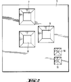
- connection openings 7, 8 and 9 for the capillaries 14, 15, 16, through which the sample and possibly further reagents are introduced into or removed from the detector cell 4 are clearly recognizable.
- the connection openings 7, 8, 9 are preferably designed as insertion openings in such a way that an inserted capillary 14, 15 or 16 is stuck without additional fixing means.
- the capillaries preferably have a transmission diameter of approximately 50 ⁇ m to approximately 1000 ⁇ m.
- the cross section of the insertion openings 7, 8, 9 can taper downward as shown above the height of the cover part 5, so that, as shown in the top view in FIG. 2, the openings have a truncated pyramid shape.
- the shape of the truncated cone is the same.
- the smallest cross section of the insertion openings 7, 8, 9 should correspond approximately to the inner cross section of the capillaries 14, 15, 16 used.
- the insertion openings 10 and 11 for the optical fibers 12 and 13 are formed analogously, but they usually have a smaller cross section.
- the opening cross section tapering from top to bottom over the height of the cover part 5 is clearly visible.
- the smallest cross section should also correspond approximately to the cross section of the light-conducting core of the fiber in the insertion openings 10, 11 for the optical fiber conductors 12, 13.
- the insertion openings 7, 8, 9, 10, 11 can, however, also be designed in a step-like manner or have a constant diameter.
- the associated base part 6 shown in FIG. 3 has a series of channels which are interconnected.
- two feed channels 17 and 18 are connected to the connection openings 7 and 8 for the capillaries 14 and 15 and open into a channel piece 20.
- a further channel 19 can open into the channel piece 20 as shown and on the base part 6 form a direct connection of the system from the outside to the outside.
- the channel section 20 opens into a channel section 21, which represents the interaction path to be explained in more detail.
- there is also a duct piece 22 which, when the detector cell 4 is assembled, is connected to the insertion opening 9 for the discharge capillary 16. 3, the feed channels 17 and 18 have larger dimensions than the channel system 20-21-22.
- the feed channels 17 and 18 provide a kind of reservoir for the sample that is usually pumped through the detector cell 4 with the aid of peristaltic pumps or for additional samples
- the smaller cross section of the channel system 20-21-22 builds up a low pressure in the feed channels 17, 18, which ensures a continuous transport of the media through the detector cell 4 even with slightly fluctuating pump outputs.
- This buffer function of the feed channels 17, 18 with a larger cross section also largely absorbs shock waves that arise in the transported media due to the movement of pistons or diaphragms of the pumps.
- the channel 19 leading to the outside has the same cross-section as the channel system 20-21-22. It is used, for example, to feed the sample when such effects are irrelevant or do not occur at all due to different transport methods for the sample, for example with the aid of electric fields.
- FIG. 4 shows a sectional view of the channel section 21 according to section line IV-IV in FIG. 3.
- this channel section which forms the actual interaction area for the measurement light R with the sample to be examined, is shown in the assembled state of the detector cell 4.
- the preferably straight channel piece 21 is connected at both ends to the insertion openings 10 and 11 for the two optical fibers 12 and 13.
- the already mentioned shape of the insertion openings 10 and 11, which tapers in cross-section from top to bottom over the height of the cover part 5, is also clearly visible. Two inserted optical fibers 12 and 13 are indicated.
- the design of the channel section 21, the actual interaction area, is such that the end side walls 25 of the channel section 21 form an angle ⁇ of approximately 90 ° to approximately 180 °, in particular approximately 110 ° to approximately 150 °, with the bottom 26 of the channel section 21 .
- the longitudinal side walls of the channel piece 21 are usually also inclined at a similar angle to the channel floor.
- the underside of the cover part 5, that is the side which faces the channel bottom 26, is coated with a reflection layer 23 at least in the region of the channel section 21 serving as an interaction region.
- the front side walls 25 of the channel piece 21 and the channel bottom 26 also have well reflecting surfaces. This can also be achieved by a suitable coating. However, a very well reflective material can also be used for the production of the base part 6.
- the volume of the upper part limited by the coated underside of the cover part 5 Channel piece 21 is preferably about 25 fl to about 1 ul. With a channel depth of approximately 0.5 ⁇ m to approximately 500 ⁇ m, this results in a channel cross-sectional area of the channel piece 21 of approximately 0.25 ⁇ m2 to approximately 0.25 mm2.
- Measuring light R which is radiated through the optical fiber 12 inserted into the connection opening 10, strikes the inclined front side wall 25 of the channel piece 21 on the input side and is reflected from there to the channel floor 26. According to the laws of reflection, the measurement light R is reflected from the channel floor 26 to the reflection layer 23 on the underside of the cover part 5, from there back to the channel floor 26, etc.
- the measurement light R reaches the second front side wall 25 of the channel piece 21 and is directed from there of the connection opening 11 is reflected and coupled into the inserted optical fiber 13 and conducted away. Due to these multiple reflections, the interaction distance of the measuring light R is significantly extended, in particular one obtains in this way with lengths of the channel section from approximately 100 ⁇ m to approximately 5 cm and with a channel depth of approximately 0.5 ⁇ m to approximately 500 ⁇ m interaction distances, i.e. optical lengths , from about 0.1 mm to about 10 cm.
- the detector cell 4 In the application of the detector cell 4, one sample and possibly further ones are used. Reagents introduced into the detector cell 4 via the connection openings 7, 8, 9 or 19. A preliminary run ensures that the detector cell is filled.
- the optical fibers 12 and 13 can be varied in the funnel-shaped insertion openings 10 and 11 with respect to the relative position of their light entry or light exit ends to the input and output side end walls 25 of the channel piece 21 and in this way the refraction effects of the liquid sample can be compensated for.
- the angle of incidence of the measurement light R is varied in this way until a maximum signal level is reached.
- this "calibration" can also be carried out by changing the position of the light exit optical fiber 13, or else by changing the position of the two optical fibers 12 and 13. After these preparatory measures, the actual absorption measurement can take place.
- the cover part 5 and the base part 6 are preferably produced from single-crystal silicon.
- the choice of this material allows the use of proven manufacturing techniques, such as those known from the semiconductor industry.
- the individual channels can be created photolithographically, by using mask technologies and, for example, wet chemical or plasma etching steps.
- the use of these technologies, which are known from semiconductor production, enables the reproducible production of a large number of identical ones Components.
- the mirroring of the surfaces of the channels, or at least of the channel section 21 serving as the interaction region, takes place by oxidation of the single-crystal silicon with the formation of a precisely adjustable thickness of an SiO 2 layer.
- the underside of the cover part can also be provided with a reflective layer simply by oxidation.
- connection openings 7-11 are likewise produced in a photolithographic manner by etching very specific areas of the single-crystalline silicon. Of course, these openings could also be drilled using a laser. It goes without saying that not only single-crystal silicon can be considered as materials for the production of the detector cell 4. Of course, materials similar to silicon from the IV main group of the Periodic Table of the Elements and so-called III-V connecting materials can also be used. Quartz or polycrystalline materials and even amorphous silicon compounds and compounds similar to them can also be used. Instead of the photolithographic processing methods for creating the insertion openings in the cover part and the channels in the base part, these could also be produced using micromechanical processing methods.
- Single crystalline silicon is supplied in slices up to 8 inches in diameter. If one takes into account that the dimensions of the detector cell 4 according to the invention provide a length of approximately 3 mm to approximately 55 mm and a width of only approximately 3 mm to approximately 10 mm, it is easy to see that in this way a single-crystalline silicon can be found on a wafer alone A large number of identical components can be produced in a very cost-effective manner. The finished components (cover parts or base parts) only have to be sawed out of the pane.
- the thickness of silicon wafers is usually about 50 microns to about 1000 microns.
- this thickness determines the height of an individual component, cover part or base part, this results in composite detector cells after processing and separation, which have a construction height of only approximately 150 ⁇ m to approximately 2000 ⁇ m.
- the cover part 5 and the base part 6 of the detector cell 4 are usually glued to one another or otherwise permanently connected. However, they could also be pressed together in a common holder.
- the design of the detector cell according to the invention has a sufficiently small measuring chamber volume (volume of the interaction area) without the detection limit being deteriorated in comparison with the known, conventional cells. Due to the miniaturized design, the detector cell according to the invention also fulfills the requirement for Integration into miniaturized analysis systems, such as those used in modern capillary and micro separation techniques of today or in the future.
Landscapes
- Health & Medical Sciences (AREA)
- Chemical & Material Sciences (AREA)
- Life Sciences & Earth Sciences (AREA)
- General Health & Medical Sciences (AREA)
- Analytical Chemistry (AREA)
- Immunology (AREA)
- Biochemistry (AREA)
- General Physics & Mathematics (AREA)
- Physics & Mathematics (AREA)
- Pathology (AREA)
- Molecular Biology (AREA)
- Chemical Kinetics & Catalysis (AREA)
- Electrochemistry (AREA)
- Dispersion Chemistry (AREA)
- Hematology (AREA)
- Clinical Laboratory Science (AREA)
- Optical Measuring Cells (AREA)
- Investigating Or Analysing Materials By Optical Means (AREA)
Applications Claiming Priority (2)
| Application Number | Priority Date | Filing Date | Title |
|---|---|---|---|
| CH374190 | 1990-11-26 | ||
| CH3741/90 | 1990-11-26 |
Publications (2)
| Publication Number | Publication Date |
|---|---|
| EP0488947A1 true EP0488947A1 (fr) | 1992-06-03 |
| EP0488947B1 EP0488947B1 (fr) | 1995-02-15 |
Family
ID=4262503
Family Applications (1)
| Application Number | Title | Priority Date | Filing Date |
|---|---|---|---|
| EP91810895A Expired - Lifetime EP0488947B1 (fr) | 1990-11-26 | 1991-11-18 | Cellule détectrice |
Country Status (4)
| Country | Link |
|---|---|
| US (1) | US5599503A (fr) |
| EP (1) | EP0488947B1 (fr) |
| JP (1) | JPH04268437A (fr) |
| DE (1) | DE59104604D1 (fr) |
Cited By (24)
| Publication number | Priority date | Publication date | Assignee | Title |
|---|---|---|---|---|
| JPH0634544A (ja) * | 1992-07-13 | 1994-02-08 | Mitsubishi Materials Corp | 赤外線式ガスセンサ |
| JPH0634543A (ja) * | 1992-07-13 | 1994-02-08 | Mitsubishi Materials Corp | 赤外線式ガスセンサ |
| WO1995001559A3 (fr) * | 1993-07-02 | 1995-02-16 | Evotec Biosystems Gmbh | Porte-echantillons et son utilisation |
| WO1997001087A1 (fr) * | 1995-06-23 | 1997-01-09 | Novartis Ag | Cuve de circulation |
| EP0762119A1 (fr) * | 1995-09-06 | 1997-03-12 | Hewlett-Packard GmbH | Dispositif photométriques pour des échantillons à volume faible |
| DE19648695A1 (de) * | 1996-11-25 | 1997-06-19 | Vermes Mikrotechnik Gmbh | Vorrichtung zur automatischen und kontinuierlichen Analyse von Flüssigkeitsproben |
| EP0789238A1 (fr) * | 1996-02-07 | 1997-08-13 | Chrompack International B.V. | Dispositif d'interface exchangeable entre des composants de système chromatographique et des chromatographes miniaturisés en phase gazeuse |
| EP0790496A1 (fr) * | 1996-02-15 | 1997-08-20 | Shimadzu Corporation | Cellule à échantillon liquide pour un appareil de mesure optique |
| EP0823054A1 (fr) * | 1995-04-27 | 1998-02-11 | Pharmacia Biotech AB | Appareil de mesure en continu de parametres physiques et chimiques dans un ecoulement de fluide |
| DE19647644A1 (de) * | 1996-11-18 | 1998-05-20 | Fraunhofer Ges Forschung | Mikromechanische Transmissionsmeßzelle |
| WO1998022803A1 (fr) * | 1996-11-18 | 1998-05-28 | Fraunhofer-Gesellschaft zur Förderung der angewandten Forschung e.V. | Cellule micromecanique de mesure de transmission |
| EP0808456A4 (fr) * | 1994-11-10 | 1998-09-02 | Sarnoff Corp | Ensemble compartimente de dispositifs electroniques |
| DE19738626A1 (de) * | 1997-09-04 | 1999-03-11 | Erhard Wendlandt | Verfahren mit Vorrichtungen zur Identifizierung und Charakterisierung von mikrobiologischen Individuen - nebst ihrer Kultivierung - sowie Partikeln im Mikrometer-/Nanometerbereich mit Hilfe von Mikrodurchfluß- und Kulturküvetten |
| DE10216047A1 (de) * | 2002-04-11 | 2003-10-23 | Univ Albert Ludwigs Freiburg | Monolithische Multi-Pass-Zelle |
| WO2003068671A3 (fr) * | 2002-02-16 | 2003-12-24 | Micronas Gmbh | Procede de production d'un systeme de detecteur et d'actionneur et systeme de detecteur ou d'actionneur |
| EP1416263A2 (fr) * | 2002-10-29 | 2004-05-06 | Bayer Healthcare, LLC | Appareil pour l'analyse optique de petites quantités d'échantillons |
| DE10321472A1 (de) * | 2003-05-13 | 2004-12-16 | Fraunhofer-Gesellschaft zur Förderung der angewandten Forschung e.V. | Fluidik-Modul und Verfahren zu seiner Herstellung |
| EP1797955A3 (fr) * | 2005-11-28 | 2007-12-26 | Seiko Epson Corporation | Système microfluidique, dispositif d'analyse d'échantillon et procédé de mesure de substance cible |
| DE102007019695A1 (de) * | 2007-04-24 | 2008-10-30 | Analytik Jena Ag | Küvette für die optische Analyse kleiner Volumina |
| WO2009007698A1 (fr) * | 2007-07-06 | 2009-01-15 | Bp Oil International Limited | Cellule optique |
| WO2010087999A1 (fr) * | 2009-02-02 | 2010-08-05 | Claros Diagnostics, Inc. | Structures pour le contrôle des interactions de la lumière avec des dispositifs microfluidiques |
| WO2011054412A1 (fr) | 2009-10-27 | 2011-05-12 | Hydac Electronic Gmbh | Cellule de mesure pour l'analyse de fluides par infrarouge, système de mesure comportant une telle cellule de mesure, et procédé de fabrication d'une telle cellule de mesure |
| DE102014011041A1 (de) | 2014-07-23 | 2016-01-28 | Leibniz-Institut für Photonische Technologien e. V. | Optische Durchflussmesshohlfaser, Verfahren zu ihrer Herstellung und ihre Verwendung |
| EP1963821B1 (fr) * | 2005-12-23 | 2020-03-18 | Fraunhofer Gesellschaft zur Förderung der Angewand | Puce de mesure |
Families Citing this family (99)
| Publication number | Priority date | Publication date | Assignee | Title |
|---|---|---|---|---|
| US5935401A (en) * | 1996-09-18 | 1999-08-10 | Aclara Biosciences | Surface modified electrophoretic chambers |
| US5604132A (en) * | 1995-01-23 | 1997-02-18 | Olin Corporation | Process flow injection analyzer and method |
| US6454945B1 (en) * | 1995-06-16 | 2002-09-24 | University Of Washington | Microfabricated devices and methods |
| US5716852A (en) * | 1996-03-29 | 1998-02-10 | University Of Washington | Microfabricated diffusion-based chemical sensor |
| US6048734A (en) | 1995-09-15 | 2000-04-11 | The Regents Of The University Of Michigan | Thermal microvalves in a fluid flow method |
| US5726751A (en) * | 1995-09-27 | 1998-03-10 | University Of Washington | Silicon microchannel optical flow cytometer |
| US5747349A (en) * | 1996-03-20 | 1998-05-05 | University Of Washington | Fluorescent reporter beads for fluid analysis |
| US6541213B1 (en) * | 1996-03-29 | 2003-04-01 | University Of Washington | Microscale diffusion immunoassay |
| US5948684A (en) | 1997-03-31 | 1999-09-07 | University Of Washington | Simultaneous analyte determination and reference balancing in reference T-sensor devices |
| US20030211507A1 (en) * | 1996-03-29 | 2003-11-13 | Anson Hatch | Microscale diffusion immunoassay in hydrogels |
| US5726404A (en) * | 1996-05-31 | 1998-03-10 | University Of Washington | Valveless liquid microswitch |
| US6136272A (en) * | 1997-09-26 | 2000-10-24 | University Of Washington | Device for rapidly joining and splitting fluid layers |
| US6224830B1 (en) | 1998-01-30 | 2001-05-01 | The Governors Of The University Of Alberta | Absorbance cell for microfluid devices |
| WO1999046047A2 (fr) * | 1998-03-10 | 1999-09-16 | Large Scale Proteomics Corporation | Detection et caracterisation des micro-organismes |
| WO1999060397A1 (fr) | 1998-05-18 | 1999-11-25 | University Of Washington | Cartouche d'analyse liquide |
| US6830729B1 (en) | 1998-05-18 | 2004-12-14 | University Of Washington | Sample analysis instrument |
| US6901956B2 (en) * | 1999-06-18 | 2005-06-07 | Danfoss A/S | Flow cell having endless loop manifold |
| DE19927850C1 (de) * | 1999-06-18 | 2001-03-22 | Danfoss As | Durchflußzelle eines chemischen Analysesystems |
| US6533914B1 (en) | 1999-07-08 | 2003-03-18 | Shaorong Liu | Microfabricated injector and capillary array assembly for high-resolution and high throughput separation |
| JP2001108619A (ja) * | 1999-10-12 | 2001-04-20 | Minolta Co Ltd | 分析装置、試料操作針および試料取り出し方法 |
| US6452673B1 (en) * | 2000-11-07 | 2002-09-17 | Waters Investments Limited | Multiple input flow cell with single fluid path |
| US6692700B2 (en) * | 2001-02-14 | 2004-02-17 | Handylab, Inc. | Heat-reduction methods and systems related to microfluidic devices |
| AU2002327165B2 (en) * | 2001-02-15 | 2006-08-10 | Caliper Life Sciences, Inc. | Microfluidic systems with enhanced detection systems |
| US7670559B2 (en) * | 2001-02-15 | 2010-03-02 | Caliper Life Sciences, Inc. | Microfluidic systems with enhanced detection systems |
| US8895311B1 (en) | 2001-03-28 | 2014-11-25 | Handylab, Inc. | Methods and systems for control of general purpose microfluidic devices |
| US7323140B2 (en) * | 2001-03-28 | 2008-01-29 | Handylab, Inc. | Moving microdroplets in a microfluidic device |
| US7270786B2 (en) | 2001-03-28 | 2007-09-18 | Handylab, Inc. | Methods and systems for processing microfluidic samples of particle containing fluids |
| US7192557B2 (en) * | 2001-03-28 | 2007-03-20 | Handylab, Inc. | Methods and systems for releasing intracellular material from cells within microfluidic samples of fluids |
| US7010391B2 (en) * | 2001-03-28 | 2006-03-07 | Handylab, Inc. | Methods and systems for control of microfluidic devices |
| US7829025B2 (en) | 2001-03-28 | 2010-11-09 | Venture Lending & Leasing Iv, Inc. | Systems and methods for thermal actuation of microfluidic devices |
| US6852287B2 (en) * | 2001-09-12 | 2005-02-08 | Handylab, Inc. | Microfluidic devices having a reduced number of input and output connections |
| US6575188B2 (en) | 2001-07-26 | 2003-06-10 | Handylab, Inc. | Methods and systems for fluid control in microfluidic devices |
| US6731437B2 (en) * | 2001-05-04 | 2004-05-04 | Applera Corporation | Energy beam guide for an electrophoresis system |
| EP2169383A1 (fr) * | 2001-06-15 | 2010-03-31 | Bayer Technology Services GmbH | Organe pour l'écoulement à travers des cuvettes et son utilisation |
| WO2003006964A1 (fr) * | 2001-07-12 | 2003-01-23 | Aclara Biosciences, Inc. | Organe d'orientation de la lumiere submersible pour l'excitation de materiaux dans des dispositifs micro-fluidiques |
| FR2827957B1 (fr) * | 2001-07-25 | 2003-09-26 | Picometrics | Appareil de separation par electrophorese sur veine liquide et de detection par fluorescence induite par laser |
| US6809810B2 (en) | 2001-10-04 | 2004-10-26 | Applera Corporation | Detection cell |
| US6867857B2 (en) | 2002-10-29 | 2005-03-15 | Nanostream, Inc. | Flow cell for optical analysis of a fluid |
| US20040258563A1 (en) | 2003-06-23 | 2004-12-23 | Applera Corporation | Caps for sample wells and microcards for biological materials |
| EP1494007B8 (fr) * | 2003-06-30 | 2014-09-24 | Tecan Trading AG | Dispositif et procédé pour l'analyse d'échantillons |
| EP1654066B1 (fr) | 2003-07-31 | 2014-11-12 | Handylab, Inc. | Traitement d'echantillons contenant des particules |
| EP1541991A1 (fr) * | 2003-12-12 | 2005-06-15 | STMicroelectronics S.r.l. | Réacteur chimique integré de matériel semiconducteur pour la surveillance des réactions biologiques en temps réel |
| DE602004012508T2 (de) * | 2004-01-22 | 2008-06-26 | Agilent Technologies, Inc. (n.d.Ges.d. Staates Delaware), Santa Clara | Flüssigkeitsanalysezelle enthaltend einen Hohlraum mit Rohrleitung |
| EP2345739B8 (fr) * | 2004-05-03 | 2016-12-07 | Handylab, Inc. | Dispositif microfluidique permettant de traiter des échantillons contenant un polynucléotide |
| US8852862B2 (en) | 2004-05-03 | 2014-10-07 | Handylab, Inc. | Method for processing polynucleotide-containing samples |
| US20050257885A1 (en) * | 2004-05-24 | 2005-11-24 | Nanostream, Inc. | Capillary multi-channel optical flow cell |
| EP1611954A1 (fr) * | 2004-07-03 | 2006-01-04 | Roche Diagnostics GmbH | Raccord entre réservoir liquide |
| EP1614464A1 (fr) * | 2004-07-03 | 2006-01-11 | Roche Diagnostics GmbH | Raccord entre réservoir liquide |
| EP1612550B1 (fr) * | 2004-07-03 | 2007-04-11 | Roche Diagnostics GmbH | Interface de préconcentration couplant une chromatographie liquide à une électrophorèse capillaire |
| DE602004018397D1 (de) * | 2004-07-22 | 2009-01-22 | Agilent Technologies Inc | Mikrofluidanordnung für optische mikrofluiderfassung |
| WO2006036592A1 (fr) * | 2004-09-23 | 2006-04-06 | University Of Washington | Immuno-essai de diffusion a micro-echelle utilisant des reactifs polyvalents |
| SE534082C2 (sv) * | 2004-12-29 | 2011-04-26 | Senseair Ab | Ett gas detekterande arrangemang |
| JP5086250B2 (ja) * | 2005-06-23 | 2012-11-28 | ビオカルティ ソシエテ アノニム | 自動医療診断用のカートリッジ、システム及び方法 |
| WO2007044917A2 (fr) * | 2005-10-11 | 2007-04-19 | Handylab, Inc. | Dispositif de préparation d’échantillons de polynucléotides |
| KR100782352B1 (ko) | 2005-12-23 | 2007-12-11 | 전자부품연구원 | 가스 감지용 마이크로 스펙트로미터 및 그의 제조 방법 |
| US7998708B2 (en) | 2006-03-24 | 2011-08-16 | Handylab, Inc. | Microfluidic system for amplifying and detecting polynucleotides in parallel |
| US11806718B2 (en) | 2006-03-24 | 2023-11-07 | Handylab, Inc. | Fluorescence detector for microfluidic diagnostic system |
| US10900066B2 (en) | 2006-03-24 | 2021-01-26 | Handylab, Inc. | Microfluidic system for amplifying and detecting polynucleotides in parallel |
| DK2001990T3 (en) | 2006-03-24 | 2016-10-03 | Handylab Inc | Integrated microfluidic sample processing system and method for its use |
| US8088616B2 (en) | 2006-03-24 | 2012-01-03 | Handylab, Inc. | Heater unit for microfluidic diagnostic system |
| WO2008060604A2 (fr) | 2006-11-14 | 2008-05-22 | Handylab, Inc. | Système microfluidique utilisé pour amplifier et détecter des polynucléotides en parallèle |
| WO2008061165A2 (fr) | 2006-11-14 | 2008-05-22 | Handylab, Inc. | Cartouche microfluidique et son procédé de fabrication |
| EP2152417B1 (fr) | 2007-05-04 | 2018-07-11 | Opko Diagnostics, LLC | Dispositif et méthode pour analyses dans des systèmes microfluidiques |
| USD621060S1 (en) | 2008-07-14 | 2010-08-03 | Handylab, Inc. | Microfluidic cartridge |
| US8182763B2 (en) | 2007-07-13 | 2012-05-22 | Handylab, Inc. | Rack for sample tubes and reagent holders |
| US8324372B2 (en) * | 2007-07-13 | 2012-12-04 | Handylab, Inc. | Polynucleotide capture materials, and methods of using same |
| US9618139B2 (en) * | 2007-07-13 | 2017-04-11 | Handylab, Inc. | Integrated heater and magnetic separator |
| US9186677B2 (en) | 2007-07-13 | 2015-11-17 | Handylab, Inc. | Integrated apparatus for performing nucleic acid extraction and diagnostic testing on multiple biological samples |
| US8133671B2 (en) * | 2007-07-13 | 2012-03-13 | Handylab, Inc. | Integrated apparatus for performing nucleic acid extraction and diagnostic testing on multiple biological samples |
| US8105783B2 (en) | 2007-07-13 | 2012-01-31 | Handylab, Inc. | Microfluidic cartridge |
| US20090136385A1 (en) | 2007-07-13 | 2009-05-28 | Handylab, Inc. | Reagent Tube |
| US8287820B2 (en) | 2007-07-13 | 2012-10-16 | Handylab, Inc. | Automated pipetting apparatus having a combined liquid pump and pipette head system |
| US20090046274A1 (en) * | 2007-08-16 | 2009-02-19 | Mchugh Mark A | Light Scattering Methods and Systems Using Supercritical Fluid Solvents to Measure Polymer Molecular Weight and Molecular Weight Distribution |
| US8381169B2 (en) * | 2007-10-30 | 2013-02-19 | International Business Machines Corporation | Extending unified process and method content to include dynamic and collaborative content |
| US20090141282A1 (en) * | 2007-12-04 | 2009-06-04 | Yung-Lieh Chien | Concentration measuring structure capable of reducing the effect of environmental temperature |
| GB0805296D0 (en) * | 2008-03-20 | 2008-04-30 | Iti Scotland Ltd | Uses of reagents in sample collection and cartridge systems |
| WO2009123547A1 (fr) * | 2008-04-04 | 2009-10-08 | Medical Vision Research & Development Ab | Mesure de particules dans un liquide au moyen d'une lumière réfléchie |
| US20100009351A1 (en) * | 2008-07-11 | 2010-01-14 | Handylab, Inc. | Polynucleotide Capture Materials, and Method of Using Same |
| USD618820S1 (en) | 2008-07-11 | 2010-06-29 | Handylab, Inc. | Reagent holder |
| USD787087S1 (en) | 2008-07-14 | 2017-05-16 | Handylab, Inc. | Housing |
| US8213015B2 (en) * | 2008-09-25 | 2012-07-03 | Agilent Technologies, Inc. | Integrated flow cell with semiconductor oxide tubing |
| EP2596347B1 (fr) | 2010-07-22 | 2017-09-06 | Hach Company | Analyse d'alcalinité en utiisant un laboratoire-sur-puce |
| EP2697657B8 (fr) | 2011-04-15 | 2017-08-16 | Becton, Dickinson and Company | Thermocycleur microfluidique en temps réel à balayage et procédés synchronisés de thermocyclage et de détection optique à balayage |
| KR101275742B1 (ko) * | 2011-06-23 | 2013-06-17 | 주식회사 아이센스 | 광학 분석용 셀 |
| DK3273253T3 (da) | 2011-09-30 | 2020-10-12 | Becton Dickinson Co | Forenet reagensstrimmel |
| USD692162S1 (en) | 2011-09-30 | 2013-10-22 | Becton, Dickinson And Company | Single piece reagent holder |
| EP2773892B1 (fr) | 2011-11-04 | 2020-10-07 | Handylab, Inc. | Dispositif de préparation d'échantillons de polynucléotides |
| DK2810080T3 (da) | 2012-02-03 | 2024-06-17 | Becton Dickinson Co | Eksterne filer til fordeling af molekylære diagnostiske tests og bestemmelse af kompatabilitet imellem tests |
| CN108108590A (zh) | 2012-03-05 | 2018-06-01 | 阿克蒂克合伙公司 | 分析系统和方法 |
| US9180449B2 (en) | 2012-06-12 | 2015-11-10 | Hach Company | Mobile water analysis |
| USD768872S1 (en) | 2012-12-12 | 2016-10-11 | Hach Company | Cuvette for a water analysis instrument |
| US9618393B2 (en) * | 2014-09-24 | 2017-04-11 | Freestone Environmental Services, Inc. | Apparatus for measuring hexavalent chromium in water |
| WO2016154578A1 (fr) * | 2015-03-25 | 2016-09-29 | Eta Diagnostics, Inc. | Cellule optique construite par liaison par voie anodique d'une couche métallique mince entre deux fenêtres en verre optiquement transparent |
| JP6704920B2 (ja) * | 2015-10-14 | 2020-06-03 | アルプスアルパイン株式会社 | 流路構造体および測定対象液体の測定装置 |
| EP3144663B1 (fr) | 2016-11-18 | 2020-06-17 | Sensirion AG | Module de détecteur de gaz |
| EP3421947B1 (fr) | 2017-06-30 | 2019-08-07 | Sensirion AG | Procédé de fonctionnement d'un dispositif de capteur de débit |
| US11287404B2 (en) * | 2017-12-21 | 2022-03-29 | International Business Machines Corporation | Analysis apparatus with spectrometer |
| JPWO2021039996A1 (fr) * | 2019-08-29 | 2021-03-04 | ||
| GB2611312B (en) * | 2021-09-29 | 2024-11-13 | Agilent Technologies Inc | Flow cell for sample separation apparatus with protection against electromagnetic stray radiation |
Citations (5)
| Publication number | Priority date | Publication date | Assignee | Title |
|---|---|---|---|---|
| DE2060865A1 (de) * | 1970-12-10 | 1971-12-23 | Max Planck Gesellschaft | Geraet zur Messung der Extinktion |
| US4471647A (en) * | 1980-04-18 | 1984-09-18 | Board Of Regents Of Stanford University | Gas chromatography system and detector and method |
| WO1988001376A1 (fr) * | 1986-08-14 | 1988-02-25 | Radiometer A/S | Procede et dispositif permettant de determiner le niveau d'un analyte dans un echantillon de sang total |
| EP0347579A2 (fr) * | 1988-06-01 | 1989-12-27 | Daimler-Benz Aerospace Aktiengesellschaft | Dispositif comportant un support de structure particulière pour la réception, l'analyse et le traitement d'échantillons |
| US4908112A (en) * | 1988-06-16 | 1990-03-13 | E. I. Du Pont De Nemours & Co. | Silicon semiconductor wafer for analyzing micronic biological samples |
Family Cites Families (9)
| Publication number | Priority date | Publication date | Assignee | Title |
|---|---|---|---|---|
| US3810695A (en) * | 1972-12-14 | 1974-05-14 | Gam Rad | Fluid analyzer with variable light path |
| DE2612814A1 (de) * | 1975-03-27 | 1976-10-14 | Cecil Instr Manufacturing Ltd | Fluessigkeitsprobenzelle |
| US4243883A (en) * | 1979-01-19 | 1981-01-06 | Midwest Cardiovascular Institute Foundation | Blood hematocrit monitoring system |
| US4405235A (en) * | 1981-03-19 | 1983-09-20 | Rossiter Val J | Liquid cell for spectroscopic analysis |
| EP0089157A1 (fr) * | 1982-03-15 | 1983-09-21 | J & W SCIENTIFIC, INC. | Cellule de detéction optique |
| JPS63241337A (ja) * | 1986-11-07 | 1988-10-06 | Hitachi Ltd | 光度計用フローセル |
| JPH0197841A (ja) * | 1987-10-09 | 1989-04-17 | Hitachi Ltd | 吸光光度計 |
| EP0326511B1 (fr) * | 1988-01-14 | 1992-02-26 | Ciba-Geigy Ag | Cuvette à circulation capillaire |
| US5034194A (en) * | 1988-02-03 | 1991-07-23 | Oregon State University | Windowless flow cell and mixing chamber |
-
1991
- 1991-11-18 DE DE59104604T patent/DE59104604D1/de not_active Expired - Fee Related
- 1991-11-18 EP EP91810895A patent/EP0488947B1/fr not_active Expired - Lifetime
- 1991-11-22 US US07/797,500 patent/US5599503A/en not_active Expired - Fee Related
- 1991-11-25 JP JP3335735A patent/JPH04268437A/ja active Pending
Patent Citations (5)
| Publication number | Priority date | Publication date | Assignee | Title |
|---|---|---|---|---|
| DE2060865A1 (de) * | 1970-12-10 | 1971-12-23 | Max Planck Gesellschaft | Geraet zur Messung der Extinktion |
| US4471647A (en) * | 1980-04-18 | 1984-09-18 | Board Of Regents Of Stanford University | Gas chromatography system and detector and method |
| WO1988001376A1 (fr) * | 1986-08-14 | 1988-02-25 | Radiometer A/S | Procede et dispositif permettant de determiner le niveau d'un analyte dans un echantillon de sang total |
| EP0347579A2 (fr) * | 1988-06-01 | 1989-12-27 | Daimler-Benz Aerospace Aktiengesellschaft | Dispositif comportant un support de structure particulière pour la réception, l'analyse et le traitement d'échantillons |
| US4908112A (en) * | 1988-06-16 | 1990-03-13 | E. I. Du Pont De Nemours & Co. | Silicon semiconductor wafer for analyzing micronic biological samples |
Cited By (41)
| Publication number | Priority date | Publication date | Assignee | Title |
|---|---|---|---|---|
| JPH0634543A (ja) * | 1992-07-13 | 1994-02-08 | Mitsubishi Materials Corp | 赤外線式ガスセンサ |
| JPH0634544A (ja) * | 1992-07-13 | 1994-02-08 | Mitsubishi Materials Corp | 赤外線式ガスセンサ |
| WO1995001559A3 (fr) * | 1993-07-02 | 1995-02-16 | Evotec Biosystems Gmbh | Porte-echantillons et son utilisation |
| EP0808456A4 (fr) * | 1994-11-10 | 1998-09-02 | Sarnoff Corp | Ensemble compartimente de dispositifs electroniques |
| EP0823054A1 (fr) * | 1995-04-27 | 1998-02-11 | Pharmacia Biotech AB | Appareil de mesure en continu de parametres physiques et chimiques dans un ecoulement de fluide |
| WO1997001087A1 (fr) * | 1995-06-23 | 1997-01-09 | Novartis Ag | Cuve de circulation |
| EP0762119A1 (fr) * | 1995-09-06 | 1997-03-12 | Hewlett-Packard GmbH | Dispositif photométriques pour des échantillons à volume faible |
| US5917606A (en) * | 1995-09-06 | 1999-06-29 | Hewlett-Packard Company | Photometric flow apparatus for small sample volumes and method of making same |
| EP0789238A1 (fr) * | 1996-02-07 | 1997-08-13 | Chrompack International B.V. | Dispositif d'interface exchangeable entre des composants de système chromatographique et des chromatographes miniaturisés en phase gazeuse |
| EP0790496A1 (fr) * | 1996-02-15 | 1997-08-20 | Shimadzu Corporation | Cellule à échantillon liquide pour un appareil de mesure optique |
| US5815258A (en) * | 1996-02-15 | 1998-09-29 | Shimadzu Corporation | Liquid sample cell for an optical measurement apparatus |
| DE19647644A1 (de) * | 1996-11-18 | 1998-05-20 | Fraunhofer Ges Forschung | Mikromechanische Transmissionsmeßzelle |
| WO1998022803A1 (fr) * | 1996-11-18 | 1998-05-28 | Fraunhofer-Gesellschaft zur Förderung der angewandten Forschung e.V. | Cellule micromecanique de mesure de transmission |
| DE19647644C2 (de) * | 1996-11-18 | 1999-04-15 | Fraunhofer Ges Forschung | Mikromechanische Transmissionsmeßzelle |
| US6490034B1 (en) | 1996-11-18 | 2002-12-03 | Fraunhofer-Gesellschaft Zur Foerderung Der Angewandten Forschung E.V. | Micromechanical transmission measuring cell |
| DE19648695A1 (de) * | 1996-11-25 | 1997-06-19 | Vermes Mikrotechnik Gmbh | Vorrichtung zur automatischen und kontinuierlichen Analyse von Flüssigkeitsproben |
| DE19648695C2 (de) * | 1996-11-25 | 1999-07-22 | Abb Patent Gmbh | Vorrichtung zur automatischen und kontinuierlichen Analyse von Flüssigkeitsproben |
| US6458325B1 (en) | 1996-11-25 | 2002-10-01 | Abb Limited | Apparatus for analyzing liquid samples automatically and continually |
| DE19738626A1 (de) * | 1997-09-04 | 1999-03-11 | Erhard Wendlandt | Verfahren mit Vorrichtungen zur Identifizierung und Charakterisierung von mikrobiologischen Individuen - nebst ihrer Kultivierung - sowie Partikeln im Mikrometer-/Nanometerbereich mit Hilfe von Mikrodurchfluß- und Kulturküvetten |
| WO2003068671A3 (fr) * | 2002-02-16 | 2003-12-24 | Micronas Gmbh | Procede de production d'un systeme de detecteur et d'actionneur et systeme de detecteur ou d'actionneur |
| DE10216047A1 (de) * | 2002-04-11 | 2003-10-23 | Univ Albert Ludwigs Freiburg | Monolithische Multi-Pass-Zelle |
| EP1416263A2 (fr) * | 2002-10-29 | 2004-05-06 | Bayer Healthcare, LLC | Appareil pour l'analyse optique de petites quantités d'échantillons |
| DE10321472A1 (de) * | 2003-05-13 | 2004-12-16 | Fraunhofer-Gesellschaft zur Förderung der angewandten Forschung e.V. | Fluidik-Modul und Verfahren zu seiner Herstellung |
| DE10321472B4 (de) * | 2003-05-13 | 2005-05-12 | Fraunhofer-Gesellschaft zur Förderung der angewandten Forschung e.V. | Fluidik-Modul, Verfahren zu seiner Herstellung und Verfahren zum Betreiben eines Fluidik-Moduls |
| US7863054B2 (en) | 2005-11-28 | 2011-01-04 | Seiko Epson Corporation | Microfluidic system, sample analysis device, and target substance detection/measurement method |
| EP1797955A3 (fr) * | 2005-11-28 | 2007-12-26 | Seiko Epson Corporation | Système microfluidique, dispositif d'analyse d'échantillon et procédé de mesure de substance cible |
| EP1963821B1 (fr) * | 2005-12-23 | 2020-03-18 | Fraunhofer Gesellschaft zur Förderung der Angewand | Puce de mesure |
| DE102007019695A1 (de) * | 2007-04-24 | 2008-10-30 | Analytik Jena Ag | Küvette für die optische Analyse kleiner Volumina |
| DE102007019695B4 (de) * | 2007-04-24 | 2009-08-13 | Analytik Jena Ag | Küvette für die optische Analyse kleiner Volumina |
| EP2023121A1 (fr) * | 2007-07-06 | 2009-02-11 | Bp Oil International Limited | Cellule optique |
| WO2009007698A1 (fr) * | 2007-07-06 | 2009-01-15 | Bp Oil International Limited | Cellule optique |
| AU2008273925B2 (en) * | 2007-07-06 | 2013-10-31 | Bp Oil International Limited | Optical cell |
| US9827563B2 (en) | 2009-02-02 | 2017-11-28 | Opko Diagnostics, Llc | Fluidic systems and methods for analyses |
| WO2010087999A1 (fr) * | 2009-02-02 | 2010-08-05 | Claros Diagnostics, Inc. | Structures pour le contrôle des interactions de la lumière avec des dispositifs microfluidiques |
| EP3278877A1 (fr) * | 2009-02-02 | 2018-02-07 | Opko Diagnostics, LLC | Structures de commande d'une interaction de lumière au moyen de dispositifs microfluidiques |
| US9827564B2 (en) | 2009-02-02 | 2017-11-28 | Opko Diagnostics, Llc | Fluidic systems and methods for analyses |
| US9770715B2 (en) | 2009-02-02 | 2017-09-26 | Opko Diagnostics, Llc | Structures for controlling light interaction with microfluidic devices |
| WO2011054412A1 (fr) | 2009-10-27 | 2011-05-12 | Hydac Electronic Gmbh | Cellule de mesure pour l'analyse de fluides par infrarouge, système de mesure comportant une telle cellule de mesure, et procédé de fabrication d'une telle cellule de mesure |
| US8890075B2 (en) | 2009-10-27 | 2014-11-18 | Hydac Electronic Gmbh | Measuring cell for the infrared analysis of fluids, measuring system having such a measuring cell, and method for producing such a measuring cell |
| DE102009051853A1 (de) * | 2009-10-27 | 2011-06-09 | Hydac Electronic Gmbh | Messzelle zur Infrarot-Analyse von Fluiden, Messsystem mit einer solchen Messzelle und Verfahren zur Herstellung einer solchen Messzelle |
| DE102014011041A1 (de) | 2014-07-23 | 2016-01-28 | Leibniz-Institut für Photonische Technologien e. V. | Optische Durchflussmesshohlfaser, Verfahren zu ihrer Herstellung und ihre Verwendung |
Also Published As
| Publication number | Publication date |
|---|---|
| US5599503A (en) | 1997-02-04 |
| JPH04268437A (ja) | 1992-09-24 |
| DE59104604D1 (de) | 1995-03-23 |
| EP0488947B1 (fr) | 1995-02-15 |
Similar Documents
| Publication | Publication Date | Title |
|---|---|---|
| EP0488947B1 (fr) | Cellule détectrice | |
| DE69524405T2 (de) | Photometrische Durchflussvorrichtung für kleine Probenvolumina | |
| EP0938660B1 (fr) | Cellule micromecanique de mesure de transmission | |
| EP0655128B1 (fr) | Systeme spectroscopiques pour analyser de faibles et d'infimes quantites de substances | |
| DE69500996T2 (de) | Spektrophotometrische techniken | |
| DE60120295T2 (de) | Fasergekoppelter Flüssigprobenanalysator mit Durchflusszelle | |
| DE69332876T2 (de) | Detektion in Kapillarelektroforese | |
| DE112012004766B4 (de) | Durchflusszelle und Flüssigkeitsanalysegerät | |
| EP2486388B1 (fr) | Analyse de traces miniaturisée en ligne | |
| EP1472521A1 (fr) | Procede pour l'analyse de liquides et dispositif correspondant | |
| DE19948195A1 (de) | Verfahren und Vorrichtung zur optischen Messung sehr kleiner flüssiger Proben | |
| EP1257809A1 (fr) | Detecteur spr et dispositif de detection spr | |
| DE60223183T2 (de) | Analyseelement für Fluids und Gerät zur Verwendung desselben | |
| DE69023875T2 (de) | Vorrichtung zum Messen der Lichtabsorption oder Fluoreszenz in flüssigen Proben. | |
| DE60223684T2 (de) | Einrichtung zur laserinduzierten fluoreszenzanalyse und trennvorrichtung damit | |
| DE4308202C2 (de) | Mikro-Küvettensystem für die Absorptionsphotometrie | |
| DE10016023C2 (de) | Durchfluss-Messküvette und deren Verwendung | |
| DE10351160B3 (de) | Durchfluß-Meßküvette und Transmissionsspektrometer zur Untersuchung biologischer Flüssigkeiten | |
| DE19647644C2 (de) | Mikromechanische Transmissionsmeßzelle | |
| DE4425462C2 (de) | Spektralphotometer-Zelle | |
| EP1008844A1 (fr) | Rotor avec multiples cuvettes | |
| DE60220921T2 (de) | Vorrichtung zur elektrophoretischen trennung auf mikrokanälen und zum laserinduzierten fluoreszenznachweis | |
| DE2409449A1 (de) | Durchfluss-kuevette | |
| DE602004012508T2 (de) | Flüssigkeitsanalysezelle enthaltend einen Hohlraum mit Rohrleitung | |
| AT390841B (de) | Fluorimetrischer laserdetektor |
Legal Events
| Date | Code | Title | Description |
|---|---|---|---|
| PUAI | Public reference made under article 153(3) epc to a published international application that has entered the european phase |
Free format text: ORIGINAL CODE: 0009012 |
|
| 17P | Request for examination filed |
Effective date: 19911121 |
|
| AK | Designated contracting states |
Kind code of ref document: A1 Designated state(s): CH DE FR GB IT LI SE |
|
| 17Q | First examination report despatched |
Effective date: 19940715 |
|
| GRAA | (expected) grant |
Free format text: ORIGINAL CODE: 0009210 |
|
| AK | Designated contracting states |
Kind code of ref document: B1 Designated state(s): CH DE FR GB IT LI SE |
|
| ET | Fr: translation filed | ||
| REF | Corresponds to: |
Ref document number: 59104604 Country of ref document: DE Date of ref document: 19950323 |
|
| ITF | It: translation for a ep patent filed | ||
| GBT | Gb: translation of ep patent filed (gb section 77(6)(a)/1977) |
Effective date: 19950517 |
|
| PLBE | No opposition filed within time limit |
Free format text: ORIGINAL CODE: 0009261 |
|
| STAA | Information on the status of an ep patent application or granted ep patent |
Free format text: STATUS: NO OPPOSITION FILED WITHIN TIME LIMIT |
|
| 26N | No opposition filed | ||
| PGFP | Annual fee paid to national office [announced via postgrant information from national office to epo] |
Ref country code: FR Payment date: 19960926 Year of fee payment: 6 |
|
| PGFP | Annual fee paid to national office [announced via postgrant information from national office to epo] |
Ref country code: SE Payment date: 19961003 Year of fee payment: 6 |
|
| PGFP | Annual fee paid to national office [announced via postgrant information from national office to epo] |
Ref country code: DE Payment date: 19961004 Year of fee payment: 6 |
|
| PGFP | Annual fee paid to national office [announced via postgrant information from national office to epo] |
Ref country code: GB Payment date: 19961024 Year of fee payment: 6 |
|
| PGFP | Annual fee paid to national office [announced via postgrant information from national office to epo] |
Ref country code: CH Payment date: 19961107 Year of fee payment: 6 |
|
| PG25 | Lapsed in a contracting state [announced via postgrant information from national office to epo] |
Ref country code: GB Free format text: LAPSE BECAUSE OF NON-PAYMENT OF DUE FEES Effective date: 19971118 |
|
| PG25 | Lapsed in a contracting state [announced via postgrant information from national office to epo] |
Ref country code: SE Free format text: LAPSE BECAUSE OF NON-PAYMENT OF DUE FEES Effective date: 19971119 |
|
| PG25 | Lapsed in a contracting state [announced via postgrant information from national office to epo] |
Ref country code: LI Free format text: LAPSE BECAUSE OF NON-PAYMENT OF DUE FEES Effective date: 19971130 Ref country code: FR Free format text: THE PATENT HAS BEEN ANNULLED BY A DECISION OF A NATIONAL AUTHORITY Effective date: 19971130 Ref country code: CH Free format text: LAPSE BECAUSE OF NON-PAYMENT OF DUE FEES Effective date: 19971130 |
|
| GBPC | Gb: european patent ceased through non-payment of renewal fee |
Effective date: 19971118 |
|
| REG | Reference to a national code |
Ref country code: CH Ref legal event code: PL |
|
| PG25 | Lapsed in a contracting state [announced via postgrant information from national office to epo] |
Ref country code: DE Free format text: LAPSE BECAUSE OF NON-PAYMENT OF DUE FEES Effective date: 19980801 |
|
| EUG | Se: european patent has lapsed |
Ref document number: 91810895.2 |
|
| REG | Reference to a national code |
Ref country code: FR Ref legal event code: ST |
|
| PG25 | Lapsed in a contracting state [announced via postgrant information from national office to epo] |
Ref country code: IT Free format text: LAPSE BECAUSE OF NON-PAYMENT OF DUE FEES;WARNING: LAPSES OF ITALIAN PATENTS WITH EFFECTIVE DATE BEFORE 2007 MAY HAVE OCCURRED AT ANY TIME BEFORE 2007. THE CORRECT EFFECTIVE DATE MAY BE DIFFERENT FROM THE ONE RECORDED. Effective date: 20051118 |