EP0488955A1 - Bâti de machine à coudre - Google Patents
Bâti de machine à coudre Download PDFInfo
- Publication number
- EP0488955A1 EP0488955A1 EP91810917A EP91810917A EP0488955A1 EP 0488955 A1 EP0488955 A1 EP 0488955A1 EP 91810917 A EP91810917 A EP 91810917A EP 91810917 A EP91810917 A EP 91810917A EP 0488955 A1 EP0488955 A1 EP 0488955A1
- Authority
- EP
- European Patent Office
- Prior art keywords
- arm
- drive mechanism
- frame
- sleeve
- sewing machine
- Prior art date
- Legal status (The legal status is an assumption and is not a legal conclusion. Google has not performed a legal analysis and makes no representation as to the accuracy of the status listed.)
- Granted
Links
- 238000009958 sewing Methods 0.000 title claims abstract description 22
- 239000000463 material Substances 0.000 claims abstract description 11
- 238000004519 manufacturing process Methods 0.000 description 5
- 210000000056 organ Anatomy 0.000 description 2
- 229910001018 Cast iron Inorganic materials 0.000 description 1
- 230000015556 catabolic process Effects 0.000 description 1
- 210000000078 claw Anatomy 0.000 description 1
- 238000010276 construction Methods 0.000 description 1
- 238000006073 displacement reaction Methods 0.000 description 1
- 238000000034 method Methods 0.000 description 1
Images

Classifications
-
- D—TEXTILES; PAPER
- D05—SEWING; EMBROIDERING; TUFTING
- D05B—SEWING
- D05B73/00—Casings
- D05B73/04—Lower casings
- D05B73/06—Lower casings for free-arm sewing machines
Definitions
- the present invention relates to sewing machines comprising a frame having two arms with which are associated at least, for the first arm, a needle bar and its drive mechanism and, for the second arm, a loop sensor device, the mechanism drive thereof and a drive mechanism for the material to be sewn.
- Some of these machines include a monolytic frame, in cast iron, on which the various components mentioned must be fixed individually and then be subject to the adjustments required for each of them in the context of the technical assembly of which they are part.
- the resistant framework is present in tubular form and consists of the assembly of two shells obtained by stamping, between which a motor shaft and its bearings are integrated.
- This latter possibility has proved to be particularly advantageous, in particular in the constitution of a unit in which the shaft and its bearings are those intended for the control of the needle bar of the sewing machine, elements which are thus associated with the frame from its manufacture, more particularly to the upper arm of the frame.
- the applicant now aims to improve the rationalization of the manufacture and assembly of the elements and members traditionally associated with the lower arm of a sewing machine of the type mentioned above, characterized, however, by the fact that the loop sensor device, its drive mechanism and said sewing material drive mechanism are mounted on an intermediate support and in that it comprises means for fixing this support to the engine body and means for fixing the engine body on the second arm of the frame.
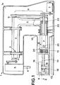
- Figure 1 is a sectional elevation of some of its elements.
- FIG. 2 is a section, on a larger scale, along II-II of FIG. 1.
- the sewing machine visible in FIG. 1 has a housing 1 formed by assembling two shells, such as shell 1 a , which also constitutes one of the two elements of the frame of the machine, like this which is described and illustrated in Swiss Patent No. 675,600 previously cited.
- Such a frame is, in fact, constituted by this shell 1a and by a resistant U-shaped frame, 2, being, in this case, in the form of a tubular body of hexagonal section and fixed removably on this shell thanks to three devices generically indicated by the reference 3 and whose structural particularities are the subject of the international patent application PCT / CH91 / 00119 filed on 17.5.1991.
- This sewing machine usually comprises, in particular, a needle bar 4, a mechanism 5 for controlling the needle bar, mechanism for driving the material to be sewn and a loop sensor device, the structural features of which have been shown. schematically in FIG. 2 and which are essentially arranged in a housing 6.
- the organs mentioned are traditionally driven from a motor 7 by means of a set of pulleys and belts, indicated generically by the reference 8, driving two motor shafts 9 and 10 respectively and passing through the upper arm of the frame 2, for the shaft 9, and the lower arm of the latter, for the shaft 10.
- the pivoting and maintaining in a centered and horizontal position of the axis 9 in the upper arm of the framework are ensured by two ball bearings mounted inside this arm for example as described in Swiss Patent No. 675,600 which will be referred to for more details.
- the sewing machine shown in FIG. 1 is of the type in which the amplitude and the direction of drive of the sewing material are controlled by an electric motor, in particular a stepping motor, slaved to an electronic control circuit. .
- This technique is well known to those skilled in the art since it has been used for many years.
- the stepping motor 11 carries the housing 6 which is fixed to the motor for example by a series of screws of which only the axes 12 are visible in the drawing (fig. 2).
- the motor 11 comprises a shaft 13 passing through a passage 14 of the housing 6 and at the end of which is cut a pinion 15 engaged with a toothed crown 17 * formed on the periphery of the first mobile 15 * of a device for controlling the range and direction of movement imparted to a claw 8 for driving the material to be sewn.
- the housing 6 in particular contains a rotary hook 16 mounted at the upper end of a pinion 17 rotating on a shaft 17a, sketched in broken lines and secured, in 18, to the bottom of the housing 6.
- the pinion 17 meshes with a second pinion 19 secured to the shaft 10 (FIG. 2) on which the drive of the hook 16 depends.
- the shaft 10 rotates in two bearings, that is a first, smooth bearing, 20, engaged in a passage 21 formed in the wall of the housing 6 (fig. 2), and a second bearing , ball, 22, driven into the opening of the right end of a sleeve 23 whose left end is secured to a flange 24 (fig. 1).
- This sleeve 23 is fixed to the motor 11 by means of this flange and of the screws already mentioned, of which only the longitudinal axes 12 are shown.
- the arms of the frame 2 are tubular and of hexagonal section.
- the external profile of the sleeve 23 is chosen so that it can be easily introduced into the lower arm of the frame 2, by simple sliding. It can be locked in the fully engaged position in the framework by a screw 25 passing through an opening in the wall of this framework and engaging in a threaded hole provided in the body of the sleeve 23.
- this opening could be in the form of a slot extending parallel to the longitudinal axis of the lower arm of the frame 2, thus making it possible to fix the sleeve 23 in a position more or less engaged in the framework: in doing so, it will be possible to move the hook 16 laterally with respect to the needle, not shown, that the needle bar 4 carries, in particular for making adjustments if necessary.
- the invention described makes it possible to rationalize, to a very great extent, the manufacture and assembly of the structural members allocated in the traditional way to the lower arm of a sewing machine: in particular, provision may be made for the manufacture and assembly of the assembly comprising the housing 6 and the organs it contains, the motor 11 and the sleeve 23, independently of the rest of the sewing machine, the whole constituting an autonomous unit which can be easily mounted on the resistant framework of this machine as previously mentioned.
- such a unit can, if necessary, be dismantled just as easily, in particular to replace it, in the event of a breakdown, with a similar unit.
Landscapes
- Engineering & Computer Science (AREA)
- Textile Engineering (AREA)
- Sewing Machines And Sewing (AREA)
Abstract
Description
- La présente invention concerne les machines à coudre comprenant un bâti présentant deux bras auxquels sont associés au moins, pour le premier bras, une barre-aiguille et son mécanisme d'entraînement et, pour le second bras, un dispositif capteur de boucle, le mécanisme d'entraînement de celui-ci et un mécanisme d'entraînement du matériau à coudre.
- Elle a, plus particulièrement, pour objet une machine de ce type dans laquelle l'amplitude et la direction de l'entraînement du matériau à coudre sont commandées par un moteur électrique asservi à un circuit électronique de pilotage.
- Certaines de ces machines comportent un bâti monolytique, en fonte injectée, sur lequel les divers composants cités doivent être fixés individuellement et faire ensuite l'objet des réglages requis pour chacun d'eux dans le contexte de l'ensemble technique dont ils font partie.
- On conçoit que la fabrication et le montage de telles machines requière une main d'oeuvre et des installations importantes, donc coûteuses.
- La déposante s'est appliquée à rechercher des solutions techniques permettant de limiter, voire d'écarter, les inconvénients ci-dessus, tout en maintenant, voire en améliorant, la qualité de ses produits.
- Elle a notamment proposé une nouvelle architecture de l'ensemble de l'ossature d'une machine à coudre et de son boîtier (voir notamment le brevet suisse N° 675 600), une construction plus rationnelle du mécanisme d'entraînement de la barre-aiguille, tant dans ses déplacements axiaux que dans ses mouvements de jetée (voir le document EP 0 377 403), le tout se présentant sous forme d'une unité autonome susceptible d'être montée et réglée indépendamment du montage final de la machine, une architecture inédite du presse-étoffe et de ses organes de commande, constituant également une unité autonome présentant des avantages similaires à ceux du nouveau mécanisme d'entraînement de la barre-aiguille (voir le document EP 0 370 965).
- Dans le brevet suisse ci-dessus, l'ossature résistante se présente sous forme tubulaire et est constituée par assemblage de deux coquilles obtenues par étampage, entre lesquelles on intègre un arbre-moteur et ses paliers. Cette dernière possibilité s'est révélée être particulièrement avantageuse, notamment dans la constitution d'une unité dans laquelle l'arbre et ses paliers sont ceux destinés à la commande de la barre-aiguille de la machine à coudre, éléments qui sont ainsi associés à l'ossature dès sa fabrication, plus particulièrement au bras supérieur de l'ossature.
- La déposante vise maintenant à améliorer la rationalisation de la fabrication et du montage des éléments et organes associés traditionnellement au bras inférieur d'une machine à coudre du type cité ci-dessus se caractérisant, toutefois, par le fait que le dispositif capteur de boucle, son mécanisme d'entraînement et ledit mécanisme d'entraînement du matériau à coudre sont montés sur un support intermédiaire et par le fait qu'elle comprend des moyens de fixation de ce support sur le corps du moteur et des moyens de fixation du corps du moteur sur le second bras du bâti.
- Les dessins annexés en représentent schématiquement une forme d'exécution, donnée à titre d'exemple.
- La figure 1 est une élévation en coupe de certains de ses éléments.
- La figure 2 est une coupe, à plus grande échelle, selon II-II de la figure 1.
- La machine à coudre visible sur la figure 1 présente un boîtier 1 formé par assemblage de deux coquilles, telle la coquille 1a, laquelle constitue, de plus, l'un des deux éléments du bâti de la machine, à l'image de ce qui est décrit et illustré dans le brevet suisse N° 675 600 précédemment cité.
- Un tel bâti est, en effet, constitué par cette coquille la et par une ossature résistante en U, 2, se présentant, en l'espèce, sous la forme d'un corps tubulaire de section hexagonale et fixée amoviblement sur cette coquille grâce à trois dispositifs indiqués génériquement par la référence 3 et dont les particularités structurelles font notamment l'objet de la demande de brevet internationale PCT/CH91/00119 déposée le 17.5.1991.
- Cette machine à coudre comporte, de façon usuelle, notamment une barre-aiguille 4, un mécanisme 5 de commande de la barre-aiguille, ion mécanisme d'entraînement du matériau à coudre et un dispositif capteur de boucle dont les particularités structurelles ont été représentées schématiquement sur la figure 2 et qui sont disposées, pour l'essentiel, dans un boîtier 6.
- Les organes cités sont entraînés, de façon traditionnelle, à partir d'un moteur 7 par l'intermédiaire d'un jeu de poulies et de courroies, indiqué de façon générique par la référence 8, entraînant deux arbres moteurs 9 et 10 respectivement et traversant le bras supérieur de l'ossature 2, pour l'arbre 9, et le bras inférieur de celle-ci, pour l'arbre 10. Le pivotement et le maintien en position centrée et horizontale de l'axe 9 dans le bras supérieur de l'ossature sont assurés grâce à deux paliers à billes montés à l'intérieur de ce bras par exemple de la manière décrite dans le brevet suisse N° 675 600 auquel on se référera pour plus de détails.
- En ce qui concerne l'arbre 10, celui-ci est monté dans le bras inférieur de l'ossature 2 de la manière qui sera décrite ci-après.
- La machine à coudre représentée sur la figure 1 est du type dans lequel l'amplitude et le sens d'entraînement du matériau à coudre sont commandés par un moteur électrique, notamment un moteur pas-à-pas, asservi à un circuit électronique de pilotage. Cette technique est bien connue de l'homme du métier puisqu'elle a été mise en oeuvre depuis nombre d'années.
- Le moteur pas-à-pas 11 porte le boîtier 6 qui est fixé sur le moteur par exemple par une série de vis dont seuls les axes 12 sont visibles au dessin (fig. 2).
- Le moteur 11 comporte un arbre 13 traversant un passage 14 du boîtier 6 et à l'extrémité duquel est taillé un pignon 15 en prise avec une couronne dentée 17* formée sur le pourtour du premier mobile 15* d'un dispositif de commande de l'amplitude et du sens du mouvement imparti à une griffe 8pour l'entraînement du matériau à coudre.

- Les divers éléments de ce dispositif sont indiqués par des références assorties d'un * : leur structure propre ainsi que l'assemblage fonctionnel dont ils font partie sont décrits dans le document EP o 374 090 auquel on se référera pour plus de détails. Dans ce brevet, les éléments homologues de ceux représentés en figure 2 sont caractérisés par des références identiques dépourvues de l'astérisque.
- En plus des éléments ci-dessus, le boîtier 6 renferme notamment un crochet rotatif 16 monté à l'extrémité supérieure d'un pignon 17 tournant sur un arbre 17a, esquissé en traits interrompus et solidaire, en 18, du fond du boîtier 6. Le pignon 17 engrène avec un second pignon 19 solidaire de l'arbre 10 (fig. 2) dont dépend l'entraînement du crochet 16.
- Il convient, à ce point, de relever que l'arbre 10 tourne dans deux paliers, soit un premier palier, lisse, 20, engagé dans un passage 21 ménagé dans la paroi du boîtier 6 (fig. 2), et un second palier, à billes, 22, chassé dans l'ouverture de l'extrémité droite d'un manchon 23 dont l'extrémité gauche est solidaire d'un flasque 24 (fig. 1).
- Ce manchon 23 est fixé au moteur 11 par l'intermédiaire de ce flasque et des vis déjà citées dont seuls les axes longitudinaux 12 sont représentés.
- Dans la forme d'exécution représentée, les bras de l'ossature 2, notamment, sont tubulaires et de section hexagonale. Avantageusement, le profil externe du manchon 23 est choisi de sorte qu'il puisse être introduit facilement dans le bras inférieur de l'ossature 2, par simple coulissement. Il peut être bloqué en position entièrement engagée dans l'ossature par une vis 25 traversant une ouverture ménagée dans la paroi de cette ossature et faisant prise dans un trou fileté prévu dans le corps du manchon 23.
- En variante, cette ouverture pourrait se présenter sous la forme d'une fente s'étendant parallèlement à l'axe longitudinal du bras inférieur de l'ossature 2, permettant ainsi de fixer le manchon 23 dans une position plus ou moins engagée dans l'ossature : il sera, ce faisant, possible de déplacer latéralement le crochet 16 par rapport à l'aiguille, non représentée, que porte la barre-aiguille 4, notamment pour procéder à des réglages si nécessaire.
- L'invention décrite permet de rationaliser, dans une très grande mesure, la fabrication et le montage des organes structurels alloués de façon traditionnelle au bras inférieur d'une machine à coudre : en particulier, on pourra prévoir la fabrication et le montage de l'ensemble comprenant le boîtier 6 et les organes qu'il contient, le moteur 11 et le manchon 23, indépendamment du reste de la machine à coudre, le tout constituant une unité autonome que l'on pourra monter facilement sur l'ossature résistante de cette machine de la manière citée précédemment.
- Réciproquement, une telle unité pourra, au besoin, être démontée tout aussi facilement, notamment pour procéder à son remplacement, en cas de panne, par une unité similaire.
Claims (3)
- Machine à coudre, comprenant un bâti présentant deux bras auxquels sont associés au moins, pour le premier bras, une barre-aiguille et son mécanisme de commande et, pour le second bras, un dispositif capteur de boucle, le mécanisme d'entraînement de celui-ci et un mécanisme d'entraînement du matériau à coudre, machine dans laquelle l'amplitude et la direction de cet entraînement sont commandées par un moteur électrique asservi à un circuit électronique de pilotage, caractérisée par le fait que le dispositif capteur de boucle, son mécanisme d'entraînement et ledit mécanisme d'entraînement du matériau à coudre sont montés sur un support intermédiaire et par le fait qu'elle comprend des moyens de fixation de ce support sur le corps du moteur et des moyens de fixation du corps du moteur sur le second bras du bâti.
- Machine à coudre selon la revendication 1, dans laquelle au moins le second bras du bâti présente une structure tubulaire, et dans laquelle le mécanisme d'entraînement présente au moins un arbre rotatif s'étendant à l'intérieur du second bras et monté tournant dans au moins deux paliers, caractérisée par le fait que les moyens de fixation du corps du moteur sur le second bras comprennent au moins un manchon engagé à coulissement dans l'ouverture du second bras, des premiers organes de fixation de ce support sur le corps du moteur et des seconds organes de fixation dudit support sur le second bras, et par le fait que l'arbre traverse le manchon et que lesdits paliers sont solidaires, l'un, dudit support intermédiaire et, l'autre, dudit manchon.
- Machine à coudre selon les revendications 1 et 2, caractérisée par le fait que ledit support intermédiaire, le dispositif capteur de boucle, son mécanisme d'entraînement, le mécanisme d'entraînement du matériau à coudre, ledit moteur électrique, le manchon et lesdits moyens de fixation forment une unité autonome et amovible.
Applications Claiming Priority (2)
| Application Number | Priority Date | Filing Date | Title |
|---|---|---|---|
| CH3781/90A CH684418A5 (fr) | 1990-11-29 | 1990-11-29 | Machine à coudre. |
| CH3781/90 | 1990-11-29 |
Publications (2)
| Publication Number | Publication Date |
|---|---|
| EP0488955A1 true EP0488955A1 (fr) | 1992-06-03 |
| EP0488955B1 EP0488955B1 (fr) | 1995-02-08 |
Family
ID=4263348
Family Applications (1)
| Application Number | Title | Priority Date | Filing Date |
|---|---|---|---|
| EP91810917A Expired - Lifetime EP0488955B1 (fr) | 1990-11-29 | 1991-11-26 | Bâti de machine à coudre |
Country Status (9)
| Country | Link |
|---|---|
| US (1) | US5205230A (fr) |
| EP (1) | EP0488955B1 (fr) |
| JP (1) | JPH04272789A (fr) |
| CN (1) | CN1027550C (fr) |
| BR (1) | BR9105189A (fr) |
| CH (1) | CH684418A5 (fr) |
| DE (1) | DE69107289T2 (fr) |
| ES (1) | ES2069263T3 (fr) |
| RU (1) | RU2023777C1 (fr) |
Families Citing this family (8)
| Publication number | Priority date | Publication date | Assignee | Title |
|---|---|---|---|---|
| CN1090690C (zh) * | 1996-12-10 | 2002-09-11 | 大和缝纫机制造株式会社 | 筒式底板型缝纫机 |
| JP3480805B2 (ja) * | 1998-02-09 | 2003-12-22 | ブラザー工業株式会社 | ミシンの回転釜駆動装置 |
| DE19907007A1 (de) * | 1999-02-18 | 2000-08-24 | Zsk Stickmasch Gmbh | Einstellbarer Greifer |
| RU2181394C2 (ru) * | 2000-03-14 | 2002-04-20 | Московский государственный университет сервиса | Шьющий модуль к швейным агрегатам модульного типа |
| JP2002273081A (ja) * | 2001-03-19 | 2002-09-24 | Brother Ind Ltd | 送り調節器組立体、布送り機構付き釜モジュール、布送り機構付き釜モジュールを備えたミシン |
| JP4799772B2 (ja) * | 2001-07-17 | 2011-10-26 | Juki株式会社 | 筒型ミシン |
| AU2003233811A1 (en) * | 2003-05-28 | 2005-01-21 | Del Vecchia And Quintanar, S.L. | System for synchronising two movements and sewing machine comprising same |
| CN115787212B (zh) * | 2023-02-01 | 2023-05-02 | 海安迪斯凯瑞探测仪器有限公司 | 一种基于机器人的联动缝纫头 |
Citations (6)
| Publication number | Priority date | Publication date | Assignee | Title |
|---|---|---|---|---|
| DE817837C (de) * | 1950-05-03 | 1951-10-22 | Betr Smittelbau G M B H | Naehmaschine mit Stofftragarm und Stoffvorschubeinrichtung |
| US2709978A (en) * | 1950-10-02 | 1955-06-07 | Adler Solomon | Sewing machine |
| US3012532A (en) * | 1958-02-03 | 1961-12-12 | Leslie Ivan Alexander | Sewing machines |
| GB2175616A (en) * | 1985-05-27 | 1986-12-03 | Rockwell Rimoldi Spa | Sewing machine with a base consisting of two modules detachably connected to each other |
| DE3812725A1 (de) * | 1986-10-21 | 1989-02-02 | Baeckmann Reinhard | Verfahren und einrichtung zur ueberwachung und optimierung von naehmaschinen, naehautomaten und naehprozessen |
| EP0337952A1 (fr) * | 1988-04-14 | 1989-10-18 | Mefina S.A. | Machine à coudre |
Family Cites Families (10)
| Publication number | Priority date | Publication date | Assignee | Title |
|---|---|---|---|---|
| DE1082485B (de) * | 1955-12-21 | 1960-05-25 | Naehmaschinenfabrik Karlsruhe | Freiarmnaehmaschine mit abnehmbarem Armendstueck |
| US3866553A (en) * | 1973-05-07 | 1975-02-18 | Singer Co | Sewing machine frame construction |
| US4183310A (en) * | 1978-12-21 | 1980-01-15 | The Singer Company | Feed and loop taker module for a sewing machine |
| US4193361A (en) * | 1978-12-21 | 1980-03-18 | The Singer Company | Sewing machine construction utilizing subassemblies |
| IT1151007B (it) * | 1980-03-31 | 1986-12-17 | Rockwell Rimoldi Spa | Macchina per cucire modulare |
| US4552081A (en) * | 1985-06-03 | 1985-11-12 | The Singer Company | Skeletal frame sewing machine |
| CH677804A5 (fr) * | 1988-11-30 | 1991-06-28 | Mefina Sa | |
| CH677508A5 (fr) * | 1988-11-30 | 1991-05-31 | Mefina Sa | |
| CH676999A5 (fr) * | 1988-11-30 | 1991-03-28 | Mefina Sa | |
| CH683353A5 (fr) * | 1990-05-23 | 1994-02-28 | Mefina Sa | Machine à coudre. |
-
1990
- 1990-11-29 CH CH3781/90A patent/CH684418A5/fr not_active IP Right Cessation
-
1991
- 1991-11-26 CN CN91111212.XA patent/CN1027550C/zh not_active Expired - Fee Related
- 1991-11-26 EP EP91810917A patent/EP0488955B1/fr not_active Expired - Lifetime
- 1991-11-26 ES ES91810917T patent/ES2069263T3/es not_active Expired - Lifetime
- 1991-11-26 DE DE69107289T patent/DE69107289T2/de not_active Expired - Fee Related
- 1991-11-28 BR BR919105189A patent/BR9105189A/pt not_active Application Discontinuation
- 1991-11-28 RU SU915010171A patent/RU2023777C1/ru active
- 1991-11-29 JP JP3316236A patent/JPH04272789A/ja active Pending
- 1991-11-29 US US07/798,929 patent/US5205230A/en not_active Expired - Fee Related
Patent Citations (6)
| Publication number | Priority date | Publication date | Assignee | Title |
|---|---|---|---|---|
| DE817837C (de) * | 1950-05-03 | 1951-10-22 | Betr Smittelbau G M B H | Naehmaschine mit Stofftragarm und Stoffvorschubeinrichtung |
| US2709978A (en) * | 1950-10-02 | 1955-06-07 | Adler Solomon | Sewing machine |
| US3012532A (en) * | 1958-02-03 | 1961-12-12 | Leslie Ivan Alexander | Sewing machines |
| GB2175616A (en) * | 1985-05-27 | 1986-12-03 | Rockwell Rimoldi Spa | Sewing machine with a base consisting of two modules detachably connected to each other |
| DE3812725A1 (de) * | 1986-10-21 | 1989-02-02 | Baeckmann Reinhard | Verfahren und einrichtung zur ueberwachung und optimierung von naehmaschinen, naehautomaten und naehprozessen |
| EP0337952A1 (fr) * | 1988-04-14 | 1989-10-18 | Mefina S.A. | Machine à coudre |
Also Published As
| Publication number | Publication date |
|---|---|
| DE69107289D1 (de) | 1995-03-23 |
| BR9105189A (pt) | 1992-07-21 |
| ES2069263T3 (es) | 1995-05-01 |
| DE69107289T2 (de) | 1995-07-13 |
| JPH04272789A (ja) | 1992-09-29 |
| EP0488955B1 (fr) | 1995-02-08 |
| CH684418A5 (fr) | 1994-09-15 |
| RU2023777C1 (ru) | 1994-11-30 |
| CN1062011A (zh) | 1992-06-17 |
| CN1027550C (zh) | 1995-02-01 |
| US5205230A (en) | 1993-04-27 |
Similar Documents
| Publication | Publication Date | Title |
|---|---|---|
| EP0488955B1 (fr) | Bâti de machine à coudre | |
| FR2527132A1 (fr) | Tete articulee pour robot industriel | |
| EP3719187B1 (fr) | Dispositif de formation de la foule et métier à tisser de type jacquard incorporant un tel dispositif | |
| EP0377403B1 (fr) | Machine à coudre zig-zag | |
| EP0229681B1 (fr) | Dispositif d'entraînement en rotation du tube d'enroulage d'un store à rouleau, volet roulant ou similaire | |
| EP1903133B1 (fr) | Dispositif de commande de lance flexible et métier à tisser incorporant au moins un tel dispositif | |
| FR2528301A1 (fr) | Batteur a fouets | |
| EP0869858B1 (fr) | Unite d'usinage a tete rotative | |
| FR2510435A1 (fr) | Machine de formage a rouleaux avec des tetes reglables dans la direction longitudinale | |
| FR2689560A3 (fr) | Dispositif de commande automatique de porte. | |
| EP1743058B1 (fr) | Dispositif de nivelage, mecanique d'armure a came incorporant un tel dispositif et metier a tisser equipe d'une telle mecanique | |
| CH713222A1 (fr) | Mouvement horloger à remontage automatique. | |
| FR2606390A1 (fr) | Entrainement d'ascenseur a engrenage et vis sans fin et procede d'assemblage | |
| FR2631213A1 (fr) | Gaveuse semi-automatique | |
| CH437216A (fr) | Mélangeur à cuve fixe | |
| FR2574145A1 (fr) | Dispositif pour la transmission d'un mouvement rotatif,notamment sur une machine-outil | |
| EP0478439A1 (fr) | Machine adaptée à la fabrication de vis rectifiées à partir de barres à tailler | |
| FR2508564A1 (fr) | Dispositif de reglage des aubes directrices d'une turbomachine axiale | |
| FR2661963A1 (fr) | Reducteur de vitesse a train epicyclouidal. | |
| FR2732237A1 (fr) | Melangeur motorise | |
| FR2664491A1 (fr) | Appareil de faconnage, pour elements dentaires, comportant un dispositif de protection. | |
| FR2746327A1 (fr) | Melangeur a bac annulaire | |
| FR2587643A1 (fr) | Unite de translation et de rotation d'une tete de travail de machine, notamment de robot | |
| BE719249A (fr) | ||
| FR2670001A1 (fr) | Boussole. |
Legal Events
| Date | Code | Title | Description |
|---|---|---|---|
| PUAI | Public reference made under article 153(3) epc to a published international application that has entered the european phase |
Free format text: ORIGINAL CODE: 0009012 |
|
| AK | Designated contracting states |
Kind code of ref document: A1 Designated state(s): CH DE ES FR GB IT LI SE |
|
| 17P | Request for examination filed |
Effective date: 19920702 |
|
| 17Q | First examination report despatched |
Effective date: 19931027 |
|
| GRAA | (expected) grant |
Free format text: ORIGINAL CODE: 0009210 |
|
| AK | Designated contracting states |
Kind code of ref document: B1 Designated state(s): CH DE ES FR GB IT LI SE |
|
| REF | Corresponds to: |
Ref document number: 69107289 Country of ref document: DE Date of ref document: 19950323 |
|
| GBT | Gb: translation of ep patent filed (gb section 77(6)(a)/1977) |
Effective date: 19950328 |
|
| REG | Reference to a national code |
Ref country code: ES Ref legal event code: FG2A Ref document number: 2069263 Country of ref document: ES Kind code of ref document: T3 |
|
| ITF | It: translation for a ep patent filed | ||
| PG25 | Lapsed in a contracting state [announced via postgrant information from national office to epo] |
Ref country code: GB Effective date: 19951126 |
|
| PG25 | Lapsed in a contracting state [announced via postgrant information from national office to epo] |
Ref country code: SE Effective date: 19951127 Ref country code: ES Free format text: LAPSE BECAUSE OF THE APPLICANT RENOUNCES Effective date: 19951127 |
|
| PG25 | Lapsed in a contracting state [announced via postgrant information from national office to epo] |
Ref country code: LI Effective date: 19951130 Ref country code: CH Effective date: 19951130 |
|
| PLBE | No opposition filed within time limit |
Free format text: ORIGINAL CODE: 0009261 |
|
| STAA | Information on the status of an ep patent application or granted ep patent |
Free format text: STATUS: NO OPPOSITION FILED WITHIN TIME LIMIT |
|
| 26N | No opposition filed | ||
| REG | Reference to a national code |
Ref country code: CH Ref legal event code: PL |
|
| GBPC | Gb: european patent ceased through non-payment of renewal fee |
Effective date: 19951126 |
|
| PG25 | Lapsed in a contracting state [announced via postgrant information from national office to epo] |
Ref country code: FR Effective date: 19960731 |
|
| PG25 | Lapsed in a contracting state [announced via postgrant information from national office to epo] |
Ref country code: DE Effective date: 19960801 |
|
| EUG | Se: european patent has lapsed |
Ref document number: 91810917.4 |
|
| REG | Reference to a national code |
Ref country code: FR Ref legal event code: ST |
|
| REG | Reference to a national code |
Ref country code: ES Ref legal event code: FD2A Effective date: 20010402 |
|
| PG25 | Lapsed in a contracting state [announced via postgrant information from national office to epo] |
Ref country code: IT Free format text: LAPSE BECAUSE OF NON-PAYMENT OF DUE FEES;WARNING: LAPSES OF ITALIAN PATENTS WITH EFFECTIVE DATE BEFORE 2007 MAY HAVE OCCURRED AT ANY TIME BEFORE 2007. THE CORRECT EFFECTIVE DATE MAY BE DIFFERENT FROM THE ONE RECORDED. Effective date: 20051126 |