EP0488966B1 - Absperrvorrichung für Gasrohrleitungen - Google Patents
Absperrvorrichung für Gasrohrleitungen Download PDFInfo
- Publication number
- EP0488966B1 EP0488966B1 EP91830516A EP91830516A EP0488966B1 EP 0488966 B1 EP0488966 B1 EP 0488966B1 EP 91830516 A EP91830516 A EP 91830516A EP 91830516 A EP91830516 A EP 91830516A EP 0488966 B1 EP0488966 B1 EP 0488966B1
- Authority
- EP
- European Patent Office
- Prior art keywords
- rod
- pipe
- cup
- shaped body
- axis
- Prior art date
- Legal status (The legal status is an assumption and is not a legal conclusion. Google has not performed a legal analysis and makes no representation as to the accuracy of the status listed.)
- Revoked
Links
- 230000000903 blocking effect Effects 0.000 claims abstract description 7
- 230000006835 compression Effects 0.000 claims description 6
- 238000007906 compression Methods 0.000 claims description 6
- 239000013536 elastomeric material Substances 0.000 claims description 2
- 230000001154 acute effect Effects 0.000 claims 2
- 235000009854 Cucurbita moschata Nutrition 0.000 claims 1
- 240000001980 Cucurbita pepo Species 0.000 claims 1
- 235000009852 Cucurbita pepo Nutrition 0.000 claims 1
- 230000005540 biological transmission Effects 0.000 claims 1
- 235000020354 squash Nutrition 0.000 claims 1
- 238000007789 sealing Methods 0.000 description 8
- 238000005553 drilling Methods 0.000 description 2
- 230000008878 coupling Effects 0.000 description 1
- 238000010168 coupling process Methods 0.000 description 1
- 238000005859 coupling reaction Methods 0.000 description 1
- 239000004519 grease Substances 0.000 description 1
- 238000005461 lubrication Methods 0.000 description 1
- 239000002184 metal Substances 0.000 description 1
- 238000005096 rolling process Methods 0.000 description 1
Images



Classifications
-
- F—MECHANICAL ENGINEERING; LIGHTING; HEATING; WEAPONS; BLASTING
- F16—ENGINEERING ELEMENTS AND UNITS; GENERAL MEASURES FOR PRODUCING AND MAINTAINING EFFECTIVE FUNCTIONING OF MACHINES OR INSTALLATIONS; THERMAL INSULATION IN GENERAL
- F16L—PIPES; JOINTS OR FITTINGS FOR PIPES; SUPPORTS FOR PIPES, CABLES OR PROTECTIVE TUBING; MEANS FOR THERMAL INSULATION IN GENERAL
- F16L55/00—Devices or appurtenances for use in, or in connection with, pipes or pipe systems
- F16L55/10—Means for stopping flow in pipes or hoses
- F16L55/12—Means for stopping flow in pipes or hoses by introducing into the pipe a member expandable in situ
- F16L55/124—Means for stopping flow in pipes or hoses by introducing into the pipe a member expandable in situ introduced radially into the pipe or hose
Definitions
- the present invention relates to a device for temporarily blocking gas pipes.
- obturator balloons are introduced in the deflated configuration, under gas-tight conditions, through sleeves which are welded to the pipe at right angles. This solution is not reliable for medium and high-pressure pipes.
- US-A-4 202 377 discloses a device for temporarily blocking high or medium pressure gas pipes, having the features indicated in the pre-characterising portion of appended claim 1.
- the object of the present invention is to provide a blocking device which can cut off the gas supply to a portion of a medium-pressure pipe without the need to cut off the supply to the entire pipe.
- the cup-shaped bodies of the blocking devices containing the angled obturating ends, are mounted on the sleeves with the interposition of flat valves with disc obturators.
- each rod is then slid so that its angled obturating end is positioned in the pipe.
- the seal is then expanded radially by the operating means so as to lock the angled end of each rod within the pipe and form a perfect seal between the seal and the pipe so that work can be carried out safely on the isolated portion of the pipe without any danger of gas leaks.
- the circular seal is annular and has an isosceles trapezoidal cross-section.
- a device, generally indicated 10, for temporarily blocking medium-pressure gas pipes T is used to cut off the supply of gas to an intermediate portion T1 of pipe.
- the device 10 includes a cup-shaped body 12 with an end wall 12a having a central hole 14 in which a hollow rod 18, the function of which will be explained in the following description, is sealingly slidable and can be inclined with the interposition of an annular seal 16 of the O- ring type.
- the cup-shaped body 12 has a threaded mouth 12b which can be screwed onto a connector R of a gate valve V of the type with a disc obturator P.
- the mouth 12b of the cup-shaped body 12 may alternatively have a flange 2 for coupling to the valve V.
- the gate valve V in turn is mounted on a connecting sleeve M which is welded at right angles to the pipe T at S and in correspondence with which a through-hole F has been formed by a suitable pipe-drilling machine.
- the hollow rod 18 has a first end 18a to which a circular flange 20 with guide holes 20a is fixed in an angled position.
- the flange 20 has a conical front surface 22 facing a corresponding conical surface 24 of a compression disc 26 having guide pins 26a which are slidable in the guide holes 20a in the flange 20.
- a sealing ring 28 of elastomeric material with a trapezoidal cross-section is interposed between the flange 20 and the compression disc 26 and is adapted to be acted upon axially by the flange 20 and by the compression disc 26.
- the sealing ring 28 has an outside diameter substantially corresponding to the inside diameter of the pipe T.
- the rod 18 has a second end 18b with an external thread onto which is screwed a corresponding threaded sleeve 30 which can be operated manually by a hand wheel 32.
- the sleeve 30 has an internal annular shoulder 30a against which a traction bush 36 bears with the interposition of a thrust ball bearing 34, a first end 38a of a metal cable 38 being fixed to the bush 36 and its second end 38b being connected to the compression disc 26.
- a tubular locating element 40 slidable outside the rod 18 has two screws 42 for fixing it to the rod 18, as well as a control and locating rod 44, and an inclined end surface 46 which is intended to abut the outer surface 48 of the end wall 12a of the cup-shaped body 12.
- the sealing ring 16 In order to prevent gas leaks, in addition to the sealing ring 16, there are O-ring-type sealing rings 43, 45 and 47 between the operating portion 32 and the threaded sleeve 30, between the threaded sleeve 30 and the rod 18, and between the cup-shaped body 12 and the gate valve V, respectively.
- the cup-shaped body 12 also has a valve 50 for letting off the gas trapped in the cup-shaped body 12 upon completion of the operation on the portion of pipe T1.
- Figure 2 shows the mounting of the device 10 on the gate valve V which is in the closed configuration.
- the end 18a of the rod 18 is housed completely within the cup-shaped body 12.
- the gate obturator P is opened so that the rod 12 can slide and simultaneously rotate so as to be positioned as shown in Figure 3.
- the tubular element 40 which is fixed in a predetermined position on the rod 18 beforehand, enables the rod 18 to be positioned at an optimal inclination, preferably about 7° to the axis X-X of the cup-shaped body 12, and the flange 20 to be arranged perpendicular to the axis of the pipe T, by lining up the control rod 44 of the tubular element 40 with the pipe T (the control rod 44 should be within the plane in which the pipe T lies).
- the operator then deforms the sealing ring 28 by means of the hand wheel 32 so as to pull the cable 38 which passes around a transverse pin 52 at the end 18a of the rod 18 ( Figure 3).
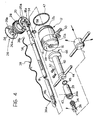
- the side of the rod 18 has a grease hole 54 (Fig. 4) which can be closed, in the configuration of use, by a slidable sleeve 56 which is locked in position by the resilient ring 58.
- a closure plug (not shown) may be screwed, and perhaps subsequently welded, into an internal thread A in the sleeve M which is welded to the pipe T so that the gate valve V can then be removed.
- the sealing ring 28 may be resiliently deformed by a mechanical male-and-female screw system instead of by the cable 38.
- This control system is used in the embodiment shown in Figure 5.
- the pressure disc 26 has an axial threaded shank 70 which is engaged in a female threaded member 71.
- the female threaded member 71 is mounted so as to be freely rotatable in the structure of the end portion 18a by means of a rolling bearing 72 and is integral with a bevel pinion 73 which meshes with a bevel pinion 74.
- the bevel pinion 74 is fixed to one end of a shaft 75 which is rotatable in the rod 18.
- the opposite end of the shaft 75 can be rotated by a lever 32a (shown in broken outline), preferably with the interposition of a ratchet mechanism of any known type (not shown in detail) so that the shaft 75 can be rotated continuously by successively pivoting the lever 32a to and fro.
- the tubular element 40 is not used and the correct angular positioning of the device is achieved solely with reference to a hand grip 44a.
- the cup 18 has a valve 76 of known type for diverting the gas to a by-pass pipe.
Landscapes
- Engineering & Computer Science (AREA)
- General Engineering & Computer Science (AREA)
- Mechanical Engineering (AREA)
- Pipe Accessories (AREA)
- Pipeline Systems (AREA)
- Glass Compositions (AREA)
- Filling Or Discharging Of Gas Storage Vessels (AREA)
- Sampling And Sample Adjustment (AREA)
Claims (8)
- Vorrichtung zum vorübergehenden Absperren von Gasrohrleitungen, mit:- einem becherförmigen Körper (12) zur Befestigung an einer Büchse (M), welche in einem rechten Winkel an einem Durchgangsloch (F), welches in der Rohrleitung (T) vorgesehen ist, an die Rohrleitung (T) geschweißt ist,- einer Stange (18), welche in einem Loch (14) in einer Stirnwand (12a) des becherförmigen Körpers (12) gleitend, abdichtend und zentral vorgesehen ist und ein gewinkeltes, abdichtendes Ende (18a) mit einem Flansch (20, 26) aufweist, welcher in einer Ebene angeordnet und mit einer runden Dichtung (28) aus elastischem Material verbunden ist, welche Dichtung einen Außendurchmesser besitzt, der im wesentlichen dem Innendurchmesser der Rohrleitung (T) entspricht, welche Stange (18) eine erste Position einnehmen kann, in welcher ihr gewinkeltes Ende (18a) im becherförmigen Körper (12) untergebracht ist, und eine zweite Position einnehmen kann, in welcher die Stange (18) mit ihrer Achse so angeordnet ist, daß sie mit der Achse der Rohrleitung (T) eine gemeinsamer Ebene bildet, und in welcher ihr gewinkeltes, abdichtendes Ende (18a) in die Rohrleitung (T) wie ein Stopfen eingeschoben ist, und- Bedienungsmitteln (32, 30, 38, 20, 22) zum Expandieren der Dichtung (28) in radialer Richtung gegen die Wand der Rohrleitung (T), wenn das gewinkelte Ende (18a) der Stange (18) in ihrer zweiten Position ist,
dadurch gekennzeichnet, daß- das abdichtende Ende (18a) so an der Stange (18) fixiert ist, daß die Achse der Stange (18) einen vorbestimmten, spitzen Winkel zur Ebene des Flansches (20, 26) des abdichtenden Endes (18a) bildet,- und daß der becherförmige Körper (12) so geformt ist, daß, wenn die Stange (18) in ihrer zweiten Position ist, die Stange (18) gleichzeitig an gegenüberliegenden Stellen hinsichtlich ihrer Achse anstößt, korrespondierend mit dem Loch (14) in der Stirnwand (12a) des becherförmigen Körpers (12), und gegen eine Kante des Durchgangsloches (F), welches in der Rohrleitung (T) vorgesehen ist,- so daß die Achse der Stange (18) mit der Achse der Rohrleitung (T) einen im wesentlichen komplementären Winkel zum spitzen Winkels bildet, wodurch sich der Flansch (20, 26) des abdichtenden Endes (18a) selbst im rechten Winkel zur Achse der Rohrleitung (T) positioniert. - Vorrichtung gemäß Anspruch 1, dadurch gekennzeichnet, daß die Bedienungsmittel aufweisen:- ein Zugkabel (38), welches innerhalb der Stange (18) gleiten kann und ein erstes Ende (38b) besitzt, welches an einer Kompressionsscheibe (26) fixiert ist, welche in frontalem Kontakt mit der Dichtung (28) ist, und ein zweites Ende (38a) besitzt, welches an eine Traktionsbuchse (36) fixiert ist, und- eine gewindete Büchse (30), welche auf die Stange (18) geschraubt ist und so gestaltet ist, daß sie die Traktionsbuchse (36) über ein Axiallager (34) bewegt, um die Dichtung (28) zusammenzupressen.
- Vorrichtung gemäß einem der vorhergehenden Ansprüche, dadurch gekennzeichnet, daß ein rohrförmiges Widerlager (40), welches auf der Stange (18) koaxial gleiten kann und in einer vorbestimmten Position festgeklemmt werden kann, ein Ende mit einer geneigten flachen frontalen Oberfläche (46) aufweist, so daß es an die Stirnwand (12a) des becherförmigen Körpers (12) in einer Konfiguration anstoßen kann, in welcher es zur Achse (X-X) des becherförmigen Körpers (12) geneigt ist, wobei die vorbestimmte Neigung ermöglicht, daß das gewinkelte, abdichtende Ende (18a) der Stange (18) in einer optimalen Position innerhalb der Rohrleitung (T) positioniert werden kann.
- Vorrichtung gemäß einem der vorhergehenden Ansprüche, dadurch gekennzeichnet, daß die runde Dichtung (28) ringförmig ist und einen trapezförmigen Querschnitt aufweist.
- Vorrichtung gemäß Anspruch 1, dadurch gekennzeichnet, daß die Bedienungsmittel ein Schraubsystem (70, 71) mit Außen- und Innengewinde umfassen.
- Vorrichtung gemäß Anspruch 5, dadurch gekennzeichnet, daß das Schraubsystem mit Außen- und Innengewinde einen gewindeten, axialen Schaft (70), der von einer Kompressionsscheibe (26), welche in frontalem Kontakt mit der Dichtung (28) ist, getragen wird, und ein Element (71) mit Innengewinde, in welches der Schaft (70) gedreht wird und welches mittels eines Bedienungsgriffes (32a) gedreht werden kann, aufweist.
- Vorrichtung gemäß Anspruch 6, dadurch gekennzeichnet, daß der Bedienungsgriff (32a) mit dem Element (71) mit Innengewinde über einen Schaft (75), der in der Stange (18) drehbar ist, und ein Paar abgeschrägter Ritzel (73, 74), die den Schaft (18) mit dem Element (71) mit Innengewinde verbinden, verbunden ist.
- Vorrichtung gemäß Anspruch 7, dadurch gekennzeichnet, daß der Bedienungsgriff (32a) über eine Klinkenvorrichtung mit dem Schaft (75) verbunden ist.
Applications Claiming Priority (2)
| Application Number | Priority Date | Filing Date | Title |
|---|---|---|---|
| IT6793090 | 1990-11-26 | ||
| IT67930A IT1240576B (it) | 1990-11-26 | 1990-11-26 | Dispositivo di otturazione di tubazioni gas. |
Publications (2)
| Publication Number | Publication Date |
|---|---|
| EP0488966A1 EP0488966A1 (de) | 1992-06-03 |
| EP0488966B1 true EP0488966B1 (de) | 1995-10-11 |
Family
ID=11306447
Family Applications (1)
| Application Number | Title | Priority Date | Filing Date |
|---|---|---|---|
| EP91830516A Revoked EP0488966B1 (de) | 1990-11-26 | 1991-11-26 | Absperrvorrichung für Gasrohrleitungen |
Country Status (7)
| Country | Link |
|---|---|
| EP (1) | EP0488966B1 (de) |
| AT (1) | ATE129060T1 (de) |
| DE (1) | DE69113759T2 (de) |
| DK (1) | DK0488966T3 (de) |
| ES (1) | ES2078499T3 (de) |
| GR (1) | GR3018178T3 (de) |
| IT (1) | IT1240576B (de) |
Cited By (1)
| Publication number | Priority date | Publication date | Assignee | Title |
|---|---|---|---|---|
| GB2388642B (en) * | 2001-02-06 | 2004-12-15 | Larry Rayner Russell | Insertable line stopper plug for pipelines |
Families Citing this family (12)
| Publication number | Priority date | Publication date | Assignee | Title |
|---|---|---|---|---|
| FR2701307B1 (fr) * | 1993-02-08 | 1996-07-26 | Daniel Barillet | Dispositif d'intervention sur une conduite de gaz nocif basse pression. |
| FR2701308B1 (fr) * | 1993-02-08 | 1995-04-28 | Daniel Barillet | Dispositif d'intervention sur une conduite de gaz nocif basse pression en charge. |
| US5531250A (en) * | 1994-05-05 | 1996-07-02 | Tdw Delaware, Inc. | Device for plugging the interior of a pipe |
| US8307856B2 (en) | 2007-11-07 | 2012-11-13 | Tdw Delaware Inc. | Double block and bleed plug |
| US7841364B2 (en) | 2007-11-07 | 2010-11-30 | Tdw Delaware, Inc. | Double block and bleed plug |
| ITTO20080152U1 (it) * | 2008-11-13 | 2010-05-14 | Roberto Ravetti | Sistema di otturazione di condutture e dispositivo di azionamento di tale sistema. |
| EP2716954B1 (de) * | 2009-03-06 | 2016-08-31 | I.S.I.F. S.R.L. | Maschine zum Verschliessen von Versorgungsrohren für druckflüssigkeiten bei der Installation, Reparatur odr Wartung |
| ITTO20110436A1 (it) * | 2011-05-16 | 2012-11-17 | Nardiello S R L | Dispositivo di otturazione di una tubazione |
| ITBO20130345A1 (it) * | 2013-07-04 | 2015-01-05 | I S I F S R L | Dispositivo per la chiusura a tenuta di tubazioni |
| US9746088B2 (en) * | 2015-12-30 | 2017-08-29 | Tdw Delaware, Inc. | Device for sealing pipelines |
| CN105650480B (zh) * | 2016-04-11 | 2018-03-02 | 重庆燃气集团股份有限公司 | 低压燃气埋地管排水试压装置及排水和试压方法 |
| RU2696840C2 (ru) * | 2018-01-16 | 2019-08-06 | Акционерное Общество "Волгоградгоргаз" | Устройство для перекрытия действующего газопровода |
Citations (3)
| Publication number | Priority date | Publication date | Assignee | Title |
|---|---|---|---|---|
| DE3120183A1 (de) * | 1981-05-21 | 1982-12-09 | Leybold-Heraeus GmbH, 5000 Köln | Rohrleitungsverschluss |
| EP0148735A2 (de) * | 1983-10-13 | 1985-07-17 | Westman Stig | Rohrabsperrvorrichtung |
| EP0473863A1 (de) * | 1990-09-03 | 1992-03-11 | Azienda Consorziale Municipalizzata Gas Pisa | Vorrichtung zum Absperren eines Rohres für Arbeiten an in Betrieb befindlichen Gasleitungen |
Family Cites Families (3)
| Publication number | Priority date | Publication date | Assignee | Title |
|---|---|---|---|---|
| US3800833A (en) * | 1972-09-29 | 1974-04-02 | Sun Oil Co | Underground piping modification apparatus |
| US4040450A (en) * | 1974-10-28 | 1977-08-09 | Glenys Irene Boundy | Pipe sealing apparatus |
| US4202377A (en) * | 1976-05-11 | 1980-05-13 | Team, Inc. | Pipe cleaning and plugging apparatus |
-
1990
- 1990-11-26 IT IT67930A patent/IT1240576B/it active IP Right Grant
-
1991
- 1991-11-26 AT AT91830516T patent/ATE129060T1/de not_active IP Right Cessation
- 1991-11-26 ES ES91830516T patent/ES2078499T3/es not_active Expired - Lifetime
- 1991-11-26 DK DK91830516.0T patent/DK0488966T3/da active
- 1991-11-26 DE DE69113759T patent/DE69113759T2/de not_active Revoked
- 1991-11-26 EP EP91830516A patent/EP0488966B1/de not_active Revoked
-
1995
- 1995-11-22 GR GR950403297T patent/GR3018178T3/el unknown
Patent Citations (3)
| Publication number | Priority date | Publication date | Assignee | Title |
|---|---|---|---|---|
| DE3120183A1 (de) * | 1981-05-21 | 1982-12-09 | Leybold-Heraeus GmbH, 5000 Köln | Rohrleitungsverschluss |
| EP0148735A2 (de) * | 1983-10-13 | 1985-07-17 | Westman Stig | Rohrabsperrvorrichtung |
| EP0473863A1 (de) * | 1990-09-03 | 1992-03-11 | Azienda Consorziale Municipalizzata Gas Pisa | Vorrichtung zum Absperren eines Rohres für Arbeiten an in Betrieb befindlichen Gasleitungen |
Cited By (1)
| Publication number | Priority date | Publication date | Assignee | Title |
|---|---|---|---|---|
| GB2388642B (en) * | 2001-02-06 | 2004-12-15 | Larry Rayner Russell | Insertable line stopper plug for pipelines |
Also Published As
| Publication number | Publication date |
|---|---|
| ES2078499T3 (es) | 1995-12-16 |
| IT1240576B (it) | 1993-12-17 |
| DE69113759T2 (de) | 1996-05-02 |
| GR3018178T3 (en) | 1996-02-29 |
| IT9067930A1 (it) | 1992-05-27 |
| ATE129060T1 (de) | 1995-10-15 |
| EP0488966A1 (de) | 1992-06-03 |
| DE69113759D1 (de) | 1995-11-16 |
| DK0488966T3 (da) | 1996-02-12 |
| IT9067930A0 (it) | 1990-11-26 |
Similar Documents
| Publication | Publication Date | Title |
|---|---|---|
| EP0488966A1 (de) | Absperrvorrichung für Gasrohrleitungen | |
| US3935713A (en) | Method and apparatus for maintaining and servicing a pressurized refrigeration system or the like | |
| US4331175A (en) | Mounting of pressure vessels | |
| US4151855A (en) | Ball valve assembly tools and method of using same | |
| US5612499A (en) | Method of inserting a sensor into a pipeline | |
| US5293902A (en) | Quick-disconnect fluid coupling | |
| US4347753A (en) | Mechanism for operating a collet chuck | |
| US4084843A (en) | Quick-acting hose or pipe coupling | |
| KR930004155Y1 (ko) | 이중관식 관 이음매 | |
| US4009729A (en) | Hydraulic coupler | |
| US4002186A (en) | Quick disconnect coupling | |
| US8225809B2 (en) | Methods and apparatus for introducing a pig into a fluid system | |
| US5439258A (en) | Tube coupling unit | |
| EP2419338B1 (de) | Vorrichtung zur innenaufnahme von hohlkörpern | |
| US5343798A (en) | Apparatus for gripping and sealing a fluid conduit | |
| WO1994027081A1 (en) | A device for fluid blocking in a pipeline | |
| US3561090A (en) | Valve core changing tool | |
| US4189162A (en) | Hydraulic chuck | |
| US5715740A (en) | Combined piston rod alignment and sealing assembly for fluid actuator cylinders | |
| US6074118A (en) | Automatic device for locking a vehicle wheel onto balancing machine shaft | |
| EP0016224B1 (de) | Schnellkupplung | |
| US5832951A (en) | Pneumatic control | |
| US2696966A (en) | Pipe line stopper | |
| GB2230060A (en) | Pressure balanced retriever | |
| US5409039A (en) | Regulating mechanism for the service adapter of a service coupling cooperating with a charging port part |
Legal Events
| Date | Code | Title | Description |
|---|---|---|---|
| PUAI | Public reference made under article 153(3) epc to a published international application that has entered the european phase |
Free format text: ORIGINAL CODE: 0009012 |
|
| AK | Designated contracting states |
Kind code of ref document: A1 Designated state(s): AT BE CH DE DK ES FR GB GR IT LI LU NL SE |
|
| 17P | Request for examination filed |
Effective date: 19921124 |
|
| 17Q | First examination report despatched |
Effective date: 19940307 |
|
| ITCL | It: translation for ep claims filed |
Representative=s name: JACOBACCI CASETTA & PERANI S.P.A. |
|
| GRAA | (expected) grant |
Free format text: ORIGINAL CODE: 0009210 |
|
| AK | Designated contracting states |
Kind code of ref document: B1 Designated state(s): AT BE CH DE DK ES FR GB GR IT LI LU NL SE |
|
| REF | Corresponds to: |
Ref document number: 129060 Country of ref document: AT Date of ref document: 19951015 Kind code of ref document: T |
|
| ITF | It: translation for a ep patent filed | ||
| REF | Corresponds to: |
Ref document number: 69113759 Country of ref document: DE Date of ref document: 19951116 |
|
| REG | Reference to a national code |
Ref country code: ES Ref legal event code: FG2A Ref document number: 2078499 Country of ref document: ES Kind code of ref document: T3 |
|
| ET | Fr: translation filed | ||
| REG | Reference to a national code |
Ref country code: GR Ref legal event code: FG4A Free format text: 3018178 |
|
| REG | Reference to a national code |
Ref country code: DK Ref legal event code: T3 |
|
| PLBQ | Unpublished change to opponent data |
Free format text: ORIGINAL CODE: EPIDOS OPPO |
|
| PLBI | Opposition filed |
Free format text: ORIGINAL CODE: 0009260 |
|
| PLBF | Reply of patent proprietor to notice(s) of opposition |
Free format text: ORIGINAL CODE: EPIDOS OBSO |
|
| 26 | Opposition filed |
Opponent name: F.I.EL. S.P.A. Effective date: 19960708 |
|
| NLR1 | Nl: opposition has been filed with the epo |
Opponent name: F.I.EL. S.P.A. / NARDIELLO, BRUNO |
|
| PLBF | Reply of patent proprietor to notice(s) of opposition |
Free format text: ORIGINAL CODE: EPIDOS OBSO |
|
| PLBQ | Unpublished change to opponent data |
Free format text: ORIGINAL CODE: EPIDOS OPPO |
|
| PLAB | Opposition data, opponent's data or that of the opponent's representative modified |
Free format text: ORIGINAL CODE: 0009299OPPO |
|
| R26 | Opposition filed (corrected) |
Opponent name: F.I.EL. S.P.A. / NARDIELLO, BRUNO Effective date: 19960708 |
|
| NLR1 | Nl: opposition has been filed with the epo |
Opponent name: F.I.EL. S.P.A. / NARDIELLO, BRUNO |
|
| PLBO | Opposition rejected |
Free format text: ORIGINAL CODE: EPIDOS REJO |
|
| APAC | Appeal dossier modified |
Free format text: ORIGINAL CODE: EPIDOS NOAPO |
|
| APAE | Appeal reference modified |
Free format text: ORIGINAL CODE: EPIDOS REFNO |
|
| APAC | Appeal dossier modified |
Free format text: ORIGINAL CODE: EPIDOS NOAPO |
|
| PGFP | Annual fee paid to national office [announced via postgrant information from national office to epo] |
Ref country code: SE Payment date: 19990927 Year of fee payment: 9 |
|
| PGFP | Annual fee paid to national office [announced via postgrant information from national office to epo] |
Ref country code: DK Payment date: 19991012 Year of fee payment: 9 |
|
| PGFP | Annual fee paid to national office [announced via postgrant information from national office to epo] |
Ref country code: AT Payment date: 19991013 Year of fee payment: 9 |
|
| PGFP | Annual fee paid to national office [announced via postgrant information from national office to epo] |
Ref country code: CH Payment date: 19991018 Year of fee payment: 9 |
|
| PGFP | Annual fee paid to national office [announced via postgrant information from national office to epo] |
Ref country code: GB Payment date: 19991020 Year of fee payment: 9 |
|
| PGFP | Annual fee paid to national office [announced via postgrant information from national office to epo] |
Ref country code: NL Payment date: 19991027 Year of fee payment: 9 |
|
| PGFP | Annual fee paid to national office [announced via postgrant information from national office to epo] |
Ref country code: DE Payment date: 19991028 Year of fee payment: 9 |
|
| PGFP | Annual fee paid to national office [announced via postgrant information from national office to epo] |
Ref country code: ES Payment date: 19991117 Year of fee payment: 9 |
|
| PGFP | Annual fee paid to national office [announced via postgrant information from national office to epo] |
Ref country code: BE Payment date: 19991122 Year of fee payment: 9 |
|
| PGFP | Annual fee paid to national office [announced via postgrant information from national office to epo] |
Ref country code: GR Payment date: 19991124 Year of fee payment: 9 |
|
| PGFP | Annual fee paid to national office [announced via postgrant information from national office to epo] |
Ref country code: LU Payment date: 19991126 Year of fee payment: 9 |
|
| PGFP | Annual fee paid to national office [announced via postgrant information from national office to epo] |
Ref country code: FR Payment date: 19991130 Year of fee payment: 9 |
|
| APAC | Appeal dossier modified |
Free format text: ORIGINAL CODE: EPIDOS NOAPO |
|
| RDAH | Patent revoked |
Free format text: ORIGINAL CODE: EPIDOS REVO |
|
| RDAG | Patent revoked |
Free format text: ORIGINAL CODE: 0009271 |
|
| STAA | Information on the status of an ep patent application or granted ep patent |
Free format text: STATUS: PATENT REVOKED |
|
| REG | Reference to a national code |
Ref country code: CH Ref legal event code: PL |
|
| 27W | Patent revoked |
Effective date: 20000913 |
|
| GBPR | Gb: patent revoked under art. 102 of the ep convention designating the uk as contracting state |
Free format text: 20000913 |
|
| NLR2 | Nl: decision of opposition | ||
| APAH | Appeal reference modified |
Free format text: ORIGINAL CODE: EPIDOSCREFNO |