EP0489211A1 - Réacteur à choc de jets - Google Patents
Réacteur à choc de jets Download PDFInfo
- Publication number
- EP0489211A1 EP0489211A1 EP90403456A EP90403456A EP0489211A1 EP 0489211 A1 EP0489211 A1 EP 0489211A1 EP 90403456 A EP90403456 A EP 90403456A EP 90403456 A EP90403456 A EP 90403456A EP 0489211 A1 EP0489211 A1 EP 0489211A1
- Authority
- EP
- European Patent Office
- Prior art keywords
- openings
- baffle
- reactants
- inlet
- vessel
- Prior art date
- Legal status (The legal status is an assumption and is not a legal conclusion. Google has not performed a legal analysis and makes no representation as to the accuracy of the status listed.)
- Granted
Links
Images



Classifications
-
- B—PERFORMING OPERATIONS; TRANSPORTING
- B01—PHYSICAL OR CHEMICAL PROCESSES OR APPARATUS IN GENERAL
- B01J—CHEMICAL OR PHYSICAL PROCESSES, e.g. CATALYSIS OR COLLOID CHEMISTRY; THEIR RELEVANT APPARATUS
- B01J14/00—Chemical processes in general for reacting liquids with liquids; Apparatus specially adapted therefor
-
- B—PERFORMING OPERATIONS; TRANSPORTING
- B01—PHYSICAL OR CHEMICAL PROCESSES OR APPARATUS IN GENERAL
- B01F—MIXING, e.g. DISSOLVING, EMULSIFYING OR DISPERSING
- B01F25/00—Flow mixers; Mixers for falling materials, e.g. solid particles
- B01F25/20—Jet mixers, i.e. mixers using high-speed fluid streams
- B01F25/23—Mixing by intersecting jets
-
- B—PERFORMING OPERATIONS; TRANSPORTING
- B01—PHYSICAL OR CHEMICAL PROCESSES OR APPARATUS IN GENERAL
- B01F—MIXING, e.g. DISSOLVING, EMULSIFYING OR DISPERSING
- B01F25/00—Flow mixers; Mixers for falling materials, e.g. solid particles
- B01F25/40—Static mixers
- B01F25/42—Static mixers in which the mixing is affected by moving the components jointly in changing directions, e.g. in tubes provided with baffles or obstructions
- B01F25/43—Mixing tubes, e.g. wherein the material is moved in a radial or partly reversed direction
-
- B—PERFORMING OPERATIONS; TRANSPORTING
- B01—PHYSICAL OR CHEMICAL PROCESSES OR APPARATUS IN GENERAL
- B01F—MIXING, e.g. DISSOLVING, EMULSIFYING OR DISPERSING
- B01F25/00—Flow mixers; Mixers for falling materials, e.g. solid particles
- B01F25/40—Static mixers
- B01F25/45—Mixers in which the materials to be mixed are pressed together through orifices or interstitial spaces, e.g. between beads
-
- B—PERFORMING OPERATIONS; TRANSPORTING
- B01—PHYSICAL OR CHEMICAL PROCESSES OR APPARATUS IN GENERAL
- B01F—MIXING, e.g. DISSOLVING, EMULSIFYING OR DISPERSING
- B01F25/00—Flow mixers; Mixers for falling materials, e.g. solid particles
- B01F25/40—Static mixers
- B01F25/45—Mixers in which the materials to be mixed are pressed together through orifices or interstitial spaces, e.g. between beads
- B01F25/452—Mixers in which the materials to be mixed are pressed together through orifices or interstitial spaces, e.g. between beads characterised by elements provided with orifices or interstitial spaces
- B01F25/4521—Mixers in which the materials to be mixed are pressed together through orifices or interstitial spaces, e.g. between beads characterised by elements provided with orifices or interstitial spaces the components being pressed through orifices in elements, e.g. flat plates or cylinders, which obstruct the whole diameter of the tube
-
- B—PERFORMING OPERATIONS; TRANSPORTING
- B01—PHYSICAL OR CHEMICAL PROCESSES OR APPARATUS IN GENERAL
- B01F—MIXING, e.g. DISSOLVING, EMULSIFYING OR DISPERSING
- B01F25/00—Flow mixers; Mixers for falling materials, e.g. solid particles
- B01F25/40—Static mixers
- B01F25/45—Mixers in which the materials to be mixed are pressed together through orifices or interstitial spaces, e.g. between beads
- B01F25/452—Mixers in which the materials to be mixed are pressed together through orifices or interstitial spaces, e.g. between beads characterised by elements provided with orifices or interstitial spaces
- B01F25/4521—Mixers in which the materials to be mixed are pressed together through orifices or interstitial spaces, e.g. between beads characterised by elements provided with orifices or interstitial spaces the components being pressed through orifices in elements, e.g. flat plates or cylinders, which obstruct the whole diameter of the tube
- B01F25/45211—Mixers in which the materials to be mixed are pressed together through orifices or interstitial spaces, e.g. between beads characterised by elements provided with orifices or interstitial spaces the components being pressed through orifices in elements, e.g. flat plates or cylinders, which obstruct the whole diameter of the tube the elements being cylinders or cones which obstruct the whole diameter of the tube, the flow changing from axial in radial and again in axial
-
- B—PERFORMING OPERATIONS; TRANSPORTING
- B01—PHYSICAL OR CHEMICAL PROCESSES OR APPARATUS IN GENERAL
- B01J—CHEMICAL OR PHYSICAL PROCESSES, e.g. CATALYSIS OR COLLOID CHEMISTRY; THEIR RELEVANT APPARATUS
- B01J19/00—Chemical, physical or physico-chemical processes in general; Their relevant apparatus
- B01J19/24—Stationary reactors without moving elements inside
- B01J19/2415—Tubular reactors
-
- B—PERFORMING OPERATIONS; TRANSPORTING
- B01—PHYSICAL OR CHEMICAL PROCESSES OR APPARATUS IN GENERAL
- B01J—CHEMICAL OR PHYSICAL PROCESSES, e.g. CATALYSIS OR COLLOID CHEMISTRY; THEIR RELEVANT APPARATUS
- B01J19/00—Chemical, physical or physico-chemical processes in general; Their relevant apparatus
- B01J19/26—Nozzle-type reactors, i.e. the distribution of the initial reactants within the reactor is effected by their introduction or injection through nozzles
-
- B—PERFORMING OPERATIONS; TRANSPORTING
- B01—PHYSICAL OR CHEMICAL PROCESSES OR APPARATUS IN GENERAL
- B01F—MIXING, e.g. DISSOLVING, EMULSIFYING OR DISPERSING
- B01F25/00—Flow mixers; Mixers for falling materials, e.g. solid particles
- B01F2025/91—Direction of flow or arrangement of feed and discharge openings
- B01F2025/911—Axial flow
-
- B—PERFORMING OPERATIONS; TRANSPORTING
- B01—PHYSICAL OR CHEMICAL PROCESSES OR APPARATUS IN GENERAL
- B01F—MIXING, e.g. DISSOLVING, EMULSIFYING OR DISPERSING
- B01F25/00—Flow mixers; Mixers for falling materials, e.g. solid particles
- B01F2025/91—Direction of flow or arrangement of feed and discharge openings
- B01F2025/912—Radial flow
Definitions
- This invention relates to an apparatus to allow a reaction in the liquid phase and to a method for conducting a reaction.
- the invention finds application in reactions where the reactants are immiscible.
- the invention is of particular application in the nitration of aromatic hydrocarbons using mixed acids in aqueous solution.
- Prior art devices for handling fluids are well known, however, these devices are generally limited to performing mixing and blending operations.
- U.S. Patent 4,514,095 to Ehrfeld et al. discloses a motionless mixer in which a series of discs are arranged so that fluid passing through the mixer is divided into a number of streams whereupon the streams are recombined to thoroughly blend the fluid.
- U.S. Patent 4,043,539 to Gilmer et al. teaches a static-type mixer comprising a conduit that separates a fluid or fluids to be mixed into a series of parallel streams. A portion of the fluid is diverted laterally from a main passage and the remainder of the flow is then reversed to rejoin the diverted portion in order to produce a mixing effect.
- U.S. Patent 4,043,539 to Leffelman also teaches a static mixing device comprising a cylinder having an inlet and outlet and a plurality of hollow spheres with openings therethrough mounted within the cylinder. Fluids flowing through the cylinder are mixed in the turbulent flow that is created about the spheres.
- U.S. Patent 4,361,407 to Pelligrini discloses a further example of a stationary mixing device that uses a series of separable stages in which are formed cavities and alignable holes to define passages for the flow of fluids to be mixed. Fluids are divided and recombined in the passages to create an essentially homogeneous mixture after passing through several of the stages.
- the devices of the prior art are essentially concerned with mixing or blending of miscible fluids.
- the apparatus and method of the present application is concerned with accelerating reactions between immiscible fluids that have been previously mixed.
- the apparatus of the present application accepts a flowing fluid comprising two or more immiscible and reactive liquids and uses the energy from the flow of the fluid to create a high shear on the fluid that breaks up a portion of the flow into small droplets having a large exposed surface area. These small droplets provide a greatly increased surface area for chemical reaction between the liquids thereby greatly accelerating the reaction rate.
- the shearing action is achieved by passing the fluid through sharp edges holes, and by impinging the resulting jets against a surface or against other jets or a slower moving fluid.
- the present invention provides an apparatus to allow reaction in the liquid phase and comprising: a vessel having a longitudinal axis; a baffle in the vessel; a plurality of first openings in the baffle through each of which a liquid passes as a jet, neighboring openings being spaced to allow impingement of the jets.
- the present invention is a method of conducting a reaction between at least two reactants in the liquid phase comprising: passing a liquid containing the reactants through a plurality of adjacent spaced openings to create a series of impinging jets.
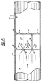
- FIG. 1 shows an apparatus according to the present invention.
- FIG 1 shows a reactor comprising a vessel 2 in the form of an open-ended cylinder. There is a baffle 4 in the vessel 2 and a plurality of first openings 6 in the baffle 4. Through each of these openings 6, a liquid 8, passing through the vessel 2, passes as a jet 10. The openings 6 are arranged sufficiently close to allow impingement of the jets 10, as schematically illustrated by the arrows 12 in Figure 1.
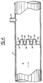
- FIG 2 shows the presence of a second baffle 14, spaced downstream from the first baffle 4.
- the second openings 16 are arranged so that the first and second openings 6 and 16 are not aligned.
- the jets 10 from the first openings impinge on the second baffle 14 as shown by the arrows 18 in Figure 2.
- the first and second openings 6 and 16 are both arranged to direct the jets 10 longitudinally of the apparatus.
- the first and second baffles 4 and 14 extend transversely of the vessel 2.
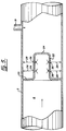
- Figure 3 illustrates an embodiment of the invention in which the baffle 20 comprises an annulus extending inwardly from the periphery of the vessel 2.
- a cylinder 22 extends longitudinally of the vessel 2, from the inner periphery of the annular baffle 20, to terminate in a closure 24 that is parallel to the annular baffle 20.
- Openings 26 are formed in the cylinder 22 so that jets 28 are directed by the openings 26 transverse of the vessel 2.
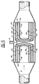
- Figure 5 illustrates an apparatus in which there is a plurality of generally coaxial cylinders 38, 40 and 42, each extending from an annular wall 44 extending from the periphery of vessel 2. Openings 44, 48 and 50 are arranged so that the liquid 8 flowing through an opening in an inner cylinder impinges on the wall of an outer cylinder before it can pass through openings in that outer cylinder.
- Figure 5 also illustrates a particular embodiment of the invention in which there are opposed cylinders.
- Figure 5 also shows cylinders 52, 54 and 56 extending from annular wall 58 towards wall 44. Openings 60, 62 and 64 are formed in cylinders 52, 54 and 56.
- FIG. 6 illustrates an embodiment of the invention in which baffles 66 are formed as generally concentric spheres 68, 70 and 72 each having inlet openings 74 and outlet openings 76 arranged so that liquid flowing in the vessel 2 must pass through the inlets 74, to the inner spheres 68, then outwardly.
- Reactants can be added to the embodiment of Figure 6 through inlet 19.
- An inlet system that uses a multiplicity of pipes distributed radially around reactor vessel 2 may be also be used.
- the location of the inlet pipes 19 may also be between stages of the concentric spheres, as shown in Figure 7.
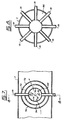
- Figure 8 shows a sectional view through the multiple delivery pipes 19 to demonstrate the arrangement of the pipes through the vessel walls and into the concentric spheres.
- the number and size of the inlet pipes 19 are arranged to ensure a very high velocity jet, with very small droplets entering the reactor.
- Figure 9 illustrates an embodiment of the invention resembling that of Figure 7 and common reference numerals are used where appropriate. However, Figure 9 also shows the use of semi-spherical baffles 78 arranged concentrically around the sphere 68.
- the sphere 68 on the left of Figure 9 has two semi-spherical baffles. On the right of Figure 9 there are two spherical baffles 68 and 70 and one semi-spherical baffle 78, downstream of the pair of spherical baffles 68 and 70.
- Figure 10 also shows the relationship of the embodiment of Figure 9 to the embodiment of Figure 7 in showing multiple inlet pipes 19 extending through the vessel walls and into the sphere 68.
- the local velocity of each stage can be made sufficiently high to create conditions necessary for a nitration reaction between an aromatic hydrocarbon and mixed acid in the liquid 8 to take place independently from the bulk velocities of the reactants passing through the apparatus.
- the proportions of the apparatus can be adjusted, using simple experimental techniques, to achieve a wide range of intensive agitation and residence time.
- the apparatus can be used either as a single unit or as a number of units connected in series or in conjunction with one or more continuously stirred tank reactors.
- the apparatus of the invention is immediately of use in the adiabatic mononitration of benzene because of the large scale manufacture of this product.
- the invention can also be used in the nitration of other aromatic hydrocarbons or halogen substituted aromatic hydrocarbons.
- the particular benefit provided by the present invention is the degree of agitation that is available. This ensures that the reaction rate and conversion efficiency of the reactor are high.
- the desired high agitation is accomplished by causing the jets containing the liquid 8 of aromatic hydrocarbon and mixed acids to be directed towards each other so as to provide varying degrees of impingement of the jets.
- This impingement, or interplay, of the jet produces high shear rates in the liquid, much higher for example than provided by propeller blades in a conventional stirred tank reactor or than of the shearing rates in a static mixer reactor.
- a certain portion of the jet streams will directly impinge so as to bring droplets of the dispersed phase into direct contact and further enhance the reaction.
- the direct impingement of the jets, along with the relative shear between the jets will produce a constant supply of fresh interface between the reacting components, thereby enhancing the reaction rate and overall conversion efficiency of the reactor.
- An additional benefit provided by the present invention is the ability to add reactants in a high velocity jet directly into a region of high-intensity mixing as shown by the inlet system of Figures 7 and 8.
- the high velocity produces a jet of small droplets having a high surface area to mass ratio, thereby promoting the overall conversion of the reactants.
- the jets are turned so that they impinge on the wall of the reactor.
- the impingement, shearing and mixing of the components is further enhanced by the requirement of the fluid to turn back into the main fluid direction, as shown by the arrows.
- Such an arrangement can also be repeated in stages to the desired degree of reaction.
- the multiplicity of lateral jets ensures that some of the liquid jets will impinge directly on each other, achieving the highest possible degree of agitation and therefore reaction rate.
- the arrangement of annular walls and cylinders shown in Figure 4 can be repeated downstream for further conversion, if required. Further reactants can be added through inlet 19 prior to each stage as discussed above for Figure 2.
- Figures 1 to 4 show the flow direction to be axial, but the same principles can also be used if the flow arrangement be radial as shown by the cylindrical arrangement of Figure 5, and the spherical arrangement of Figure 6.
- the flow issues outwardly through a series of cylinders.
- the successive outward cylinders are preferably arranged so that the openings are not in line, producing the maximum benefit of reaction as discussed for Figure 2.
- the same arrangement can be used equally with the flow passing radially inwardly through the cylindrical shells.
- reactants may be added between the two stages through inlet 19.
- the first stage is defined by cylinders 38, 40 and 42 and the second by cylinders 52, 54 and 56. Again this reactant addition between stages improves conversion.
- the reactants are introduced directly between the concentric spheres shown through a plurality of inlet pipes 19 arranged radially about vessel 2.
- the size and number of the inlets is chosen appropriately so that the reactant jet velocity is very high. This promotes the formation of small droplets of reactant which leads to high overall reaction rates and high conversion efficiency.
- Figures 9 and 10 show that hemispheres may be used to achieve the same effect as spheres. Hemispheres may be arranged in any combination or number on the upstream or the downstream side of the spheres. The preferred arrangement depends on the degree of reaction desired and would be determined for any particular set of reaction conditions by routine experiment.
- Figure 10 shows that the arrangement that includes inlet pipes is also compatible with the semi-spherical arrangement shown in Figure 9.
- the vessels 2 can be cylinders of a diameter within the range 6 to 12 inches.
- the openings 6, 16, 26 and 32 may have a diameter of about 1/2 inch. They are symmetrically arranged in walls 4 and 14.
- Flow rates can, for example, be in the range of 100 to 800 U.S. gallons per minute.
- the end pipes shown may, for example, have diameters of about 8 inches.
- the vessels 2 have, for example, diameters of about 12 inches.
- Openings 60, 62, 64, 74 and 76 have diameters, for example, in the range 1/4 to 1/2 inch.
- the inlet pipes 19 may be 1/16 to 5/16 inch with any number of such inlets, for example, 32, disposed radially about the reactor vessel. This embodiment could be used, for example, if only the aromatic hydrocarbon is being added through the inlets.
- the apparatus may be made of glass lined steel, as in the prior art, but preferably are made from zirconium or tantalum or any suitable corrosion-resistant material.
Landscapes
- Chemical & Material Sciences (AREA)
- Chemical Kinetics & Catalysis (AREA)
- Dispersion Chemistry (AREA)
- Organic Chemistry (AREA)
- Organic Low-Molecular-Weight Compounds And Preparation Thereof (AREA)
- Physical Or Chemical Processes And Apparatus (AREA)
- Vibration Dampers (AREA)
Priority Applications (5)
| Application Number | Priority Date | Filing Date | Title |
|---|---|---|---|
| US07/405,930 US4994242A (en) | 1988-08-15 | 1989-09-12 | Jet impingement reactor |
| DE69025615T DE69025615T2 (de) | 1988-08-15 | 1990-12-05 | Jetaufprallreaktor |
| EP90403456A EP0489211B1 (fr) | 1988-08-15 | 1990-12-05 | Réacteur à choc de jets |
| AT90403456T ATE134531T1 (de) | 1988-08-15 | 1990-12-05 | Jetaufprallreaktor |
| ES90403456T ES2085342T3 (es) | 1988-08-15 | 1990-12-05 | Reactor de choque de chorros. |
Applications Claiming Priority (2)
| Application Number | Priority Date | Filing Date | Title |
|---|---|---|---|
| US23233988A | 1988-08-15 | 1988-08-15 | |
| EP90403456A EP0489211B1 (fr) | 1988-08-15 | 1990-12-05 | Réacteur à choc de jets |
Publications (2)
| Publication Number | Publication Date |
|---|---|
| EP0489211A1 true EP0489211A1 (fr) | 1992-06-10 |
| EP0489211B1 EP0489211B1 (fr) | 1996-02-28 |
Family
ID=26925895
Family Applications (1)
| Application Number | Title | Priority Date | Filing Date |
|---|---|---|---|
| EP90403456A Expired - Lifetime EP0489211B1 (fr) | 1988-08-15 | 1990-12-05 | Réacteur à choc de jets |
Country Status (5)
| Country | Link |
|---|---|
| US (1) | US4994242A (fr) |
| EP (1) | EP0489211B1 (fr) |
| AT (1) | ATE134531T1 (fr) |
| DE (1) | DE69025615T2 (fr) |
| ES (1) | ES2085342T3 (fr) |
Cited By (22)
| Publication number | Priority date | Publication date | Assignee | Title |
|---|---|---|---|---|
| WO1995002448A1 (fr) * | 1993-07-14 | 1995-01-26 | Sinvent A/S | Dispositif servant a melanger les elements d'un flux de liquide |
| DE4433439A1 (de) * | 1994-09-20 | 1996-03-21 | Kernforschungsz Karlsruhe | Verfahren zur Durchführung chemischer Reaktionen mittels Mikrostruktur-Mischung |
| WO1998011983A1 (fr) * | 1996-09-19 | 1998-03-26 | Oleg Vyacheslavovich Kozyuk | Procede permettant de modifier la composition qualitative et quantitative d'un melange d'hydrocarbures liquides, base sur les effets de la cavitation |
| US5733577A (en) * | 1994-06-14 | 1998-03-31 | Fuisz Technologies Ltd. | Delivery of controlled-release system (s) |
| US5931771A (en) * | 1997-12-24 | 1999-08-03 | Kozyuk; Oleg V. | Method and apparatus for producing ultra-thin emulsions and dispersions |
| US5937906A (en) * | 1997-05-06 | 1999-08-17 | Kozyuk; Oleg V. | Method and apparatus for conducting sonochemical reactions and processes using hydrodynamic cavitation |
| EP0947239A3 (fr) * | 1998-03-27 | 2000-07-12 | Bayer Ag | Mélangeur statique |
| EP0947238A3 (fr) * | 1998-03-30 | 2000-07-19 | Innovative Engineering Solutions, INC. | Dispositif permettant d'oxyder et d'éliminer des matières dans un courant de gaz dangereux |
| WO2001064333A3 (fr) * | 2000-03-02 | 2002-02-21 | Dow Chemical Co | Reacteur tubulaire, procede de realisation de reactions multiphase liquide/liquide dans un reacteur tubulaire, et procede de nitration cyclique de composes aromatiques dans un reacteur tubulaire |
| US6365555B1 (en) * | 1999-10-25 | 2002-04-02 | Worcester Polytechnic Institute | Method of preparing metal containing compounds using hydrodynamic cavitation |
| DE102004038555B3 (de) * | 2004-08-06 | 2005-08-04 | Plinke Gmbh | Modularer Mikroreaktor zur Nitrierung mit Mischsäure |
| EP1634640A3 (fr) * | 2004-09-10 | 2007-03-28 | M-Il.L.C., | Dispositif et procédé pour l'homogénéisation de deux ou plusieurs liquides avec des densités différentes |
| WO2008071683A1 (fr) * | 2006-12-13 | 2008-06-19 | Emitec Gesellschaft Für Emissionstechnologie | Distributeur de flux pour un système de gaz d'échappement |
| EP2168942A1 (fr) | 2008-09-24 | 2010-03-31 | Bayer MaterialScience AG | Procédé destiné à la fabrication continue de nitrobenzène |
| DE102009005324A1 (de) | 2009-01-16 | 2010-07-22 | Plinke Gmbh | Verfahren zur adiabatischen Nitrierung von Benzol |
| EP2158180A4 (fr) * | 2007-06-27 | 2011-11-23 | H R D Corp | Système et procédé de production de nitrobenzène |
| WO2012160072A1 (fr) | 2011-05-24 | 2012-11-29 | Basf Se | Procédé de production de polyisocyanates à partir de biomasse |
| US8697913B2 (en) | 2009-06-17 | 2014-04-15 | Huntsman International Llc | Chemical installation |
| US8827544B2 (en) | 2007-03-15 | 2014-09-09 | Dow Global Technologies Llc | Mixer for continuous flow reactor, continuous flow reactor, method of forming such a mixer, and method of operating such a reactor |
| US8933262B2 (en) | 2011-05-24 | 2015-01-13 | Basf Se | Process for preparing polyisocyanates from biomass |
| WO2018141451A1 (fr) | 2017-02-03 | 2018-08-09 | Josef Meissner Gmbh & Co. Kg | Procédé et installation de nitruration adiabatique de composés aromatiques |
| WO2022106041A1 (fr) * | 2020-11-23 | 2022-05-27 | Wacker Chemie Ag | Procédé de préparation de dispersions polymères aqueuses dans un réacteur tubulaire |
Families Citing this family (23)
| Publication number | Priority date | Publication date | Assignee | Title |
|---|---|---|---|---|
| US5246673A (en) * | 1988-12-21 | 1993-09-21 | Troy Investments Inc. | Delta singlet oxygen continuous reactor |
| US5313009A (en) * | 1990-01-04 | 1994-05-17 | Nrm International Technologies C.V. | Nitration process |
| US5333952A (en) * | 1993-08-17 | 1994-08-02 | Perdue John L | Chemical mixing chamber |
| DE4437047A1 (de) | 1994-10-17 | 1996-04-18 | Bayer Ag | Verfahren zur Dinitrierung von aromatischen Verbindungen |
| DE19604289C2 (de) * | 1996-02-07 | 1998-04-23 | Danfoss As | Mikromischer |
| US5743638A (en) * | 1996-07-30 | 1998-04-28 | Q-Jet, Dsi | Dual control mixing jet cooker |
| ES2201390T3 (es) * | 1997-11-13 | 2004-03-16 | Haldor Topsoe A/S | Dispositivo de mezcla y un canal de paso de escape con este dispositivo de mezcla. |
| US6849189B2 (en) * | 2002-10-28 | 2005-02-01 | Mote Marine Laboratory | Horizontal reaction chamber comprised of nested, concentric tubes for use in water purification |
| US20060153754A1 (en) * | 2004-10-26 | 2006-07-13 | Hauptmann Edward G | Dispersion-intensified, coalescence-intensified chemical reactor and method |
| EP2014641A3 (fr) * | 2007-06-06 | 2009-03-18 | Huntsman International Llc | Processus de préparation de mélanges de diisocyanates de diphénylméthane et de polyisocyanates de polyméthylène de polyphényle |
| DE102007059513A1 (de) | 2007-12-11 | 2009-06-18 | Bayer Materialscience Ag | Verfahren zur Herstellung von Nitrobenzol durch adiabate Nitrierung |
| JP5332916B2 (ja) * | 2009-06-03 | 2013-11-06 | 株式会社デンソー | 炭化珪素単結晶の製造装置 |
| DE102010006984A1 (de) | 2010-02-05 | 2011-08-11 | Bayer MaterialScience AG, 51373 | Verfahren zur kontinuierlichen Herstellung von Nitrobenzol |
| US9115048B2 (en) | 2011-05-19 | 2015-08-25 | Josef Meissner Gmbh & Co. Kg | Method and apparatus for purifying nitration products |
| US10293309B2 (en) * | 2013-06-13 | 2019-05-21 | Sigma-Technology Inc. | Method, a bubble generating nozzle, and an apparatus for generating micro-nano bubbles |
| JP6403528B2 (ja) * | 2014-10-03 | 2018-10-10 | 旭有機材株式会社 | 流体混合器および流体混合器を用いた装置 |
| US9885375B2 (en) * | 2015-02-18 | 2018-02-06 | Badger Meter, Inc. | Flow conditioner |
| CA3001460C (fr) | 2015-10-14 | 2023-04-04 | Oleg Kozyuk | Procede permettant de reduire les pertes d'huile neutre lors d'une etape de neutralisation |
| US20170362987A1 (en) * | 2016-06-20 | 2017-12-21 | Electro-Motive Diesel | Engine system having mixing mechanism for exhaust and injected fluid and engine exhaust treatment strategy |
| CN112469501A (zh) | 2018-07-24 | 2021-03-09 | 诺拉姆国际公司 | 硝化反应器和方法 |
| GB201818709D0 (en) * | 2018-11-16 | 2019-01-02 | Fujifilm Diosynth Biotechnologies Uk Ltd | Mixer |
| WO2021252715A1 (fr) * | 2020-06-10 | 2021-12-16 | The Johns Hopkins University | Mélangeur à jet d'impact confiné axisymétrique |
| WO2024003050A1 (fr) | 2022-06-28 | 2024-01-04 | Basf Se | Procédé de production de nitrobenzène |
Citations (5)
| Publication number | Priority date | Publication date | Assignee | Title |
|---|---|---|---|---|
| US1698432A (en) * | 1926-01-08 | 1929-01-08 | Standard Oil Co | Orifice mixer |
| DE1039049B (de) * | 1951-11-06 | 1958-09-18 | Nitroglycerin Ab | Verfahren zur Herstellung von Salpetersaeureestern und organischen Nitroverbindungen |
| US4043539A (en) * | 1975-03-28 | 1977-08-23 | Texaco Inc. | Method and apparatus for static type fluid mixing |
| US4136976A (en) * | 1977-05-23 | 1979-01-30 | Nalco Chemical Company | Static mixing device |
| US4596699A (en) * | 1978-05-02 | 1986-06-24 | Societe Nationale Elf Aquitaine (Production) | Apparatus for burning hydrogen sulphide |
Family Cites Families (7)
| Publication number | Priority date | Publication date | Assignee | Title |
|---|---|---|---|---|
| US4208136A (en) * | 1978-12-01 | 1980-06-17 | Komax Systems, Inc. | Static mixing apparatus |
| IT1128825B (it) * | 1980-06-27 | 1986-06-04 | Fiat Ricerche | Dispositivo di miscelazione statico atto a miscelare omogeneamente due o piu componenti allo stato liquido o semiliquido |
| US4398563A (en) * | 1981-09-28 | 1983-08-16 | Vacco Industries | Multi-tube flow restrictor |
| NL8303350A (nl) * | 1982-11-06 | 1984-06-01 | Kernforschungsz Karlsruhe | Statische menger. |
| US4669890A (en) * | 1985-03-25 | 1987-06-02 | Uop Inc. | Mixing device for vertical flow fluid-solid contacting |
| US4647212A (en) * | 1986-03-11 | 1987-03-03 | Act Laboratories, Inc. | Continuous, static mixing apparatus |
| US4786185A (en) * | 1988-02-29 | 1988-11-22 | Phillips Petroleum Company | Apparatus and method for affecting the flow paths of fluid flowing in a pipe |
-
1989
- 1989-09-12 US US07/405,930 patent/US4994242A/en not_active Expired - Lifetime
-
1990
- 1990-12-05 AT AT90403456T patent/ATE134531T1/de not_active IP Right Cessation
- 1990-12-05 DE DE69025615T patent/DE69025615T2/de not_active Expired - Lifetime
- 1990-12-05 EP EP90403456A patent/EP0489211B1/fr not_active Expired - Lifetime
- 1990-12-05 ES ES90403456T patent/ES2085342T3/es not_active Expired - Lifetime
Patent Citations (5)
| Publication number | Priority date | Publication date | Assignee | Title |
|---|---|---|---|---|
| US1698432A (en) * | 1926-01-08 | 1929-01-08 | Standard Oil Co | Orifice mixer |
| DE1039049B (de) * | 1951-11-06 | 1958-09-18 | Nitroglycerin Ab | Verfahren zur Herstellung von Salpetersaeureestern und organischen Nitroverbindungen |
| US4043539A (en) * | 1975-03-28 | 1977-08-23 | Texaco Inc. | Method and apparatus for static type fluid mixing |
| US4136976A (en) * | 1977-05-23 | 1979-01-30 | Nalco Chemical Company | Static mixing device |
| US4596699A (en) * | 1978-05-02 | 1986-06-24 | Societe Nationale Elf Aquitaine (Production) | Apparatus for burning hydrogen sulphide |
Non-Patent Citations (1)
| Title |
|---|
| PATENT ABSTRACTS OF JAPAN, vol. 7, no. 100 (C-164)[1245], 28th April 1983; & JP-A-58 27 626 (NITSUKOOAAMUZU K.K.) 18-02-1983 * |
Cited By (35)
| Publication number | Priority date | Publication date | Assignee | Title |
|---|---|---|---|---|
| CN1047740C (zh) * | 1993-07-14 | 1999-12-29 | 新文特公司 | 流体流中各成分的混合装置 |
| WO1995002448A1 (fr) * | 1993-07-14 | 1995-01-26 | Sinvent A/S | Dispositif servant a melanger les elements d'un flux de liquide |
| US5733577A (en) * | 1994-06-14 | 1998-03-31 | Fuisz Technologies Ltd. | Delivery of controlled-release system (s) |
| DE4433439A1 (de) * | 1994-09-20 | 1996-03-21 | Kernforschungsz Karlsruhe | Verfahren zur Durchführung chemischer Reaktionen mittels Mikrostruktur-Mischung |
| WO1998011983A1 (fr) * | 1996-09-19 | 1998-03-26 | Oleg Vyacheslavovich Kozyuk | Procede permettant de modifier la composition qualitative et quantitative d'un melange d'hydrocarbures liquides, base sur les effets de la cavitation |
| US5937906A (en) * | 1997-05-06 | 1999-08-17 | Kozyuk; Oleg V. | Method and apparatus for conducting sonochemical reactions and processes using hydrodynamic cavitation |
| US6035897A (en) * | 1997-05-06 | 2000-03-14 | Kozyuk; Oleg Vyacheslavovich | Method and apparatus for conducting sonochemical reactions and processes using hydrodynamic cavitation |
| US5931771A (en) * | 1997-12-24 | 1999-08-03 | Kozyuk; Oleg V. | Method and apparatus for producing ultra-thin emulsions and dispersions |
| EP0947239A3 (fr) * | 1998-03-27 | 2000-07-12 | Bayer Ag | Mélangeur statique |
| US7390121B2 (en) | 1998-03-27 | 2008-06-24 | Bayer Aktiengesellschaft | Static mixer module |
| EP0947238A3 (fr) * | 1998-03-30 | 2000-07-19 | Innovative Engineering Solutions, INC. | Dispositif permettant d'oxyder et d'éliminer des matières dans un courant de gaz dangereux |
| US6869586B1 (en) | 1999-10-25 | 2005-03-22 | Five Star Technologies, Inc. | Method of preparing metal containing compounds using hydrodynamic cavitation |
| US6365555B1 (en) * | 1999-10-25 | 2002-04-02 | Worcester Polytechnic Institute | Method of preparing metal containing compounds using hydrodynamic cavitation |
| US7303732B2 (en) | 2000-03-02 | 2007-12-04 | Dow Global Technologies Inc. | Tubular reactor having static mixing elements separated by coalescing zones |
| US6506949B2 (en) | 2000-03-02 | 2003-01-14 | Dow Global Technologies, Inc. | Process for ring nitrating aromatic compounds in a tubular reactor having static mixing elements separated by coalescing zones |
| WO2001064333A3 (fr) * | 2000-03-02 | 2002-02-21 | Dow Chemical Co | Reacteur tubulaire, procede de realisation de reactions multiphase liquide/liquide dans un reacteur tubulaire, et procede de nitration cyclique de composes aromatiques dans un reacteur tubulaire |
| DE102004038555B3 (de) * | 2004-08-06 | 2005-08-04 | Plinke Gmbh | Modularer Mikroreaktor zur Nitrierung mit Mischsäure |
| US8702299B2 (en) | 2004-09-10 | 2014-04-22 | M-I L.L.C. | Apparatus and method for homogenizing two or more fluids of different densities |
| EP1634640A3 (fr) * | 2004-09-10 | 2007-03-28 | M-Il.L.C., | Dispositif et procédé pour l'homogénéisation de deux ou plusieurs liquides avec des densités différentes |
| US8079751B2 (en) | 2004-09-10 | 2011-12-20 | M-I L.L.C. | Apparatus for homogenizing two or more fluids of different densities |
| WO2008071683A1 (fr) * | 2006-12-13 | 2008-06-19 | Emitec Gesellschaft Für Emissionstechnologie | Distributeur de flux pour un système de gaz d'échappement |
| US8827544B2 (en) | 2007-03-15 | 2014-09-09 | Dow Global Technologies Llc | Mixer for continuous flow reactor, continuous flow reactor, method of forming such a mixer, and method of operating such a reactor |
| EP2158180A4 (fr) * | 2007-06-27 | 2011-11-23 | H R D Corp | Système et procédé de production de nitrobenzène |
| EP2168942A1 (fr) | 2008-09-24 | 2010-03-31 | Bayer MaterialScience AG | Procédé destiné à la fabrication continue de nitrobenzène |
| DE102009005324A1 (de) | 2009-01-16 | 2010-07-22 | Plinke Gmbh | Verfahren zur adiabatischen Nitrierung von Benzol |
| US8697913B2 (en) | 2009-06-17 | 2014-04-15 | Huntsman International Llc | Chemical installation |
| US9102586B2 (en) | 2009-06-17 | 2015-08-11 | Huntsman International Llc | Method for producing DADPM |
| WO2012160072A1 (fr) | 2011-05-24 | 2012-11-29 | Basf Se | Procédé de production de polyisocyanates à partir de biomasse |
| US8933262B2 (en) | 2011-05-24 | 2015-01-13 | Basf Se | Process for preparing polyisocyanates from biomass |
| WO2018141451A1 (fr) | 2017-02-03 | 2018-08-09 | Josef Meissner Gmbh & Co. Kg | Procédé et installation de nitruration adiabatique de composés aromatiques |
| DE102017110084A1 (de) | 2017-02-03 | 2018-08-09 | Josef Meissner Gmbh & Co. Kg | Verfahren und Anlage zur adiabatischen Nitrierung von Aromaten |
| DE102017110084B4 (de) | 2017-02-03 | 2019-07-04 | Josef Meissner Gmbh & Co. Kg | Verfahren und Anlage zur adiabatischen Nitrierung von Aromaten |
| DE102017110084C5 (de) | 2017-02-03 | 2026-02-26 | Josef Meissner Gmbh & Co. Kg | Verwendungen von Nitroaromaten in der adiabatischen Nitrierung von Aromaten |
| WO2022106041A1 (fr) * | 2020-11-23 | 2022-05-27 | Wacker Chemie Ag | Procédé de préparation de dispersions polymères aqueuses dans un réacteur tubulaire |
| US12565553B2 (en) | 2020-11-23 | 2026-03-03 | Wacker Chemie Ag | Process for preparing aqueous polymer dispersions in a tubular reactor |
Also Published As
| Publication number | Publication date |
|---|---|
| ES2085342T3 (es) | 1996-06-01 |
| EP0489211B1 (fr) | 1996-02-28 |
| ATE134531T1 (de) | 1996-03-15 |
| DE69025615T2 (de) | 1996-09-12 |
| US4994242A (en) | 1991-02-19 |
| DE69025615D1 (de) | 1996-04-04 |
Similar Documents
| Publication | Publication Date | Title |
|---|---|---|
| EP0489211B1 (fr) | Réacteur à choc de jets | |
| US6562247B2 (en) | Process for conducting liquid/liquid multiphase reactions in a tubular reactor having static mixing elements separated by coalescing zones | |
| US5616818A (en) | Process for the polynitration of aromatic compounds | |
| US4973770A (en) | Manufacture of organic nitro compounds | |
| EP2043770B1 (fr) | Appareil et procédé de mélange | |
| US20130150618A1 (en) | Mixing apparatus | |
| SE439885B (sv) | Sett for blandning av atminstone tva fluider samt plattblandare herfor | |
| CN110237794B (zh) | 超声强化射流式反应器 | |
| NZ267029A (en) | Passive reactor; multiphase, staged, reactor has stages defining a flow path for substances to be reacted, the flow path being curved | |
| US7922981B2 (en) | Dispersion-intensified, coalescence-intensified chemical reactor and method | |
| CN113332947A (zh) | 一种高流量比快速混合器及利用上述混合器的环形反应系统 | |
| US3752653A (en) | Continuous-flow agitated reactor | |
| EP2158180B1 (fr) | Système et procédé de production de nitrobenzène | |
| CA2036174C (fr) | Reacteur a jets convergents | |
| US20140072481A1 (en) | Catalytic static mixing reactor | |
| EP3826763B1 (fr) | Réacteur et procédé de nitration | |
| GB1558751A (en) | Apparatus and process for the continuous nitration of cellulose | |
| EP1501626B1 (fr) | Dispositif et procede de creation de cavitation hydrodynamique dans des fluides | |
| PT96782B (pt) | Aparelho para proporcionar uma reaccao em fase liquida e processo para a conducao de uma reaccao entre pelo menos dois reagentes na fase liquida | |
| RU2753756C1 (ru) | Аппарат для проведения массообменных и реакционных процессов в однофазных и многофазных средах | |
| RU2082486C1 (ru) | Смеситель-реактор | |
| SU1294369A1 (ru) | Реактор | |
| RU2241531C1 (ru) | Смеситель | |
| SU1678436A1 (ru) | Химический реактор | |
| SU975046A1 (ru) | Статический лопастной смеситель |
Legal Events
| Date | Code | Title | Description |
|---|---|---|---|
| PUAI | Public reference made under article 153(3) epc to a published international application that has entered the european phase |
Free format text: ORIGINAL CODE: 0009012 |
|
| AK | Designated contracting states |
Kind code of ref document: A1 Designated state(s): AT BE CH DE DK ES FR GB GR IT LI LU NL SE |
|
| 17P | Request for examination filed |
Effective date: 19921202 |
|
| RAP1 | Party data changed (applicant data changed or rights of an application transferred) |
Owner name: NRM INTERNATIONAL TECHNOLOGIES C.V. |
|
| 17Q | First examination report despatched |
Effective date: 19940113 |
|
| GRAA | (expected) grant |
Free format text: ORIGINAL CODE: 0009210 |
|
| AK | Designated contracting states |
Kind code of ref document: B1 Designated state(s): AT BE CH DE DK ES FR GB GR IT LI LU NL SE |
|
| PG25 | Lapsed in a contracting state [announced via postgrant information from national office to epo] |
Ref country code: AT Effective date: 19960228 Ref country code: DK Effective date: 19960228 Ref country code: LI Effective date: 19960228 Ref country code: GR Free format text: LAPSE BECAUSE OF FAILURE TO SUBMIT A TRANSLATION OF THE DESCRIPTION OR TO PAY THE FEE WITHIN THE PRESCRIBED TIME-LIMIT Effective date: 19960228 Ref country code: CH Effective date: 19960228 |
|
| REF | Corresponds to: |
Ref document number: 134531 Country of ref document: AT Date of ref document: 19960315 Kind code of ref document: T |
|
| REF | Corresponds to: |
Ref document number: 69025615 Country of ref document: DE Date of ref document: 19960404 |
|
| ET | Fr: translation filed | ||
| ITF | It: translation for a ep patent filed | ||
| PG25 | Lapsed in a contracting state [announced via postgrant information from national office to epo] |
Ref country code: SE Effective date: 19960531 |
|
| REG | Reference to a national code |
Ref country code: ES Ref legal event code: FG2A Ref document number: 2085342 Country of ref document: ES Kind code of ref document: T3 |
|
| REG | Reference to a national code |
Ref country code: CH Ref legal event code: PL |
|
| PG25 | Lapsed in a contracting state [announced via postgrant information from national office to epo] |
Ref country code: LU Free format text: LAPSE BECAUSE OF NON-PAYMENT OF DUE FEES Effective date: 19961231 |
|
| PLBE | No opposition filed within time limit |
Free format text: ORIGINAL CODE: 0009261 |
|
| STAA | Information on the status of an ep patent application or granted ep patent |
Free format text: STATUS: NO OPPOSITION FILED WITHIN TIME LIMIT |
|
| 26N | No opposition filed | ||
| REG | Reference to a national code |
Ref country code: FR Ref legal event code: CA |
|
| REG | Reference to a national code |
Ref country code: GB Ref legal event code: IF02 |
|
| NLS | Nl: assignments of ep-patents |
Owner name: NORAM INTERNATIONAL LIMITED Effective date: 20090211 |
|
| PGFP | Annual fee paid to national office [announced via postgrant information from national office to epo] |
Ref country code: BE Payment date: 20090819 Year of fee payment: 20 Ref country code: NL Payment date: 20091222 Year of fee payment: 20 |
|
| PGFP | Annual fee paid to national office [announced via postgrant information from national office to epo] |
Ref country code: IT Payment date: 20091215 Year of fee payment: 20 Ref country code: GB Payment date: 20091020 Year of fee payment: 20 Ref country code: ES Payment date: 20100201 Year of fee payment: 20 |
|
| PGFP | Annual fee paid to national office [announced via postgrant information from national office to epo] |
Ref country code: DE Payment date: 20091208 Year of fee payment: 20 |
|
| REG | Reference to a national code |
Ref country code: NL Ref legal event code: V4 Effective date: 20101205 |
|
| REG | Reference to a national code |
Ref country code: GB Ref legal event code: PE20 Expiry date: 20101204 |
|
| BE20 | Be: patent expired |
Owner name: *NRM INTERNATIONAL TECHNOLOGIES C.V. Effective date: 20101205 |
|
| PG25 | Lapsed in a contracting state [announced via postgrant information from national office to epo] |
Ref country code: NL Free format text: LAPSE BECAUSE OF EXPIRATION OF PROTECTION Effective date: 20101205 Ref country code: GB Free format text: LAPSE BECAUSE OF EXPIRATION OF PROTECTION Effective date: 20101204 |
|
| PGFP | Annual fee paid to national office [announced via postgrant information from national office to epo] |
Ref country code: FR Payment date: 20090914 Year of fee payment: 20 |
|
| PG25 | Lapsed in a contracting state [announced via postgrant information from national office to epo] |
Ref country code: DE Free format text: LAPSE BECAUSE OF EXPIRATION OF PROTECTION Effective date: 20101205 |
|
| REG | Reference to a national code |
Ref country code: ES Ref legal event code: FD2A Effective date: 20130801 |
|
| PG25 | Lapsed in a contracting state [announced via postgrant information from national office to epo] |
Ref country code: ES Free format text: LAPSE BECAUSE OF EXPIRATION OF PROTECTION Effective date: 20101206 |