EP0489377A1 - Ressort hélicoidal du type incliné chargé radialement - Google Patents
Ressort hélicoidal du type incliné chargé radialement Download PDFInfo
- Publication number
- EP0489377A1 EP0489377A1 EP91120636A EP91120636A EP0489377A1 EP 0489377 A1 EP0489377 A1 EP 0489377A1 EP 91120636 A EP91120636 A EP 91120636A EP 91120636 A EP91120636 A EP 91120636A EP 0489377 A1 EP0489377 A1 EP 0489377A1
- Authority
- EP
- European Patent Office
- Prior art keywords
- coil spring
- radial
- canted coil
- spring
- garter
- Prior art date
- Legal status (The legal status is an assumption and is not a legal conclusion. Google has not performed a legal analysis and makes no representation as to the accuracy of the status listed.)
- Withdrawn
Links
Images

Classifications
-
- F—MECHANICAL ENGINEERING; LIGHTING; HEATING; WEAPONS; BLASTING
- F16—ENGINEERING ELEMENTS AND UNITS; GENERAL MEASURES FOR PRODUCING AND MAINTAINING EFFECTIVE FUNCTIONING OF MACHINES OR INSTALLATIONS; THERMAL INSULATION IN GENERAL
- F16F—SPRINGS; SHOCK-ABSORBERS; MEANS FOR DAMPING VIBRATION
- F16F1/00—Springs
- F16F1/02—Springs made of steel or other material having low internal friction; Wound, torsion, leaf, cup, ring or the like springs, the material of the spring not being relevant
- F16F1/04—Wound springs
-
- F—MECHANICAL ENGINEERING; LIGHTING; HEATING; WEAPONS; BLASTING
- F16—ENGINEERING ELEMENTS AND UNITS; GENERAL MEASURES FOR PRODUCING AND MAINTAINING EFFECTIVE FUNCTIONING OF MACHINES OR INSTALLATIONS; THERMAL INSULATION IN GENERAL
- F16F—SPRINGS; SHOCK-ABSORBERS; MEANS FOR DAMPING VIBRATION
- F16F1/00—Springs
- F16F1/02—Springs made of steel or other material having low internal friction; Wound, torsion, leaf, cup, ring or the like springs, the material of the spring not being relevant
- F16F1/04—Wound springs
- F16F1/045—Canted-coil springs
-
- F—MECHANICAL ENGINEERING; LIGHTING; HEATING; WEAPONS; BLASTING
- F16—ENGINEERING ELEMENTS AND UNITS; GENERAL MEASURES FOR PRODUCING AND MAINTAINING EFFECTIVE FUNCTIONING OF MACHINES OR INSTALLATIONS; THERMAL INSULATION IN GENERAL
- F16J—PISTONS; CYLINDERS; SEALINGS
- F16J15/00—Sealings
- F16J15/02—Sealings between relatively-stationary surfaces
- F16J15/021—Sealings between relatively-stationary surfaces with elastic packing
- F16J15/022—Sealings between relatively-stationary surfaces with elastic packing characterised by structure or material
- F16J15/024—Sealings between relatively-stationary surfaces with elastic packing characterised by structure or material the packing being locally weakened in order to increase elasticity
- F16J15/025—Sealings between relatively-stationary surfaces with elastic packing characterised by structure or material the packing being locally weakened in order to increase elasticity and with at least one flexible lip
-
- F—MECHANICAL ENGINEERING; LIGHTING; HEATING; WEAPONS; BLASTING
- F16—ENGINEERING ELEMENTS AND UNITS; GENERAL MEASURES FOR PRODUCING AND MAINTAINING EFFECTIVE FUNCTIONING OF MACHINES OR INSTALLATIONS; THERMAL INSULATION IN GENERAL
- F16J—PISTONS; CYLINDERS; SEALINGS
- F16J15/00—Sealings
- F16J15/02—Sealings between relatively-stationary surfaces
- F16J15/06—Sealings between relatively-stationary surfaces with solid packing compressed between sealing surfaces
- F16J15/08—Sealings between relatively-stationary surfaces with solid packing compressed between sealing surfaces with exclusively metal packing
- F16J15/0887—Sealings between relatively-stationary surfaces with solid packing compressed between sealing surfaces with exclusively metal packing the sealing effect being obtained by elastic deformation of the packing
- F16J15/0893—Sealings between relatively-stationary surfaces with solid packing compressed between sealing surfaces with exclusively metal packing the sealing effect being obtained by elastic deformation of the packing the packing having a hollow profile
-
- F—MECHANICAL ENGINEERING; LIGHTING; HEATING; WEAPONS; BLASTING
- F16—ENGINEERING ELEMENTS AND UNITS; GENERAL MEASURES FOR PRODUCING AND MAINTAINING EFFECTIVE FUNCTIONING OF MACHINES OR INSTALLATIONS; THERMAL INSULATION IN GENERAL
- F16J—PISTONS; CYLINDERS; SEALINGS
- F16J15/00—Sealings
- F16J15/16—Sealings between relatively-moving surfaces
- F16J15/34—Sealings between relatively-moving surfaces with slip-ring pressed against a more or less radial face on one member
- F16J15/3436—Pressing means
- F16J15/344—Pressing means the pressing force being applied by means of an elastic ring supporting the slip-ring
Definitions
- the present invention generally relates to canted-coil springs and seals and, more particularly, relates to canted-coil springs retained in a groove with interference between the spring coils and the groove to retain the spring in a selected orientation for subsequent loading of the spring. Orienting the spring for major or minor axis loading enables a specific selected resilient, or load-deflection, characteristic, in response to the subsequent loading of the springs.
- the present invention concerns garter-type spring assemblies best suited for radial loading of the spring.
- the force-deflection characteristics of heretofore available garter-type axially loaded springs have been varied by changing numerous spring parameters, including the wire size, the coil height, the coil spacing, and the front angle, which defines a leading portion of each canted spring coil. While these parameters can be used effectively to tailor the load-deflection characteristics of the spring, they do not either dominate or enable the spring to achieve its total design potential. This was taught in U.S. Patent Nos. 4,826,144 and 4,915,366 to Balsells.
- the selected disposition of the back angle and trailing portions defined thereby provides for the capability of tailoring a garter-type axially resilient coil spring beyond the range of conventional garter-type resilient coil springs heretofore known.
- springs may be formulated with higher load-deflection characteristics. That is, the spring is able to exert a greater force in response to a given deflection than a spring having the same dimensions and wire size with a trailing portion along the inside diameter of the spring.
- these springs can be fabricated from smaller wire and have a closer coil spacing, while still exerting the same force in response to deflection as prior art springs.
- the present invention is related to the discovery of other parameters which can be utilized to design garter-type springs having selected load-deflection characteristics, particularly when radially loaded.
- the spring may be mounted, or contained, in a position wherein it will cant radially along the major axis and radially along the minor axis under application of both a radial and axial force.
- this disclosure of a reinforcement element while in the shape of a spring, is not free to flex or be independently loaded, because it is imbedded in the body of a sealing element so as to be flush with the surface thereof. it is obvious that when so imbedded, this reinforcement element, or spring, is not free to flex or be independently loaded with the load-deflection characteristics that it would have in free space; that is, uninhibited deflection under load.
- the canted-coil spring apparatus in accordance with the present invention generally includes a plurality of coils having a major and minor axis which are canted along a center line defined by an intersection of the major and minor axes.
- the coils are interconnected in a manner forming a garter-type canted coil spring.
- Back angle means is provided for both defining the disposition of a trailing portion of each coil with respect to a line normal to the center line and for determining a radial load-deflection characteristic of the canted-coil spring assembly.
- Front angle means is provided for defining the disposition of a leading portion of each coil with respect to the normal line, with the front angle means being greater than the back angle means.
- Also provided in accordance with the present invention are means for non-invasively supporting the plurality of coils in a preselected orientation suitable for radial loading of the garter-type canted coil spring and for controlling the radial resilient characteristics of the garter-type canted coil spring.
- the means for non-invasively supporting the garter-type resilient coil may include means, defining a groove, for deflecting the spring along the minor axis thereof and enabling the garter-type resilient coil spring to be radially loaded along the major axis thereof.
- the groove may provide means for deflecting the spring along the major axis thereof and enabling the garter-type resilient coil spring to be radially loaded along the major axis thereof.
- the trailing portion may be disposed on an outside diameter of the garter-type resilient canted-coil spring and the leading portion disposed along an inside diameter of the garter-type resilient canted-coil spring and the leading portion disposed along an inside diameter of the garter-type resilient coil spring.
- the trailing portion may be disposed along an inside diameter of the garter-type spring and the leading portion may be disposed along an outside diameter of the garter-type coil spring.
- the back angle is selected to provide a radial load-deflection characteristic in which the load remains relatively constant within a working deflection and, further, the groove means may have a width at most equal to the coil height or in another embodiment in which the groove means may have a width greater than the coil height but less than the coil width.
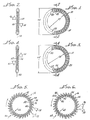
- FIG. 1 through 6 there is shown a number of canted coil spring assemblies 10, 12, 14, 16, in accordance with the present invention, each including a plurality of coils 18, 20, 22, 24, respectively, canted along center lines 28, 30, 32, 34.
- Springs 10 an 12 have the coils 18, 20 interconnected in a manner forming a circular spring having primary load-deflection characteristics along an axial direction of the circular springs 10, 12.
- Spring 10 shown in Figure 1, which has a clockwise canting of coils, has the coils 18 interconnected so that a back angle 38, which defines a trailing portion 40, is along an inside diameter 42 of the spring 10; and a front angle 46, which defines a leading portion 48 of the coil 18, is along an outside diameter 50 he spring 10. See Figure 2.
- the axial spring 12 therein has the coils 20 interconnected in a fashion having a counter-clockwise canting of coils with a back angle 54, defining a trailing portion 56, along inside diameter 58 of the spring 12 and a front angle 60, defining a leading portion 62, along an outside diameter 64 of the spring 12.
- springs 14, 16 having a plurality of coils 20, 24 which are interconnected in a manner forming a circular spring having a primary load-deflection characteristic along a radial direction indicated by the arrows 66, 68.
- the coils are interconnected in a manner for providing a clockwise canting with back angle 72 defining a trailing portion 74 along a top 76 and a front angle 78 defining a leading portion 80 which is disposed along a bottom 82 of the spring 14.
- the spring 16 may have coils 24 interconnected in a manner causing canting of the coils in a counter-clockwise direction with a back angle 88 defining a trailing portion 90 along a bottom 92 of the spring 16 and a front angle 96 defining a leading portion 98 disposed along a top 100 of the spring 16.
- all of the springs 10, 12, 14, 16 may have a generally constant force-deflection characteristic within a working deflection thereof.
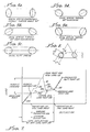
- the load-deflection curve may be constant or show a slight increase, as shown in Figure 7.
- the area between the minimum load point 102 and the maximum load point 104 is known as the working deflection range 106.
- the spring is normally loaded for operation within this rang, as indicated by point 103 for a typical spring utilized in conjunction with seal, gasket, or the like, for sealing purposes.
- a load-deflection curve B showing the characteristics of the spring 10, 12, 14, 16 made in accordance with the present invention, showing a linear load-deflection segment 116 until a peak load point 118 is reached. After the peak point 38, the load decreases with deflection in segment 120. This results in a saddle-type deflection range between the peak point 118 and the butt point 110.
- This type of load-deflection characteristic may have specific advantage for spring seals which are locked in position, such as a groove, with the tension thereof being caused by the spring.
- spring seals which are locked in position, such as a groove, with the tension thereof being caused by the spring.
- changes beyond the working range limits at points 126, 128 cause an abrupt increase in load. This causes the spring seal to be self-centering within a groove, or the like.
- Figure 8 shows, in schematic form, a cross-section of a canted coil spring 10, 12, 14, 16 in accordance with the present invention, with a free axial turn angle ⁇ , a measured coil width, CW, a measured coil height, CH, and a measured spring height H.
- the free turn angle ⁇ may be clockwise (bold lines) or counterclockwise (dashed lines).
- an axially flat spring may be turned up counterclockwise, for example, 30 degrees, as shown in Figure 9b, and 90 degrees as shown in Figure 9a, or turned clockwise as, for example, shown in Figures 9d and 9e, with 30 degree and 60 degree turn angles, respectively.
- the springs are shown with an elliptical shape, other shapes are possible, such as circular or rectangular, depending upon the configuration of the mating parts between which the spring 10, 12, 14, 16 is to be placed.
- the free axial turn angle ⁇ is defined as an angle formed by a generally circular spring forming a cone or an inverted cone, depending on the position of the spring and measuring the angle ⁇ from the horizontal to the intersection through the center line of each cone, or inverted cone.
- the turn angle ⁇ By varying the turn angle ⁇ , different loads can be obtained and the degree of loading depends upon the turn angle ⁇ . That is, the higher the turn angle ⁇ , the higher the force developed, as will be hereinafter demonstrated.
- the force developed upon loading is independent whether the spring is in the cone shape, as shown in Figure 9b, or an inverted cone, as shown in Figure 9c. That is, the springs in 9b and 9c will perform in identical fashion.
- Figs. 10a, 110b, and 10c there is shown positions for springs 200 202 204 in a free, or unloaded, state but suitable for radial loading.
- springs 200 and 202 have an axial turn angle ⁇ of 60° with the spring 200 shown in Fig. 10a being an inverted cone-type and the spring 202 shown in Fig. 10b being of a cone type.
- the axial turn angle referred to throughout this specification is taken in context with rotation of the spring, for example, spring 200 about a center line 206 with the turn angle ⁇ measured from the radius 208, a being, for example, about 60° as shown in Figs. 10a and 10b.
- Fig. 10c shows a radial spring having an axial turn angle approximately 90° with a coil height, CH, measured along a minor axis 210 and a coil width, CW, measured along a major axis 212.
- Fig. 11a shows the spring 200 disposed within a groove 214 having a groove width greater than the coil height, CH, and a groove height, GH, less than the coil width, CW. This provides for a load turn angle ⁇ of about 35°.
- the radial groove 214 positions the spring 200 for a radial loading against a piston, or shaft 224, which results in a deflection 226 of the spring 200.
- spring 200 is shown in a preferred position, i.e., in an inverted cone position using a minimum amount of force.
- the spring 200 could also be assembled in a cone-type position, as shown in Fig. 12a, which would develop substantial higher force.
- the spring may be mounted in a radial groove 230 disposed in a shaft, or piston, 232 loading the spring in a similar manner against a housing 234.
- springs 240 242 244 shown in Figs. 12a, 12b and 12c are similar to those heretofore described in connection with springs 200 202 204, except that turn angle ⁇ is approximately 80° for springs 240 and 242, as shown in Figs. 12a and 12b.
- Spring 242 may be disposed in a radial groove 250 and housing 252 for radial loading by a piston, or shaft, 254.
- the groove width, GW is less than the coil width, CW
- the groove height, GH is less than the coil height, CH.
- the load turn angle ⁇ is about 5°, and the loading occurs generally along the minor axis 260 of the spring 242. This is to be contrasted with the generally major axis 212 loading of the spring 200 as shown in Fig. 11a.
- spring 242 upon assembly of the spring 242 into the radial groove 250, spring 242 will be turned along the major axis of the coil, and in this instance, its turn angle will be relatively small so as to retain the spring 242 in the radial groove 250.
- the turn angle ⁇ is about 80° but can be between 80° and 90°
- An ⁇ turn angle smaller than 80° will make it more difficult to retain the spring 242 into the radial groove 250.
- spring 242 is disposed in a radial groove 270 in a piston, or shaft, 272 for deflection by housing 274.
- the assembly turn angle is about 5° and the groove width, GW, is less than the coil width, CW, and the groove height, GH, is less than the coil height, CH.
- a groove 280 may have a tapered configuration, or a negative angle ⁇ , to improve spring retention therein.
- the radial groove 280 has a width 282 at a bottom 284 thereof greater than a width 286 at an opening 288 thereof through which the spring (not shown in Fig. 14) is inserted for loading by a shaft 290.
Landscapes
- Engineering & Computer Science (AREA)
- General Engineering & Computer Science (AREA)
- Mechanical Engineering (AREA)
- Springs (AREA)
Applications Claiming Priority (2)
| Application Number | Priority Date | Filing Date | Title |
|---|---|---|---|
| US07/620,732 US5139276A (en) | 1988-04-25 | 1990-12-03 | Canted coil spring radially loaded while in a cavity |
| US620732 | 2003-07-16 |
Publications (1)
| Publication Number | Publication Date |
|---|---|
| EP0489377A1 true EP0489377A1 (fr) | 1992-06-10 |
Family
ID=24487158
Family Applications (1)
| Application Number | Title | Priority Date | Filing Date |
|---|---|---|---|
| EP91120636A Withdrawn EP0489377A1 (fr) | 1990-12-03 | 1991-11-30 | Ressort hélicoidal du type incliné chargé radialement |
Country Status (3)
| Country | Link |
|---|---|
| US (1) | US5139276A (fr) |
| EP (1) | EP0489377A1 (fr) |
| JP (1) | JPH04266629A (fr) |
Cited By (1)
| Publication number | Priority date | Publication date | Assignee | Title |
|---|---|---|---|---|
| US10570864B2 (en) | 2015-10-09 | 2020-02-25 | Continental Automotive Gmbh | Fluid-injection device for internal combustion engines |
Families Citing this family (63)
| Publication number | Priority date | Publication date | Assignee | Title |
|---|---|---|---|---|
| US5222429A (en) * | 1992-05-11 | 1993-06-29 | Caterpillar Inc. | Piston assembly for a hydraulic cylinder |
| US5474309A (en) * | 1993-06-11 | 1995-12-12 | Bal Seal Engineering Company, Inc. | Gasket assembly for sealing electromagnetic waves |
| US5560278A (en) * | 1994-10-11 | 1996-10-01 | Caterpillar Inc. | Hydraulic cylinder with an electrical contacting and sealing ring |
| US5540137A (en) * | 1994-10-11 | 1996-07-30 | Caterpillar Inc. | Electrical contacting in electromagnetic wave piston position sensing in a hydraulic cylinder |
| US6186510B1 (en) | 1996-01-30 | 2001-02-13 | Power Packing Company, Inc. | Mechanical contact bearing seal |
| JPH1172130A (ja) * | 1997-07-07 | 1999-03-16 | Bal Seal Eng Co Inc | 長軸に沿って傾けたコイルを備えた径方向用のばね及び軸線方向用のばね |
| US6416330B1 (en) | 2000-07-17 | 2002-07-09 | Cray Inc. | Canted coil spring conductor electrical circuit connector |
| WO2003046392A2 (fr) | 2001-11-21 | 2003-06-05 | Bal Seal Engineering Co., Inc. | Connecteur dote d'un ressort radial |
| US20030204262A1 (en) * | 2002-04-30 | 2003-10-30 | Ferguson Joe William | Quick disconnect orthopaedic trials |
| US7055812B2 (en) * | 2002-09-30 | 2006-06-06 | Bal Seal Engineering Co., Inc. | Canted coil springs various designs |
| US6966802B2 (en) * | 2003-02-11 | 2005-11-22 | Tyco Electroncis Amp Gmbh | Plug connector |
| JP2006518090A (ja) * | 2003-02-18 | 2006-08-03 | バル・シール・エンジニアリング・カンパニー・インコーポレーテッド | バネ保持コネクタ |
| US7198642B2 (en) * | 2003-03-31 | 2007-04-03 | Depuy Products, Inc. | Orthopaedic spacer |
| US7141067B2 (en) * | 2003-03-31 | 2006-11-28 | Depuy Products, Inc. | Intercalary implant |
| US7125423B2 (en) * | 2003-03-31 | 2006-10-24 | Depuy Products, Inc. | Intercalary prosthesis, kit and method |
| US8167285B2 (en) | 2003-06-04 | 2012-05-01 | Bal Seal Engineering Co., Inc. | Spring latching connectors radially and axially mounted |
| US9267526B2 (en) * | 2003-06-04 | 2016-02-23 | Bal Seal Engineering, Inc. | Spring latching connectors |
| US6880863B2 (en) | 2003-06-06 | 2005-04-19 | Delaware Capital Formation, Inc. | Flexible coupling for gas conduits |
| US20050242910A1 (en) * | 2004-04-29 | 2005-11-03 | Balsells Peter J | Contact assembly |
| WO2006044216A2 (fr) * | 2004-10-12 | 2006-04-27 | Bal Seal Engineering Co., Inc. | Dispositif de fermeture a anneau segmente a ressorts |
| US20060228166A1 (en) * | 2005-04-05 | 2006-10-12 | Bal Seal Engineering Co., Inc. | Ball holding, latching and locking applications using radial and axial springs |
| US7758274B2 (en) * | 2006-04-11 | 2010-07-20 | Warsaw Orthopedic, Inc. | Quick attachment apparatus for use in association with orthopedic instrumentation and tools |
| WO2008022014A2 (fr) * | 2006-08-10 | 2008-02-21 | Research Sciences, Llc | Joint d'étanchéité compressible à amplitude étendue et plusieurs éléments |
| US8114024B2 (en) * | 2007-08-20 | 2012-02-14 | Interson Corporation | Seal for a rotating shaft |
| JP2011507162A (ja) | 2007-12-06 | 2011-03-03 | バル・シール・エンジニアリング | インラインコネクタ |
| US8328202B2 (en) | 2007-12-07 | 2012-12-11 | Bal Seal Engineering, Inc. | Seal assembly for high pressure dynamic and static services |
| US9293849B2 (en) * | 2008-07-30 | 2016-03-22 | Bal Seal Engineering, Inc. | Electrical connector using a canted coil multi-metallic wire |
| US20100224400A1 (en) * | 2009-03-06 | 2010-09-09 | Saint-Gobain Performance Plastics Corporation | Overlap helical conductive spring |
| US10247307B2 (en) | 2009-03-23 | 2019-04-02 | Bal Seal Engineering, Inc. | Interlocking composite seals |
| US20100289198A1 (en) * | 2009-04-28 | 2010-11-18 | Pete Balsells | Multilayered canted coil springs and associated methods |
| US8684362B2 (en) | 2009-08-12 | 2014-04-01 | Bal Seal Engineering, Inc. | Cartridge seal assemblies and associated methods |
| US8590867B2 (en) * | 2009-09-15 | 2013-11-26 | Bal Seal Engineering, Inc. | Variable canted coil spring cross section |
| US20110079962A1 (en) * | 2009-10-02 | 2011-04-07 | Saint-Gobain Performance Plastics Corporation | Modular polymeric emi/rfi seal |
| US8382534B2 (en) | 2010-04-22 | 2013-02-26 | Saint-Gobain Performance Plastics Corporation | System, method and apparatus for stranded canted coil spring |
| US8382532B2 (en) | 2010-05-13 | 2013-02-26 | Bal Seal Engineering, Inc. | Insert element engaging a canted coil spring disposed in a groove in a bore formed by two housing parts |
| US8382533B2 (en) | 2010-07-02 | 2013-02-26 | Lear Corporation | Electrically conducting terminal |
| US8342893B2 (en) | 2010-07-02 | 2013-01-01 | Lear Corporation | Stamped electrical terminal |
| US8869373B2 (en) | 2010-07-02 | 2014-10-28 | Lear Corporation | Arbor insertion tool |
| US8282429B2 (en) | 2010-07-02 | 2012-10-09 | Lear Corporation | Electrical terminal with coil spring |
| US9010740B2 (en) | 2010-10-21 | 2015-04-21 | Veloce Labs, LLC | Multi-canted coils, tubes, and structures |
| US8428724B2 (en) | 2011-03-11 | 2013-04-23 | Greatbatch Ltd. | Low insertion force electrical connector for implantable medical devices |
| US8876562B2 (en) | 2011-05-05 | 2014-11-04 | Lear Corporation | Female type contact for an electrical connector |
| US8840436B2 (en) | 2011-05-05 | 2014-09-23 | Lear Corporation | Electrically conducting terminal |
| US9325095B2 (en) | 2011-05-05 | 2016-04-26 | Lear Corporation | Female type contact for an electrical connector |
| US8808039B2 (en) | 2011-08-22 | 2014-08-19 | Lear Corporation | Connector assembly and terminal retainer |
| US9293859B2 (en) | 2012-06-01 | 2016-03-22 | Bal Seal Engineering, Inc. | Grooved connectors with retaining mechanisms |
| US9284970B2 (en) | 2012-09-14 | 2016-03-15 | Bal Seal Engineering, Inc. | Connector housings, use of, and method therefor |
| US9101413B2 (en) | 2012-10-16 | 2015-08-11 | DePuy Synthes Products, Inc. | Pop on spreader system |
| US9518626B2 (en) * | 2012-11-13 | 2016-12-13 | Bal Seal Engineering, Inc. | Canted coil springs and assemblies and related methods |
| EP3575627B1 (fr) | 2013-03-14 | 2021-06-09 | Bal Seal Engineering, LLC | Ressort à boudin avec composant longitudinal à l'intérieur et procédés associés |
| US10598241B2 (en) | 2014-02-26 | 2020-03-24 | Bal Seal Engineering, Inc. | Multi deflection canted coil springs and related methods |
| US10288203B2 (en) | 2014-03-26 | 2019-05-14 | Nelson Products, Inc. | Latching connector with radial grooves |
| US10151368B2 (en) | 2014-05-02 | 2018-12-11 | Bal Seal Engineering, Inc. | Nested canted coil springs, applications thereof, and related methods |
| WO2016044339A1 (fr) | 2014-09-15 | 2016-03-24 | Bal Seal Engineering, Inc. | Ressorts hélicoïdaux inclinés, connecteurs et procédés associés |
| JP1533771S (fr) * | 2015-02-23 | 2015-09-28 | ||
| US10487899B2 (en) | 2016-02-17 | 2019-11-26 | Nelson Products, Inc. | Canted coil spring shock absorber |
| US10520092B2 (en) | 2016-10-24 | 2019-12-31 | Bal Seal Engineering, Inc. | Seal assemblies for extreme temperatures and related methods |
| US10989305B2 (en) | 2016-10-31 | 2021-04-27 | Bal Seal Engineering, Llc | Axial and radial floating seals |
| US10900531B2 (en) | 2017-08-30 | 2021-01-26 | Bal Seal Engineering, Llc | Spring wire ends to faciliate welding |
| US11353079B2 (en) | 2017-10-05 | 2022-06-07 | Bal Seal Engineering, Llc | Spring assemblies, applications of spring assemblies, and related methods |
| US10995812B2 (en) | 2019-02-27 | 2021-05-04 | Nelson Products, Inc. | Canted coil spring shock absorber |
| US11053973B2 (en) * | 2019-11-08 | 2021-07-06 | Flowserve Management Company | Dry running ball joint mechanical seal |
| EP4406068A4 (fr) * | 2021-09-22 | 2025-01-01 | Ennovi Industries, Inc. | Coupleur de bobine incliné |
Citations (9)
| Publication number | Priority date | Publication date | Assignee | Title |
|---|---|---|---|---|
| US3183010A (en) * | 1961-02-23 | 1965-05-11 | Ct De Rech S De Pont A Mousson | Reinforcement for sealing element and sealing element incorporating said reinforcement |
| US4302020A (en) * | 1980-03-07 | 1981-11-24 | United Aircraft Products, Inc. | Actuating sealing joint |
| US4826144A (en) * | 1988-04-25 | 1989-05-02 | Peter J. Balsells | Inside back angle canted coil spring |
| US4830344A (en) * | 1988-04-25 | 1989-05-16 | Peter J. Balsells | Canted-coil spring with turn angle and seal |
| DE3812241A1 (de) * | 1988-04-13 | 1989-11-02 | Alfred Buck | Elastischer dichtungs- und/oder abstreifring |
| US4915366A (en) * | 1988-04-25 | 1990-04-10 | Peter J. Balsells | Outside back angle canted coil spring |
| EP0395081A2 (fr) * | 1989-04-27 | 1990-10-31 | Peter J. Balsells | Joint de protection électromagnétique pour axe tournant et à mouvement alternatif |
| EP0430225A1 (fr) * | 1989-12-01 | 1991-06-05 | Peter J. Balsells | Joint de protection pour ondes électromagnétiques |
| EP0437227A2 (fr) * | 1990-01-08 | 1991-07-17 | Peter J. Balsells | Ensemble avec ressort hélicoidal du type incliné et méthode |
Family Cites Families (8)
| Publication number | Priority date | Publication date | Assignee | Title |
|---|---|---|---|---|
| US3087038A (en) * | 1959-10-19 | 1963-04-23 | Raymond W Bethke | Electric current interchange contact |
| US3323785A (en) * | 1964-09-10 | 1967-06-06 | Rockwell Standard Co | Spring |
| US3468527A (en) * | 1968-03-08 | 1969-09-23 | North American Rockwell | Coil spring |
| US4655462A (en) * | 1985-01-07 | 1987-04-07 | Peter J. Balsells | Canted coiled spring and seal |
| US4805943A (en) * | 1986-08-15 | 1989-02-21 | Peter J. Balsells | Rotary/reciprocating seal apparatus |
| US4678210A (en) * | 1986-08-15 | 1987-07-07 | Peter J. Balsells | Loading and locking mechanism |
| US4804290A (en) * | 1986-08-22 | 1989-02-14 | Peter J. Balsells | Latching and sealing device |
| US4893795A (en) * | 1988-08-15 | 1990-01-16 | Peter J. Balsells | Radially loaded canted coiled spring with turn angle |
-
1990
- 1990-12-03 US US07/620,732 patent/US5139276A/en not_active Expired - Lifetime
-
1991
- 1991-11-30 EP EP91120636A patent/EP0489377A1/fr not_active Withdrawn
- 1991-12-03 JP JP3319452A patent/JPH04266629A/ja active Pending
Patent Citations (9)
| Publication number | Priority date | Publication date | Assignee | Title |
|---|---|---|---|---|
| US3183010A (en) * | 1961-02-23 | 1965-05-11 | Ct De Rech S De Pont A Mousson | Reinforcement for sealing element and sealing element incorporating said reinforcement |
| US4302020A (en) * | 1980-03-07 | 1981-11-24 | United Aircraft Products, Inc. | Actuating sealing joint |
| DE3812241A1 (de) * | 1988-04-13 | 1989-11-02 | Alfred Buck | Elastischer dichtungs- und/oder abstreifring |
| US4826144A (en) * | 1988-04-25 | 1989-05-02 | Peter J. Balsells | Inside back angle canted coil spring |
| US4830344A (en) * | 1988-04-25 | 1989-05-16 | Peter J. Balsells | Canted-coil spring with turn angle and seal |
| US4915366A (en) * | 1988-04-25 | 1990-04-10 | Peter J. Balsells | Outside back angle canted coil spring |
| EP0395081A2 (fr) * | 1989-04-27 | 1990-10-31 | Peter J. Balsells | Joint de protection électromagnétique pour axe tournant et à mouvement alternatif |
| EP0430225A1 (fr) * | 1989-12-01 | 1991-06-05 | Peter J. Balsells | Joint de protection pour ondes électromagnétiques |
| EP0437227A2 (fr) * | 1990-01-08 | 1991-07-17 | Peter J. Balsells | Ensemble avec ressort hélicoidal du type incliné et méthode |
Cited By (1)
| Publication number | Priority date | Publication date | Assignee | Title |
|---|---|---|---|---|
| US10570864B2 (en) | 2015-10-09 | 2020-02-25 | Continental Automotive Gmbh | Fluid-injection device for internal combustion engines |
Also Published As
| Publication number | Publication date |
|---|---|
| US5139276A (en) | 1992-08-18 |
| JPH04266629A (ja) | 1992-09-22 |
Similar Documents
| Publication | Publication Date | Title |
|---|---|---|
| US5139276A (en) | Canted coil spring radially loaded while in a cavity | |
| EP0355611B1 (fr) | Ressort hélicoidal, radialement élastique, du type incliné et angulairement tourné et joint d'étanchéité | |
| US4974821A (en) | Canted-coil spring with major axis radial loading | |
| US4961253A (en) | Manufacturing method for canted-coil spring with turn angle and seal | |
| US4830344A (en) | Canted-coil spring with turn angle and seal | |
| US5108078A (en) | Canted-coil spring loaded while in a cavity | |
| US4655462A (en) | Canted coiled spring and seal | |
| US4907788A (en) | Dual concentric canted-coil spring apparatus | |
| EP0339544B1 (fr) | Ressort cylindrique en anneau du type extérieurement incliné selon un angle arrière | |
| US4964204A (en) | Method for making a garter-type axially-resilient coil spring | |
| US4876781A (en) | Method of making a garter-type axially resilient coiled spring | |
| US4906109A (en) | Spring loaded guide ring | |
| US5161806A (en) | Spring-loaded, hollow, elliptical ring seal | |
| US4826144A (en) | Inside back angle canted coil spring | |
| US5117066A (en) | Retaining and locking electromagnetic gasket | |
| EP0450392B1 (fr) | Ressort hélicoidal avec élastomère à section transversale creuse | |
| EP1784593B1 (fr) | Joints de couvercle comportant des elements de verrouillage bloquants | |
| EP0430225B1 (fr) | Joint de protection pour ondes électromagnétiques | |
| US5542682A (en) | Slant coil spring and seal | |
| EP1961979A2 (fr) | Ensemble de montage | |
| EP0472989A1 (fr) | Joint pour le blindage électromagnétique entre un arbre et un boîtier | |
| US3784213A (en) | Rotary face seal assembly | |
| US4331367A (en) | Sealed compound bearing | |
| EP0437227A2 (fr) | Ensemble avec ressort hélicoidal du type incliné et méthode | |
| EP0491258B1 (fr) | Arrangement de joint annulaire chargé par un ressort |
Legal Events
| Date | Code | Title | Description |
|---|---|---|---|
| PUAI | Public reference made under article 153(3) epc to a published international application that has entered the european phase |
Free format text: ORIGINAL CODE: 0009012 |
|
| AK | Designated contracting states |
Kind code of ref document: A1 Designated state(s): AT BE CH DE DK ES FR GB GR IT LI LU NL SE |
|
| 17P | Request for examination filed |
Effective date: 19920801 |
|
| 17Q | First examination report despatched |
Effective date: 19940118 |
|
| STAA | Information on the status of an ep patent application or granted ep patent |
Free format text: STATUS: THE APPLICATION IS DEEMED TO BE WITHDRAWN |
|
| 18D | Application deemed to be withdrawn |
Effective date: 19940531 |