EP0489410B1 - Dispositif pour l'affûtage de forets - Google Patents
Dispositif pour l'affûtage de forets Download PDFInfo
- Publication number
- EP0489410B1 EP0489410B1 EP91120783A EP91120783A EP0489410B1 EP 0489410 B1 EP0489410 B1 EP 0489410B1 EP 91120783 A EP91120783 A EP 91120783A EP 91120783 A EP91120783 A EP 91120783A EP 0489410 B1 EP0489410 B1 EP 0489410B1
- Authority
- EP
- European Patent Office
- Prior art keywords
- grinding
- grinding surface
- grinding wheel
- drill
- guide
- Prior art date
- Legal status (The legal status is an assumption and is not a legal conclusion. Google has not performed a legal analysis and makes no representation as to the accuracy of the status listed.)
- Expired - Lifetime
Links
- 230000007423 decrease Effects 0.000 description 4
- 230000015572 biosynthetic process Effects 0.000 description 3
- 230000001154 acute effect Effects 0.000 description 1
- 230000003247 decreasing effect Effects 0.000 description 1
- 230000002093 peripheral effect Effects 0.000 description 1
- 230000002035 prolonged effect Effects 0.000 description 1
- 230000000717 retained effect Effects 0.000 description 1
Images

Classifications
-
- B—PERFORMING OPERATIONS; TRANSPORTING
- B24—GRINDING; POLISHING
- B24B—MACHINES, DEVICES, OR PROCESSES FOR GRINDING OR POLISHING; DRESSING OR CONDITIONING OF ABRADING SURFACES; FEEDING OF GRINDING, POLISHING, OR LAPPING AGENTS
- B24B3/00—Sharpening cutting edges, e.g. of tools; Accessories therefor, e.g. for holding the tools
- B24B3/24—Sharpening cutting edges, e.g. of tools; Accessories therefor, e.g. for holding the tools of drills
- B24B3/26—Sharpening cutting edges, e.g. of tools; Accessories therefor, e.g. for holding the tools of drills of the point of twist drills
- B24B3/265—Sharpening cutting edges, e.g. of tools; Accessories therefor, e.g. for holding the tools of drills of the point of twist drills using devices specially adapted for domestic use
Definitions
- the invention relates to a drill grinding device according to the preamble of claim 1.
- a straightening arrangement is therefore provided which correspondingly wears down the areas of the grinding surface which are less worn by the drills and the surface section of the grinding wheel which is perpendicular to the central axis, so that such step formation is prevented and the angle of inclination of the grinding surface is retained.
- no step can arise in the grinding wheel at the end of the grinding surface closest to the drill guide piece, since, seen in the radial direction, no grinding wheel material is present outside this end.
- the outer ends of the main cutting edges are therefore not rounded.
- the angle of rise of the grinding surface decreases, with an increase in the tip angle of the drill, which is, however, tolerable within certain limits.
- devices for example by US-PS 3753320, are known in which a conical grinding surface at its end closest to the drill guide piece forms an acute-angled ridge with the adjoining surface section of the grinding wheel.
- the guide channels are arranged there in such a way that their center axes meet the end of the grinding surface furthest away from the drill guide piece.
- a further feature of the invention prevents large pieces of the grinding wheel from breaking out on the ridge in that the surface section of the grinding wheel forming the burr together with the grinding surface is also conical.
- a particularly efficient material transport from the grinding surface is achieved according to a further feature of the invention in that the grinding surface is an outer cone.
- FIG. 1 shows a longitudinal section through the exemplary embodiment
- FIG. 2 shows a plan view of two guide channels, seen in the direction of arrow A in FIG. 1, on a larger scale
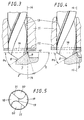
- FIG. 3 shows a detail from FIG. 1 with one into a guide channel 4 to FIG. 3, but after prolonged wear of the grinding wheel
- FIG. 5 is a plan view of a drill tip.
- the various parts of the exemplary embodiment are arranged concentrically around the central axis 1.
- An axis 2 is the spindle of a motor (not shown) arranged in the housing 3.
- the axis 2 is axially fixed in ball bearings 4.
- a grinding wheel carrier 5 is fixed between the bearing 4 and the nut 6.
- An annular grinding wheel 7 is glued to the grinding wheel carrier 5. On its flank facing away from the motor, the grinding wheel has an externally conical grinding surface 8 which, together with an inner cone 9, forms an acute-angled ridge 10.
- the grinding surface 8 forms with its plane of rotation the angle ⁇ 1 of 35 °, the inner cone 9 the angle ⁇ of 75 °. This gives the acute angle ⁇ of 70 ° on the ridge 10.
- a drill guide piece 11, 12 is arranged opposite the grinding surface 8. This is rigidly connected to the housing 3 and is composed of a guide channel body 11 and a guide pin plate 12 rigidly connected to it.
- the guide channel body 11 has guide channels 13 of different diameters which are parallel to the central axis 1 and which externally affect an imaginary cylinder jacket 14 which is coaxial with the central axis 1.
- the diameter of the cylinder jacket 14 is equal to the diameter of the burr 10 of the grinding wheel.
- the guide pin plate 12 has openings 15 aligned with the guide channels 13, into each of which two trapezoidal guide pins 16 project for engagement in the flutes 20 of a drill inserted into the guide channel. These each have two stop edges 17 and are dimensioned such that they permit an approximately 30 ° rotation about its axis of the drill inserted into the guide channel.
- the drill to be ground is inserted by hand into the smallest suitable guide channel 13 and between the guide pins 16 therein until one of its rear grinding surfaces 18 strikes against the rotating grinding surface 8.
- the periphery of the drill touches approximately the ridge 10.
- the drill which is pressed lightly against the grinding surface, is now rotated back and forth a few times between the stop edges 17 of the guide pins. It is then pulled back a little, rotated by 180 °, inserted again to the grinding surface and rotated back and forth. Both relief surfaces are now ground.
- the wear of the grinding wheel is greatest directly on the ridge 10 and decreases continuously with increasing distance from the ridge. In the area of the cutting edge 19 of the drill, the wear of the grinding wheel is minimal. The angle of increase ⁇ of the grinding surface 8 will therefore decrease with increasing wear of the grinding wheel. When the angle of rise ⁇ of the grinding surface has decreased to approximately 30 ° ( ⁇ 2 in FIG. 4), the grinding wheel is replaced. One step in the grinding wheel at the end of the ridge However, the grinding surface cannot be created, since there is no grinding wheel material outside this end of the grinding surface, viewed in the radial direction. The main cutting edges 21 of the drills always remain straight.
Landscapes
- Engineering & Computer Science (AREA)
- Mechanical Engineering (AREA)
- Finish Polishing, Edge Sharpening, And Grinding By Specific Grinding Devices (AREA)
- Polishing Bodies And Polishing Tools (AREA)
- Drilling Tools (AREA)
Claims (1)
- Dispositif pour l'affûtage de forets hélicoïdaux pourvus de surfaces en dépouille (18), et d'une goujure (20) et d'un tranchant principal (21) pour chaque surface en dépouille (18), comportant- un axe médian (1),- une meule (7) disposée en rotation autour de l'axe médian (1) et pourvue d'une surface d'affûtage extérieure conique (8) dont l'extrémité intérieure (10) définit un cercle coaxial, et- un élément de guidage (11, 12) qui est disposé en face de la surface d'affûtage (8) et qui comporte des conduits de guidage (13) globalement parallèles à l'axe médian (1) et, dans ces conduits de guidage (13), des ergots de guidage (16) qui pénètrent dans les goujures (20) d'un foret introduit jusqu'à la surface d'affûtage et qui limitent une rotation autour de son axe, les conduits de guidage (13) étant globalement tangents à une enveloppe cylindrique imaginaire coaxiale (14) qui rencontre l'extrémité intérieure (10) de la surface d'affûtage (8),caractérisé en ce que la surface d'affûtage (8) forme avec une section de surface intérieure conique (9) de la meule (7) qui fait suite à son extrémité intérieure (10) une arête à angle aigu (10).
Applications Claiming Priority (2)
| Application Number | Priority Date | Filing Date | Title |
|---|---|---|---|
| DE4038524 | 1990-12-03 | ||
| DE4038524A DE4038524A1 (de) | 1990-12-03 | 1990-12-03 | Bohrerschleifeinrichtung |
Publications (2)
| Publication Number | Publication Date |
|---|---|
| EP0489410A1 EP0489410A1 (fr) | 1992-06-10 |
| EP0489410B1 true EP0489410B1 (fr) | 1997-09-24 |
Family
ID=6419494
Family Applications (1)
| Application Number | Title | Priority Date | Filing Date |
|---|---|---|---|
| EP91120783A Expired - Lifetime EP0489410B1 (fr) | 1990-12-03 | 1991-12-03 | Dispositif pour l'affûtage de forets |
Country Status (6)
| Country | Link |
|---|---|
| US (1) | US5210977A (fr) |
| EP (1) | EP0489410B1 (fr) |
| JP (1) | JP2556790B2 (fr) |
| AU (1) | AU646905B2 (fr) |
| CA (1) | CA2056162A1 (fr) |
| DE (2) | DE4038524A1 (fr) |
Families Citing this family (10)
| Publication number | Priority date | Publication date | Assignee | Title |
|---|---|---|---|---|
| US5788559A (en) * | 1994-02-25 | 1998-08-04 | Jungnitsch; Paul Lewis | Web adjust drill bit sharpener and method of using |
| US5564871A (en) * | 1994-06-16 | 1996-10-15 | Lagsdin; Andry | Chamfer machine |
| US5676591A (en) * | 1996-08-13 | 1997-10-14 | Huang; Cheng-Hsien | Bit sharpener |
| US9199315B2 (en) | 2000-06-02 | 2015-12-01 | Kennametal Inc. | Twist drill and method for producing a twist drill which method includes forming a flute of a twist drill |
| US6676500B1 (en) * | 2002-11-12 | 2004-01-13 | Sophin Lin | Drill bit sharpener |
| JP2005262341A (ja) * | 2004-03-16 | 2005-09-29 | Noritake Super Abrasive:Kk | Cmpパッドコンディショナー |
| US7488239B2 (en) * | 2006-11-08 | 2009-02-10 | Rolf Tamm | Assembly for grinding electrodes |
| DE102009044855A1 (de) * | 2009-12-10 | 2011-06-16 | Rolf Tamm | Bausatz zum Nachrüsten einer Elektrodenschleifvorrichtung und Elektrodenschleifvorrichtung |
| US8690643B2 (en) * | 2010-07-06 | 2014-04-08 | Western New England University | Portable drill bit sharpener |
| CN102126952A (zh) * | 2010-12-17 | 2011-07-20 | 张家港瀚康化工有限公司 | 丁二酸单乙酯酰氯的制备方法 |
Family Cites Families (11)
| Publication number | Priority date | Publication date | Assignee | Title |
|---|---|---|---|---|
| US2078306A (en) * | 1935-12-26 | 1937-04-27 | Roderick O Baalmann | Drill sharpener |
| US3067548A (en) * | 1960-06-06 | 1962-12-11 | Winslow Product Engineering Co | Drill pointing method and machine |
| SE325210B (fr) * | 1967-05-03 | 1970-06-22 | R Wurscher | |
| US3579924A (en) * | 1967-05-10 | 1971-05-25 | Mataichi Saito | Method for continuously grinding a drill tip end into a normal shape and into a split point |
| US3742652A (en) * | 1970-03-06 | 1973-07-03 | Black & Decker Mfg Co | Drill sharpener |
| DE2343228A1 (de) * | 1973-08-28 | 1975-03-20 | Bosch Gmbh Robert | Bohrerschleifeinrichtung |
| GB2132518B (en) * | 1982-12-17 | 1986-03-26 | Keith Harris | Stand for storing and sharpening chisels, plane irons and drill bits |
| AT380419B (de) * | 1984-02-14 | 1986-05-26 | Wurscher Raimund August | Einrichtung zum schleifen von spiralbohrern |
| AT380418B (de) * | 1984-02-14 | 1986-05-26 | Wurscher Raimund August | Einrichtung zum schleifen von spiralbohrern |
| GB8509028D0 (en) * | 1985-04-09 | 1985-05-15 | Bicc Plc | Honing tool |
| AT385703B (de) * | 1986-07-07 | 1988-05-10 | Wurscher Raimund | Einrichtung zum schleifen von spiralbohrern |
-
1990
- 1990-12-03 DE DE4038524A patent/DE4038524A1/de active Granted
-
1991
- 1991-11-25 CA CA002056162A patent/CA2056162A1/fr not_active Abandoned
- 1991-11-27 US US07/800,618 patent/US5210977A/en not_active Expired - Fee Related
- 1991-11-28 AU AU88273/91A patent/AU646905B2/en not_active Ceased
- 1991-12-02 JP JP3343900A patent/JP2556790B2/ja not_active Expired - Lifetime
- 1991-12-03 DE DE59108860T patent/DE59108860D1/de not_active Expired - Fee Related
- 1991-12-03 EP EP91120783A patent/EP0489410B1/fr not_active Expired - Lifetime
Also Published As
| Publication number | Publication date |
|---|---|
| US5210977A (en) | 1993-05-18 |
| JPH0523956A (ja) | 1993-02-02 |
| AU8827391A (en) | 1992-06-04 |
| DE59108860D1 (de) | 1997-10-30 |
| JP2556790B2 (ja) | 1996-11-20 |
| EP0489410A1 (fr) | 1992-06-10 |
| DE4038524C2 (fr) | 1992-11-12 |
| DE4038524A1 (de) | 1992-06-04 |
| CA2056162A1 (fr) | 1992-06-04 |
| AU646905B2 (en) | 1994-03-10 |
Similar Documents
| Publication | Publication Date | Title |
|---|---|---|
| DE3317441C2 (fr) | ||
| DE3339211C2 (fr) | ||
| DE69002670T2 (de) | Schneideinsatz für einen Fräser. | |
| EP2509745B1 (fr) | Module pour l'équipement ultérieur d'un dispositif de meulage d'électrodes et dispositif de meulage d'électrodes | |
| EP0489410B1 (fr) | Dispositif pour l'affûtage de forets | |
| EP0603121B1 (fr) | Font tubulaire | |
| EP0707129B1 (fr) | Outil de forage avec support et éléments de coupe | |
| DE4032176C2 (de) | Scheibenschneider | |
| EP0195260A2 (fr) | Mandrin et outil de forage pour forage à rotation et rotation-percussion | |
| DE3024852C2 (fr) | ||
| DE2702620A1 (de) | Maschinenreibahle | |
| EP0003816B1 (fr) | Outil de forage pour rocher | |
| EP0468156B1 (fr) | Mandrin de perçage | |
| DE102014207502A1 (de) | Rotationswerkzeug sowie Werkzeugkopf | |
| DE1942955C3 (de) | Einmesserreibahle mit einem mehrere Schneiden aufweisenden Messer korper | |
| DE102020204035B4 (de) | Bohrer | |
| DE3705717A1 (de) | Dosensenker oder hohlbohrkrone sowie herstellungsverfahren hierfuer | |
| EP2509747B1 (fr) | Dispositif de meulage d'électrodes | |
| DD149621A5 (de) | Halter und mitnehmer fuer drehbare schneidwerkzeuge | |
| DE102006052904B4 (de) | Anordnung zum Schleifen von Elektroden | |
| DE19803613C2 (de) | Plandrehkopf | |
| DE102020123783B4 (de) | Vorrichtung zum zerspanenden Bearbeiten | |
| DE19545646A1 (de) | Drehschlag-Wendelbohrer | |
| DE4222704C2 (de) | Vorrichtung zur Aufnahme eines Schneidwerkzeugs zum Nachschleifen desselben | |
| DE202017103022U1 (de) | Schaftfräser |
Legal Events
| Date | Code | Title | Description |
|---|---|---|---|
| PUAI | Public reference made under article 153(3) epc to a published international application that has entered the european phase |
Free format text: ORIGINAL CODE: 0009012 |
|
| AK | Designated contracting states |
Kind code of ref document: A1 Designated state(s): CH DE FR GB IT LI |
|
| 17P | Request for examination filed |
Effective date: 19921209 |
|
| 17Q | First examination report despatched |
Effective date: 19931008 |
|
| GRAG | Despatch of communication of intention to grant |
Free format text: ORIGINAL CODE: EPIDOS AGRA |
|
| GRAH | Despatch of communication of intention to grant a patent |
Free format text: ORIGINAL CODE: EPIDOS IGRA |
|
| GRAH | Despatch of communication of intention to grant a patent |
Free format text: ORIGINAL CODE: EPIDOS IGRA |
|
| GRAA | (expected) grant |
Free format text: ORIGINAL CODE: 0009210 |
|
| AK | Designated contracting states |
Kind code of ref document: B1 Designated state(s): CH DE FR GB IT LI |
|
| PG25 | Lapsed in a contracting state [announced via postgrant information from national office to epo] |
Ref country code: FR Free format text: LAPSE BECAUSE OF FAILURE TO SUBMIT A TRANSLATION OF THE DESCRIPTION OR TO PAY THE FEE WITHIN THE PRESCRIBED TIME-LIMIT Effective date: 19970924 Ref country code: GB Free format text: LAPSE BECAUSE OF FAILURE TO SUBMIT A TRANSLATION OF THE DESCRIPTION OR TO PAY THE FEE WITHIN THE PRESCRIBED TIME-LIMIT Effective date: 19970924 Ref country code: IT Free format text: LAPSE BECAUSE OF FAILURE TO SUBMIT A TRANSLATION OF THE DESCRIPTION OR TO PAY THE FEE WITHIN THE PRE;WARNING: LAPSES OF ITALIAN PATENTS WITH EFFECTIVE DATE BEFORE 2007 MAY HAVE OCCURRED AT ANY TIME BEFORE 2007. THE CORRECT EFFECTIVE DATE MAY BE DIFFERENT FROM THE ONE RECORDED.SCRIBED TIME-LIMIT Effective date: 19970924 |
|
| REG | Reference to a national code |
Ref country code: CH Ref legal event code: EP |
|
| REF | Corresponds to: |
Ref document number: 59108860 Country of ref document: DE Date of ref document: 19971030 |
|
| PG25 | Lapsed in a contracting state [announced via postgrant information from national office to epo] |
Ref country code: LI Free format text: LAPSE BECAUSE OF NON-PAYMENT OF DUE FEES Effective date: 19971231 Ref country code: CH Free format text: LAPSE BECAUSE OF NON-PAYMENT OF DUE FEES Effective date: 19971231 |
|
| EN | Fr: translation not filed | ||
| GBV | Gb: ep patent (uk) treated as always having been void in accordance with gb section 77(7)/1977 [no translation filed] |
Effective date: 19970924 |
|
| PLBE | No opposition filed within time limit |
Free format text: ORIGINAL CODE: 0009261 |
|
| STAA | Information on the status of an ep patent application or granted ep patent |
Free format text: STATUS: NO OPPOSITION FILED WITHIN TIME LIMIT |
|
| REG | Reference to a national code |
Ref country code: CH Ref legal event code: PL |
|
| 26N | No opposition filed | ||
| PGFP | Annual fee paid to national office [announced via postgrant information from national office to epo] |
Ref country code: DE Payment date: 20051221 Year of fee payment: 15 |
|
| PG25 | Lapsed in a contracting state [announced via postgrant information from national office to epo] |
Ref country code: DE Free format text: LAPSE BECAUSE OF NON-PAYMENT OF DUE FEES Effective date: 20070703 |