EP0489475A1 - Appareil à dicter, se tenant dans une main lors du fonctionnement - Google Patents
Appareil à dicter, se tenant dans une main lors du fonctionnement Download PDFInfo
- Publication number
- EP0489475A1 EP0489475A1 EP91203159A EP91203159A EP0489475A1 EP 0489475 A1 EP0489475 A1 EP 0489475A1 EP 91203159 A EP91203159 A EP 91203159A EP 91203159 A EP91203159 A EP 91203159A EP 0489475 A1 EP0489475 A1 EP 0489475A1
- Authority
- EP
- European Patent Office
- Prior art keywords
- side wall
- longitudinal
- head
- housing
- foot
- Prior art date
- Legal status (The legal status is an assumption and is not a legal conclusion. Google has not performed a legal analysis and makes no representation as to the accuracy of the status listed.)
- Granted
Links
- 210000003813 thumb Anatomy 0.000 claims abstract description 31
- 230000007704 transition Effects 0.000 claims description 47
- 210000003811 finger Anatomy 0.000 description 15
- 230000006870 function Effects 0.000 description 10
- 230000006978 adaptation Effects 0.000 description 4
- 210000004932 little finger Anatomy 0.000 description 4
- 238000000034 method Methods 0.000 description 4
- 238000004804 winding Methods 0.000 description 4
- 244000060701 Kaempferia pandurata Species 0.000 description 2
- 235000016390 Uvaria chamae Nutrition 0.000 description 2
- 230000005923 long-lasting effect Effects 0.000 description 2
- 230000015654 memory Effects 0.000 description 2
- 230000000284 resting effect Effects 0.000 description 2
- 230000002349 favourable effect Effects 0.000 description 1
- 239000004065 semiconductor Substances 0.000 description 1
Images
Classifications
-
- G—PHYSICS
- G11—INFORMATION STORAGE
- G11B—INFORMATION STORAGE BASED ON RELATIVE MOVEMENT BETWEEN RECORD CARRIER AND TRANSDUCER
- G11B25/00—Apparatus characterised by the shape of record carrier employed but not specific to the method of recording or reproducing, e.g. dictating apparatus; Combinations of such apparatus
- G11B25/06—Apparatus characterised by the shape of record carrier employed but not specific to the method of recording or reproducing, e.g. dictating apparatus; Combinations of such apparatus using web-form record carriers, e.g. tape
- G11B25/063—Apparatus characterised by the shape of record carrier employed but not specific to the method of recording or reproducing, e.g. dictating apparatus; Combinations of such apparatus using web-form record carriers, e.g. tape using tape inside container
-
- G—PHYSICS
- G11—INFORMATION STORAGE
- G11B—INFORMATION STORAGE BASED ON RELATIVE MOVEMENT BETWEEN RECORD CARRIER AND TRANSDUCER
- G11B33/00—Constructional parts, details or accessories not provided for in the other groups of this subclass
- G11B33/12—Disposition of constructional parts in the apparatus, e.g. of power supply, of modules
- G11B33/121—Disposition of constructional parts in the apparatus, e.g. of power supply, of modules the apparatus comprising a single recording/reproducing device
Definitions
- the invention relates to a dictation machine, which is held in one hand during operation, with a substantially elongated housing which extends in the longitudinal direction between a head-side area and a foot-side area and which has a top wall, a bottom wall, a first longitudinal side wall and a second Longitudinal side wall and a head-side transverse side wall and a foot-side transverse side wall, and with a provided on the first longitudinal side wall in the head-side area, operable with the thumb of a hand for switching on and off at least one operating function of the dictation machine.
- Such a dictation machine is known, for example, from US Pat. No. 3,877,074. Such a dictation machine is also known from Austrian Patent No. 348 789.
- Each of these two known dictation machines which are also very often referred to as pocket dictation machines, has an elongated, exactly cuboid-shaped housing, which has a sliding button that can be actuated with the thumb of a hand as a handle for switching on operating modes on a first perfectly straight longitudinal side wall in its head area of the dictation machine.
- the thumb must be held in an uncomfortable position relatively far from the palm of the hand in order to hold the device and to be able to actuate the handle on the first longitudinal side wall with the thumb , which forces the user of the device to hold the device open further than is favorable for a secure hold of the device, and what to the user of the device if the device takes longer Use is perceived as uncomfortable due to the unnatural posture of the thumb and leads to a relatively rapid fatigue of the hand with which the device is held during operation.
- the invention has set itself the task of avoiding the difficulties mentioned above and designing a dictation machine in accordance with the above-mentioned paragraph in such a way that the same is held comfortably and securely by hand during operation, in which the thumb must interact with the handle which can be actuated by it and that the thumb can be held in a natural and comfortable position even when the handle is operated, so that practically no signs of fatigue occur in the hand holding the device, even during a long dictation process.
- the invention is characterized in that the first longitudinal side wall of the housing is angled in the head-side region in the direction of the second longitudinal side wall and has two wall sections connected to one another via a back-like transition region and in that the longitudinal direction of the extending between the back-like transition region and the head-side transverse side wall angled head-side wall section of the first longitudinal side wall and the longitudinal direction of the housing enclose an angle in an angular range of 3 o to 50 o with one another and that the handle which can be actuated with the thumb is provided on the angled head-side wall section of the first longitudinal side wall.
- a particularly advantageous ergonomic design of a dictation device which is held in one hand during operation, is obtained, in which advantageously there are practically no signs of fatigue in the hand holding the device even during a long-lasting dictation process, because of the angled design the first long side wall and the provision of the handle which can be actuated by the thumb on the angled head-side wall section of the first long side wall of the thumb assumes a natural and relaxed position when the handle is operated. It is also achieved that when actuated the handle with the thumb does not need to be opened unnecessarily wide, so that the device at least partially encompasses the device, so that even when the handle is actuated with the thumb, the device is always securely held by hand.
- a pocket dictation machine which has a housing which is angled in the side view of the head, the two longitudinal side walls of which, also those on which a handle which can be actuated with the thumb of a hand holding the dictation machine is provided, but run perfectly straight.
- a remote control is known from German Utility Model No. 86 28 999, which also has a housing which is angled in a side view on the head side, but whose two longitudinal side walls also run completely straight, and in which no handle is provided on the longitudinal side walls, but only on the ceiling wall thereof . From the German utility model No.
- a so-called table terminal is known as a terminal for hands-free systems with a housing with slightly angled long side walls, but it is not a dictation machine that is held in one hand during operation, and none on the long side walls Handle is provided, but only on the ceiling wall of this device.
- the degree of angulation of the first longitudinal side wall of the device housing in the area on the head side there are a number of possibilities with regard to the degree of angulation of the first longitudinal side wall of the device housing in the area on the head side. It has proven to be particularly advantageous if the longitudinal direction of the angled head-side wall section of the first longitudinal side wall, which extends between the back-like transition region and the head-side transverse side wall, and the longitudinal direction of the housing enclose an angle of 20 ° with one another. This has been proven to be particularly advantageous in terms of a particularly pleasant and convenient actuation of the handle which can be actuated with the thumb.
- the second longitudinal side wall of the housing in the head-side region is angled in the same direction as the first longitudinal side wall and has two wall sections connected to one another via a fillet-like transition region. This ensures that the dictation machine is held securely by hand, because the finger resting in the throat-like transition area practically precludes the dictation machine from moving in the hand; This also applies when the handle provided on the first longitudinal side wall is actuated with the thumb.
- the back-like transition region of the first longitudinal side wall and the throat-like transition region of the second longitudinal side wall lie essentially on a connecting line which runs perpendicular to the longitudinal direction of the housing. This has also proven to be advantageous in terms of minimizing the fatigue of the hand holding the device and operating the thumb-operated handle as conveniently as possible. Furthermore, this is advantageous with regard to a design which is ergonomically adapted as well as possible to the shape of a closed hand.
- the angled head-side wall section of the first longitudinal side wall, which extends between the back-like transition area and the head-side transverse side wall, and the angled head-side wall section of the second longitudinal side wall, which extends between the groove-like transition area and the head-side transverse side wall run essentially parallel to one another. This is also advantageous in terms of an ergonomically optimal training adapted to the shape of a closed hand and good hold of the dictation machine.
- the distance between the two angled head-side wall sections is opposite the first and second longitudinal side walls the distance between the two foot-side wall sections of the first and second longitudinal side walls is reduced, starting from the throat-like transition region of the second longitudinal side wall.
- a relatively pronounced throat-like transition area is obtained, as a result of which a housing design that is particularly well adapted to the hand shape is achieved, which takes into account the different distances between the fingers and the thumb, and as a result of which the dictation machine is held particularly securely.
- the longitudinal direction of the foot-side wall section of the second longitudinal side wall which extends between the throat-like transition region and the foot-side transverse side wall, runs essentially parallel to the longitudinal direction of the housing.
- This is advantageous with regard to a housing design which is adapted as ergonomically as possible to the shape of the palm of the hand in the area of the transitions of the little finger, the ring finger and the middle finger into the palm of the hand.
- a further handle for switching on and off at least one further operating function of the dictation device is provided in the throat-like transition region of the second longitudinal side wall.
- the further handle is designed as a push button.
- the additional handle is particularly easy and pleasant to operate.
- first longitudinal side wall of the housing is also angled in the foot-side region in the direction of the second longitudinal side wall and the extending angled foot-side wall portion of the first longitudinal side wall and the longitudinal direction of the housing at an angle in an angular range of 2 o o include the longitudinal direction between the ridge-like transitional portion and the lower transverse side wall and 20 to each other. This is very advantageous in terms of a good adaptation of the design of the housing to the shape of the hand in the area of the ball of the hand.
- Hiebei has proven to be particularly advantageous if the longitudinal direction of the angled foot-side wall section of the first longitudinal side wall extending between the back-like transition region and the foot-side transverse side wall and the longitudinal direction of the housing enclose an angle of 6 ° with one another. In this context, this has proven to be the cheapest training.
- the housing is tapered in the region of its end lying at the foot-side transverse side wall in the region of its bottom wall towards the foot-side transverse side wall.
- a particularly good adaptation of the housing with its base region to the shape of a hand is achieved in this way in the region of the palm of the hand lying between the finger root of the little finger and the end of the palm of the hand facing away from the thumb.
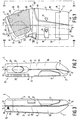
- FIG. 1 shows approximately in natural size in plan view a dictation machine according to a first embodiment, which is held in operation in one hand and the housing of which has two angled or kinked longitudinal side walls.
- FIG. 2 shows the dictation machine according to FIG. 1 in a side view according to line II-II in FIG. 1.
- FIG. 3 shows the dictation machine according to FIG. 1 in a side view according to line III-III in FIG. 1.
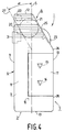
- FIG. 4 shows approximately in FIG Natural size in plan view of a dictation machine according to a second embodiment, the is held in one hand during operation and its housing has an angled longitudinal side wall.
- FIGS. 1 to 3 show a dictation device 1 according to a first embodiment, which is held in one hand during operation and which is very often referred to as a so-called pocket dictation device.
- the dictation machine 1 has an essentially elongated housing 2, which consists of a bottom-side housing trough 3 and a top-side housing trough 4.
- the housing extends in its longitudinal direction 5, which is indicated by a dash-dotted line in FIGS. 1 to 3, between a head-side region 6 and a foot-side region 7.
- the longitudinal direction 5 of the housing 2 is essentially due to the central longitudinal extent of the foot-side region 7 of the housing 2 set.
- the housing 2 has a top wall 8, a bath wall 9, a first longitudinal side wall 10 and a second longitudinal side wall 11 and a head-side transverse side wall 12 and a foot-side transverse side wall 13.
- the dictation machine 1 has a receiving space into which two rotating drivable winding mandrels 14 and 15 protrude, which serve to drive two winding cores lying next to one another in a magnetic tape cassette.
- the dictation device 1 has a cover 17 which can be pivoted about a pivot axis 16 indicated schematically in FIG.
- a transparent window 18 is provided, through which the winding mandrel 14 is visible.
- a snap-in closure cover 19 is provided, with which a receiving space for batteries for the energy supply of the dictation machine 1 is closed.
- the ceiling wall 8 is a schematic in the head area 6 of the housing 2 indicated, provided with openings wall portion 20, behind which a speaker 21 schematically indicated in Figure 1 and a schematically indicated microphone 22 are arranged.
- the dictation machine 1 is provided with a handle 23, which is provided on the first longitudinal side wall 10 in the head-side region 6 and can be actuated with the thumb of a hand, for switching on and off at least one operating function of the dictation machine 1.
- the handle is designed as a slide button which is guided so as to be displaceable in the longitudinal direction of the first longitudinal side wall 10 and which, for example, is adjustable between four different operating positions, an operating function of the dictation device being able to be activated with it in each operating position.
- These four operating functions are the operating functions "Fast forward”, “Normal forward”, "Stop” and “Fast rewind” in succession.
- the first longitudinal side wall 10 of the housing 2 is angled in the head-side region 6 in the direction of the second longitudinal side wall 11.
- the first longitudinal side wall 10 has two wall sections 25 and 26 which are connected to one another via a back-like transition region 24 which in the present case runs in a circular arc.
- the longitudinal direction 27 of the angled head-side wall section 25 of the first longitudinal side wall 10 which extends between the back-like transition region 24 and the head-side transverse side wall 12, and which is indicated in FIG. 1 with a dash-dotted line, and the longitudinal direction 5 of the Housing 2 an angle ⁇ with each other, which in the present case has a value of 20 o .
- This angled course of the first longitudinal side wall 10 and the provision of the handle 23 on the angled head-side wall section 25 of the first longitudinal side wall 10 results in an ergonomically particularly advantageous embodiment of such a dictation device 1, in which advantageously Even with a long-lasting dictation process, practically no signs of fatigue occur in the hand holding the dictation machine 1, because the thumb can always assume a natural and relaxed position when the handle 23 is actuated.
- the second longitudinal side wall 11 of the housing 2 is additionally angled in the head-side region 6 in the same direction as the first longitudinal side wall 10.
- the second longitudinal side wall 11 has two wall sections 29 and 30 which are connected to one another via a fillet-like transition region 28. This ensures that the dictation device 1 is held securely because the fingers resting in the throat-like transition region 28 practically preclude the dictation device 1 from moving in the hand.
- the back-like transition area 24 of the first longitudinal side wall 10 and the throat-like transition area 28 of the second longitudinal side wall 11 lie essentially on a connecting line 36, which is also shown in FIG. 1 with a dash-dotted line and which runs perpendicular to the longitudinal direction 5 of the housing 2.
- This measure achieves an ergonomic design of the dictation machine 1 which is as well adapted to the shape of a closed hand as possible. Furthermore, this measure has also proven to be advantageous with regard to the lowest possible fatigue of the hand holding the dictation machine 1 and to the most convenient operation of the handle 23 which can be actuated with the thumb.
- the distance, namely the distance perpendicular to the longitudinal direction 27, between the two angled head-side wall sections 25 and 29 of the first and second longitudinal side walls 10 and 11 is relative to the distance, namely the distance perpendicular to the longitudinal direction 5 of the Housing 2, between the two foot-side wall sections 26 and 30 of the first and second longitudinal side walls 10 and 11, starting from the throat-like transition region 28 of the second longitudinal side wall 11, is reduced.
- a relatively strongly pronounced throat-like transition region 28 is obtained, which is advantageous with regard to a housing design that is particularly well adapted to the shape of the hand, since such a housing design takes into account the different distances between the fingers and the thumb.
- the strong pronounced throat-like transition area 28 also ensures that the dictation machine 1 is held securely.
- the longitudinal direction of the foot-side wall section 30 of the second longitudinal side wall 11, which extends between the throat-like transition region 28 and the foot-side transverse side wall 13, runs parallel to the longitudinal direction 5 of the housing 2.
- Such a course of the foot-side wall section 30 of the second longitudinal side wall 11 is advantageous because in this way a housing design is achieved which is ergonomically matched as well as possible to the course of the palm of the hand in the area of the transitions of the little finger, the ring finger and the middle finger into the palm of the hand.
- a further handle 31 for switching on and off a further operating function of the dictation device 1, namely the operating function “recording”, is provided in the dictation device 1.
- the further handle 31 is advantageous formed as a push button, which is pivotally mounted about a pivot axis 32 in the interior of the device and is held in the rest position shown in FIG. 1 by means of a return spring, not shown, acting on it: the provision of the further handle 31 in the throat-like transition region 28 makes it particularly special ensured in a simple manner that the finger cooperating with this additional handle 31 always remains securely in operative connection with the same, without the risk of the finger in question sliding off this additional handle 31. Characterized in that the further handle 31 is designed as a push button, a particularly simple and pleasant operation of this additional handle is achieved.
- Part of a knurled wheel 34 protrudes from the interior of the device through a breakthrough 33 provided in the transverse side wall 12 on the head side, which is not shown in FIG. 3, by means of which a potentiometer for setting the playback volume can be set.
- the turning of the knurled wheel 34 can be done in a simple manner with the index finger of the hand holding the dictation machine 1, wherein when the knurled wheel 34 is turned with the index finger, advantageously no reaching around or moving the other fingers is necessary.
- the first longitudinal side wall 10 of the housing 2 is also angled in the foot region 7 in the direction of the second longitudinal side wall 11.
- the longitudinal direction 35 of the angled foot-side wall section 26 of the first longitudinal side wall 10, which extends between the back-like transition region 24 and the foot-side transverse side wall 13, which is indicated by a dash-dotted line in FIG. 1, and the longitudinal direction 5 of the housing 2 form an angle ⁇ , which in the present case has a value of 6 o .
- the housing 2 is in the region of its end lying at the foot-side transverse side wall 13 in the region of its bottom wall 9 foot-side transverse side wall 13 tapered. This achieves a particularly good adaptation of the housing 2 of the dictation machine 1 with its base region to the shape of a hand in the region of the palm of the hand lying between the finger root of the little finger and the end of the palm of the hand facing away from the thumb.
- FIG. 4 shows a dictation machine 1 according to a second exemplary embodiment of the invention.
- a cassette with a magnetic tape can also be used as a storage medium in this dictation machine 1.
- the cassette with its longitudinal direction parallel to the longitudinal direction 5 of the dictation machine 1 can be inserted into a recording space of the same.
- This receiving space, into which two rotationally drivable angle mandrels 14 and 15 project for driving two winding cores accommodated in a cassette can be closed with a cover 17 which can be pivoted about a pivot axis 16 which is schematically indicated by a dash-dotted line.
- the dictation machine 1 has an elongated housing 2 which extends in its longitudinal direction 5 between a region 6 on the head side and a region 7 on the foot side.
- the housing 2 consists of a top wall 8, a bottom wall 9, a first longitudinal side wall 10 and a second longitudinal side wall 11 and a head-side transverse side wall 12 and a foot-side transverse side wall 13.
- the top wall 8 has a schematically indicated area 20 with openings in the head-side area 6 on, behind which a schematically indicated loudspeaker 21 and a schematically indicated microphone 22 lie.
- a handle 31 designed as a push button is provided for switching on the recording function of the dictation machine 1.
- a handle 23 which is also designed as a slide button in this case and can be used to switch on the same operating functions in the present dictation machine 1 as with the corresponding handle in the dictation machine according to FIGS. 1 to 3.
- the first longitudinal side wall 10 of the housing 2 is in the region 6 on the head side angled towards the second longitudinal side wall 11.
- the first longitudinal side wall 10 has two wall sections 25 and 26 which are connected to one another via a back-like transition region 24 which is only very small in the present case.
- the longitudinal direction include 27 of the 12 extending angled head-side wall portion between the ridge-like transitional portion 24 and the head-side transverse side wall 25 of the first longitudinal side wall 10 and the longitudinal direction 5 of the housing 2 an angle ⁇ with each other, a having a value of 30 o in this device.
- the handle 23 which can be actuated with the thumb of one hand and is designed as a sliding button.
- an ergonomically advantageous design of the dictation machine 1, which is held in one hand during operation is obtained.
- the thumb operating the handle 23 can be held in a comfortable and natural position even while the handle 23 is being operated. Since the thumb assumes a natural and relaxed position even when the handle 23 is actuated, the hand never needs to be opened unnecessarily, so that the dictation machine 1 is always securely held during operation.
- the handle provided on the angled head-side wall section is each designed as a sliding button which can be displaced in the longitudinal direction of this wall section.
- This handle can also be designed as a slide button that can be moved transversely to the longitudinal direction of this wall section, or as a push button, as a rocker button or as a rotatable switching wheel.
- dictation machines are devices in which magnetic tape cassettes can be inserted, which thus use a magnetic tape as a storage medium.
- the measures according to the invention can, however, also be used with other dictation devices which are held in one hand during operation, namely for example with dictation devices in which optically scannable recording media can be used as storage media, or with dictation devices which use read-only memories, for example semiconductor memories, as storage media .
Landscapes
- Casings For Electric Apparatus (AREA)
- Printers Characterized By Their Purpose (AREA)
- Bag Frames (AREA)
- Coating Apparatus (AREA)
- Adhesives Or Adhesive Processes (AREA)
- Seal Device For Vehicle (AREA)
- Control And Other Processes For Unpacking Of Materials (AREA)
- Manipulator (AREA)
- Footwear And Its Accessory, Manufacturing Method And Apparatuses (AREA)
- Bending Of Plates, Rods, And Pipes (AREA)
- Cartons (AREA)
Applications Claiming Priority (2)
| Application Number | Priority Date | Filing Date | Title |
|---|---|---|---|
| AT2473/90 | 1990-12-06 | ||
| AT0247390A AT395491B (de) | 1990-12-06 | 1990-12-06 | Diktiergeraet, das beim betrieb in einer hand gehalten wird |
Publications (2)
| Publication Number | Publication Date |
|---|---|
| EP0489475A1 true EP0489475A1 (fr) | 1992-06-10 |
| EP0489475B1 EP0489475B1 (fr) | 1996-03-27 |
Family
ID=3534986
Family Applications (1)
| Application Number | Title | Priority Date | Filing Date |
|---|---|---|---|
| EP91203159A Expired - Lifetime EP0489475B1 (fr) | 1990-12-06 | 1991-12-03 | Appareil à dicter, se tenant dans une main lors du fonctionnement |
Country Status (6)
| Country | Link |
|---|---|
| US (1) | US5235571A (fr) |
| EP (1) | EP0489475B1 (fr) |
| JP (1) | JP3014195B2 (fr) |
| AT (2) | AT395491B (fr) |
| DE (1) | DE59107617D1 (fr) |
| ES (1) | ES2087236T3 (fr) |
Families Citing this family (8)
| Publication number | Priority date | Publication date | Assignee | Title |
|---|---|---|---|---|
| WO1995028711A1 (fr) * | 1994-04-19 | 1995-10-26 | Comp General Corporation | Ensemble commutateur multi-directionnel pour dispositifs d'enregistrement portatifs |
| US5898916A (en) * | 1994-06-30 | 1999-04-27 | Dictaphone Corporation | Cordless telephone for use with dictation system |
| US5477511A (en) * | 1994-07-13 | 1995-12-19 | Englehardt; C. Duane | Portable documentation system |
| US5956298A (en) * | 1997-11-10 | 1999-09-21 | Gough; Jesse Lynn | Voice prompting and indexing dictation recorder |
| US6282154B1 (en) | 1998-11-02 | 2001-08-28 | Howarlene S. Webb | Portable hands-free digital voice recording and transcription device |
| US6163508A (en) * | 1999-05-13 | 2000-12-19 | Ericsson Inc. | Recording method having temporary buffering |
| KR100354300B1 (ko) * | 2000-03-08 | 2002-09-28 | 주식회사 심스밸리 | 보이스 레코더 |
| JP2022071331A (ja) * | 2020-10-28 | 2022-05-16 | ミネベアミツミ株式会社 | ベース部材およびその製造方法、スピンドルモータ並びにハードディスク駆動装置 |
Citations (3)
| Publication number | Priority date | Publication date | Assignee | Title |
|---|---|---|---|---|
| US3877074A (en) * | 1972-04-14 | 1975-04-08 | Compur Werk Gmbh & Co | Miniature tape recording and reproducing apparatus with one finger controlled switching arrangement |
| US4602358A (en) * | 1979-09-18 | 1986-07-22 | Olympus Optical Co., Ltd. | Car stereo set |
| GB2228820A (en) * | 1988-03-31 | 1990-09-05 | Seiko Epson Corp | Portable record reproducer |
Family Cites Families (5)
| Publication number | Priority date | Publication date | Assignee | Title |
|---|---|---|---|---|
| AT348789B (de) * | 1977-02-18 | 1979-03-12 | Philips Nv | Geraet der nachrichtentechnik |
| DE3049319A1 (de) * | 1980-12-29 | 1982-07-29 | Balda-Werke Photographische Geräte und Kunststoff GmbH & Co KG, 4980 Bünde | Taschendiktiergeraet |
| DE8310908U1 (de) * | 1983-04-13 | 1984-02-02 | HGA-Gehrke Sprechtechnik GmbH + Co KG, 8501 Allersberg | Tischterminal als endgeraet mit freisprechmoeglichkeit |
| US4870516A (en) * | 1983-05-20 | 1989-09-26 | Dictaphone Corporation | Portable dictating machine |
| DE8628999U1 (de) * | 1986-10-30 | 1986-12-11 | Deutsche Thomson-Brandt Gmbh, 7730 Villingen-Schwenningen | IR-Fernsteuerungs-Geber |
-
1990
- 1990-12-06 AT AT0247390A patent/AT395491B/de not_active IP Right Cessation
-
1991
- 1991-12-03 ES ES91203159T patent/ES2087236T3/es not_active Expired - Lifetime
- 1991-12-03 EP EP91203159A patent/EP0489475B1/fr not_active Expired - Lifetime
- 1991-12-03 AT AT91203159T patent/ATE136150T1/de not_active IP Right Cessation
- 1991-12-03 DE DE59107617T patent/DE59107617D1/de not_active Expired - Fee Related
- 1991-12-04 US US07/804,263 patent/US5235571A/en not_active Expired - Fee Related
- 1991-12-05 JP JP3322040A patent/JP3014195B2/ja not_active Expired - Lifetime
Patent Citations (3)
| Publication number | Priority date | Publication date | Assignee | Title |
|---|---|---|---|---|
| US3877074A (en) * | 1972-04-14 | 1975-04-08 | Compur Werk Gmbh & Co | Miniature tape recording and reproducing apparatus with one finger controlled switching arrangement |
| US4602358A (en) * | 1979-09-18 | 1986-07-22 | Olympus Optical Co., Ltd. | Car stereo set |
| GB2228820A (en) * | 1988-03-31 | 1990-09-05 | Seiko Epson Corp | Portable record reproducer |
Also Published As
| Publication number | Publication date |
|---|---|
| AT395491B (de) | 1993-01-25 |
| EP0489475B1 (fr) | 1996-03-27 |
| DE59107617D1 (de) | 1996-05-02 |
| ATA247390A (de) | 1992-05-15 |
| ES2087236T3 (es) | 1996-07-16 |
| JPH04268278A (ja) | 1992-09-24 |
| JP3014195B2 (ja) | 2000-02-28 |
| ATE136150T1 (de) | 1996-04-15 |
| US5235571A (en) | 1993-08-10 |
Similar Documents
| Publication | Publication Date | Title |
|---|---|---|
| EP0034756B1 (fr) | Réceptacle pour matériau en forme de bande | |
| DE3245460C2 (fr) | ||
| EP0489475B1 (fr) | Appareil à dicter, se tenant dans une main lors du fonctionnement | |
| DE2734953A1 (de) | Inhalator, insbesondere tascheninhalator | |
| DE9105910U1 (de) | Haarbürste | |
| DE2261892A1 (de) | Gebrauchsbehaelter fuer kosmetische stifte, beispielsweise lippenstiftbehaelter | |
| DE3111871A1 (de) | Elektrischer rasierapparat | |
| DE1547034B2 (de) | Tonbandkassettengeraet | |
| DE602004013083T2 (de) | Behälter, der in der Öffnungsstellung einen Ständer bildet | |
| DE68915683T2 (de) | Elektronisches Gerät mit kleinen Abmessungen. | |
| DE3733935A1 (de) | Speicherbehaelter fuer ersatzminen | |
| DE3000411C2 (de) | Kosmetikgerät | |
| DE3723049A1 (de) | Buerste, insbesondere zum kaemmen des kopfhaares | |
| USD263350S (en) | Combined sheath and thread snips | |
| DE2122795A1 (de) | Betriebsart-Umstellvorrichtung für ein Miniatur-Kassettentonbandgerät | |
| DE69401786T2 (de) | Stütze eines Filterbeutels in einem Staubsauger | |
| DE3146903A1 (de) | "halter fuer schutzschilde" | |
| DE19531066C1 (de) | Computer-Maus | |
| EP0836810A1 (fr) | Distributeur de cigarettes | |
| DE3122060C2 (de) | Schnurlose Handstückanordnung für zahnärztliche Behandlungszwecke | |
| DE3830934A1 (de) | Schere, insbesondere haarschneideschere fuer friseure | |
| DE2535891A1 (de) | Verstellbare halterung fuer den handgriff einer dusche | |
| DE19812602A1 (de) | Halter und Dose für Dentaleinheiten | |
| DE2601512C2 (de) | Kanülenbehälter | |
| CH590637A5 (en) | Lipstick casing for single handed use - has housing with two symmetrical halves and plastic strips attached to holder |
Legal Events
| Date | Code | Title | Description |
|---|---|---|---|
| PUAI | Public reference made under article 153(3) epc to a published international application that has entered the european phase |
Free format text: ORIGINAL CODE: 0009012 |
|
| AK | Designated contracting states |
Kind code of ref document: A1 Designated state(s): AT CH DE ES FR GB IT LI |
|
| 17P | Request for examination filed |
Effective date: 19921208 |
|
| 17Q | First examination report despatched |
Effective date: 19950302 |
|
| GRAA | (expected) grant |
Free format text: ORIGINAL CODE: 0009210 |
|
| AK | Designated contracting states |
Kind code of ref document: B1 Designated state(s): AT CH DE ES FR GB IT LI |
|
| REF | Corresponds to: |
Ref document number: 136150 Country of ref document: AT Date of ref document: 19960415 Kind code of ref document: T |
|
| REF | Corresponds to: |
Ref document number: 59107617 Country of ref document: DE Date of ref document: 19960502 |
|
| ITF | It: translation for a ep patent filed | ||
| REG | Reference to a national code |
Ref country code: ES Ref legal event code: BA2A Ref document number: 2087236 Country of ref document: ES Kind code of ref document: T3 |
|
| ET | Fr: translation filed | ||
| GBT | Gb: translation of ep patent filed (gb section 77(6)(a)/1977) |
Effective date: 19960611 |
|
| REG | Reference to a national code |
Ref country code: ES Ref legal event code: FG2A Ref document number: 2087236 Country of ref document: ES Kind code of ref document: T3 |
|
| PLBE | No opposition filed within time limit |
Free format text: ORIGINAL CODE: 0009261 |
|
| STAA | Information on the status of an ep patent application or granted ep patent |
Free format text: STATUS: NO OPPOSITION FILED WITHIN TIME LIMIT |
|
| 26N | No opposition filed | ||
| PGFP | Annual fee paid to national office [announced via postgrant information from national office to epo] |
Ref country code: AT Payment date: 19971219 Year of fee payment: 7 |
|
| PGFP | Annual fee paid to national office [announced via postgrant information from national office to epo] |
Ref country code: FR Payment date: 19971223 Year of fee payment: 7 Ref country code: ES Payment date: 19971223 Year of fee payment: 7 |
|
| PGFP | Annual fee paid to national office [announced via postgrant information from national office to epo] |
Ref country code: CH Payment date: 19980317 Year of fee payment: 7 |
|
| REG | Reference to a national code |
Ref country code: CH Ref legal event code: PFA Free format text: PHILIPS ELECTRONICS N.V. TRANSFER- KONINKLIJKE PHILIPS ELECTRONICS N.V. |
|
| REG | Reference to a national code |
Ref country code: FR Ref legal event code: CD |
|
| PG25 | Lapsed in a contracting state [announced via postgrant information from national office to epo] |
Ref country code: AT Free format text: LAPSE BECAUSE OF NON-PAYMENT OF DUE FEES Effective date: 19981203 |
|
| PG25 | Lapsed in a contracting state [announced via postgrant information from national office to epo] |
Ref country code: LI Free format text: LAPSE BECAUSE OF THE APPLICANT RENOUNCES Effective date: 19981231 Ref country code: CH Free format text: LAPSE BECAUSE OF THE APPLICANT RENOUNCES Effective date: 19981231 |
|
| REG | Reference to a national code |
Ref country code: ES Ref legal event code: PC2A |
|
| REG | Reference to a national code |
Ref country code: CH Ref legal event code: PL |
|
| PG25 | Lapsed in a contracting state [announced via postgrant information from national office to epo] |
Ref country code: FR Free format text: LAPSE BECAUSE OF NON-PAYMENT OF DUE FEES Effective date: 19990831 |
|
| REG | Reference to a national code |
Ref country code: FR Ref legal event code: ST |
|
| PG25 | Lapsed in a contracting state [announced via postgrant information from national office to epo] |
Ref country code: ES Free format text: LAPSE BECAUSE OF NON-PAYMENT OF DUE FEES Effective date: 19991204 |
|
| PGFP | Annual fee paid to national office [announced via postgrant information from national office to epo] |
Ref country code: GB Payment date: 19991221 Year of fee payment: 9 |
|
| PGFP | Annual fee paid to national office [announced via postgrant information from national office to epo] |
Ref country code: DE Payment date: 20000223 Year of fee payment: 9 |
|
| PG25 | Lapsed in a contracting state [announced via postgrant information from national office to epo] |
Ref country code: GB Free format text: LAPSE BECAUSE OF NON-PAYMENT OF DUE FEES Effective date: 20001203 |
|
| GBPC | Gb: european patent ceased through non-payment of renewal fee |
Effective date: 20001203 |
|
| PG25 | Lapsed in a contracting state [announced via postgrant information from national office to epo] |
Ref country code: DE Free format text: LAPSE BECAUSE OF NON-PAYMENT OF DUE FEES Effective date: 20011002 |
|
| REG | Reference to a national code |
Ref country code: ES Ref legal event code: FD2A Effective date: 20000114 |
|
| PG25 | Lapsed in a contracting state [announced via postgrant information from national office to epo] |
Ref country code: IT Free format text: LAPSE BECAUSE OF NON-PAYMENT OF DUE FEES;WARNING: LAPSES OF ITALIAN PATENTS WITH EFFECTIVE DATE BEFORE 2007 MAY HAVE OCCURRED AT ANY TIME BEFORE 2007. THE CORRECT EFFECTIVE DATE MAY BE DIFFERENT FROM THE ONE RECORDED. Effective date: 20051203 |