EP0489549A2 - Elektrischer Drahtverbinder - Google Patents
Elektrischer Drahtverbinder Download PDFInfo
- Publication number
- EP0489549A2 EP0489549A2 EP91311083A EP91311083A EP0489549A2 EP 0489549 A2 EP0489549 A2 EP 0489549A2 EP 91311083 A EP91311083 A EP 91311083A EP 91311083 A EP91311083 A EP 91311083A EP 0489549 A2 EP0489549 A2 EP 0489549A2
- Authority
- EP
- European Patent Office
- Prior art keywords
- wire
- housing
- terminal
- arms
- arm
- Prior art date
- Legal status (The legal status is an assumption and is not a legal conclusion. Google has not performed a legal analysis and makes no representation as to the accuracy of the status listed.)
- Granted
Links
Images





Classifications
-
- H—ELECTRICITY
- H01—ELECTRIC ELEMENTS
- H01R—ELECTRICALLY-CONDUCTIVE CONNECTIONS; STRUCTURAL ASSOCIATIONS OF A PLURALITY OF MUTUALLY-INSULATED ELECTRICAL CONNECTING ELEMENTS; COUPLING DEVICES; CURRENT COLLECTORS
- H01R11/00—Individual connecting elements providing two or more spaced connecting locations for conductive members which are, or may be, thereby interconnected, e.g. end pieces for wires or cables supported by the wire or cable and having means for facilitating electrical connection to some other wire, terminal, or conductive member, blocks of binding posts
- H01R11/11—End pieces or tapping pieces for wires, supported by the wire and for facilitating electrical connection to some other wire, terminal or conductive member
- H01R11/20—End pieces terminating in a needle point or analogous contact for penetrating insulation or cable strands
-
- H—ELECTRICITY
- H01—ELECTRIC ELEMENTS
- H01R—ELECTRICALLY-CONDUCTIVE CONNECTIONS; STRUCTURAL ASSOCIATIONS OF A PLURALITY OF MUTUALLY-INSULATED ELECTRICAL CONNECTING ELEMENTS; COUPLING DEVICES; CURRENT COLLECTORS
- H01R4/00—Electrically-conductive connections between two or more conductive members in direct contact, i.e. touching one another; Means for effecting or maintaining such contact; Electrically-conductive connections having two or more spaced connecting locations for conductors and using contact members penetrating insulation
- H01R4/24—Connections using contact members penetrating or cutting insulation or cable strands
- H01R4/2416—Connections using contact members penetrating or cutting insulation or cable strands the contact members having insulation-cutting edges, e.g. of tuning fork type
- H01R4/242—Connections using contact members penetrating or cutting insulation or cable strands the contact members having insulation-cutting edges, e.g. of tuning fork type the contact members being plates having a single slot
- H01R4/2425—Flat plates, e.g. multi-layered flat plates
- H01R4/2429—Flat plates, e.g. multi-layered flat plates mounted in an insulating base
- H01R4/2433—Flat plates, e.g. multi-layered flat plates mounted in an insulating base one part of the base being movable to push the cable into the slot
-
- H—ELECTRICITY
- H01—ELECTRIC ELEMENTS
- H01R—ELECTRICALLY-CONDUCTIVE CONNECTIONS; STRUCTURAL ASSOCIATIONS OF A PLURALITY OF MUTUALLY-INSULATED ELECTRICAL CONNECTING ELEMENTS; COUPLING DEVICES; CURRENT COLLECTORS
- H01R12/00—Structural associations of a plurality of mutually-insulated electrical connecting elements, specially adapted for printed circuits, e.g. printed circuit boards [PCB], flat or ribbon cables, or like generally planar structures, e.g. terminal strips, terminal blocks; Coupling devices specially adapted for printed circuits, flat or ribbon cables, or like generally planar structures; Terminals specially adapted for contact with, or insertion into, printed circuits, flat or ribbon cables, or like generally planar structures
- H01R12/70—Coupling devices
- H01R12/77—Coupling devices for flexible printed circuits, flat or ribbon cables or like structures
- H01R12/777—Coupling parts carrying pins, blades or analogous contacts
Definitions
- This invention relates to an electrical wire connector comprising mating first and second insulating housings, the first housing containing a plurality of electrical terminals each comprising a wire receiving part having a pair of arms defining a wire receiving slot, and an anchoring part secured in the first housing, the second housing defining a like plurality of terminal arm receiving slots and a wire receiving passage communicating with each terminal receiving slot and opening into an external face of the second housing, the housings being mateable to cause the arms of each terminal to enter a respective one of the arm receiving slots, thereby to force a wire inserted into the wire receiving passage communicating with that arm receiving slot, into the wire receiving slot of that terminal.
- the invention also relates to a wire receiving electrical terminal which is suitable for use with such a connector.
- the arms of each terminal are substantially rigidly connected to the anchoring part of the terminal such that the force needed to drive the metal core of an insulated wire into the wire receiving slot defined by the arms, is undesirably high, especially where the connector comprises several terminals, for example five, and the wire plastically deforms the arms so that if the wire is withdrawn from the wire receiving slot, it cannot effectively be reintroduced thereinto so as to provide an effective galvanic connection between the wire and the terminal.
- the connector cannot therefore effectively be used as a switch and is accordingly unsuitable for use in an equipment, for example a domestic television receiver, where the housings may need to be unmated for circuit breaking purposes when the equipment is being serviced and the housings subsequently remated.
- an electrical wire connector as defined in the first paragraph of this specification, is characterized in that the first housing contains a socket having a plurality of discrete electrical wire receiving terminals positioned in an array in the socket, the second housing being matable with the first housing with the second housing being at least partly insertable in the socket and being movable relative thereto, the second housing having a plurality of discrete terminals receiving slots for enclosing individual wire terminals, the second housing having a plurality of wire receiving passages communicating with the terminal receiving slots, whereby movement of the second housing into the socket, positions the wire in the wire receiving terminal.
- the length of the wire receiving slot is preferably such that intermetallics covering the wire as a result of its production process, are cleaned off by the contact engaging surfaces of the arms before the wire reaches the final wire contact surfaces.
- latch means for retaining the housings in their fully mated position may be arranged to be disengageably manually from the exterior of the connector in order to facilitate servicing operations when the connector is in situ.
- the arms of each terminal are, according to an embodiment, resiliently torsionable with respect to the anchoring part of the terminal, the terminal arm receiving slot of the second housing having an abutment for limiting the torsionable movement of the second part of each arm upon a wire between the final wire contact surfaces of said second part being accidentally tensioned; whereby corners of the second parts of the arms of the terminal are driven against the wire, and held thereagainst until the arms resile to their initial angular positions upon the tension on the wire ceasing.
- the second parts of the arms are preferably of substantially square cross section.
- a wire receiving electrical terminal which has been stamped from a single piece of sheet metal stock, the terminal comprising a body part to which is connected a pair of arms extending in the same direction and cooperating to define a wire receiving slot having a wire receiving mouth opening in a direction away from the body part, is characterized in that each arm consists of a first part connected to the body part by way of a bight of the terminal material and a second part remote from the bight, the first parts of the arms converging towards each other in a direction away from the bight upon to their junctions with the second parts, the second parts of the arms having opposed parallel, rectilinear wire engaging surfaces extending between said junctions, and the wire receiving mouths terminating in final wire contact surfaces adjacent to said junctions; and in that the length of each arm as measured between the wire receiving mouth and the bight, greatly exceeds the length of each arm as measured between the bight and the final wire contact surfaces, whereby the arms are resiliently deflectable away from each other with
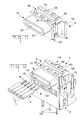
- the connector 2 comprises a one piece molded female insulating housing 4, having wire receiving electrical terminals 6 secured therein, and a one piece molded male insulating housing 8 for mating with the housing 4.
- the female housing 4 comprises a base 10 having through, terminal receiving slots 12 therein front and rear side walls, 14 and 16, respectively, and opposite end walls 18, upstanding from the base 10.
- the walls 14, 16 and 18 cooperate with the base 10 to define an elongate socket 20.
- the rear side wall 16 comprises an upstanding resilient latch arm 17 having a latching shoulder 19.
- Each terminal 6, which has been stamped and formed from a single piece of sheet metal stock is uniplanar and is of rectangular cross section.
- Each terminal 6 comprises a pin 22, extending from one side of a substantially square anchoring part 24 from the opposite side of which projects a neck 26 supporting a slotted, resilient wire receiving part 30.
- the part 30 comprises a bight 32 connecting a pair of arms 28, parts 34 of which converge towards each other in a direction away from the bight 32 and which, at their position of closest convergence merge at junctions 35 with upper, parallel parts 36 of the arms 28 terminating in chamfered surfaces 38 defining a wire guiding mouth 40.
- Inner faces of the arms 28, cooperate to define a slot having a part 42 tapering away from the neck 26 and adjoining a narrow rectilinear wire receiving part 44 of the slot.
- the opposite planar inner faces of the parts 36 of the arms 28 cooperate to provide final wire contact surfaces 37 immediately adjacent to the parts 34 of the arms 28.
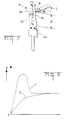
- Each arm 38 has a lever length 11 between its chamfered surface 38 and the bottom of the bight 32, the length 12 between the contact surfaces 37 and the bottom of the bight 32 being greatly shorter than the length 11 as will be apparent from Figure 6.
- the arms 28 are capable of resilient torsional movement about their junctions with the bight 32.
- the ratio of the lengths 11 and 12 is approximately 4:2.5.
- the male housing 8 comprises an elongate block 46 having a row of five wire receiving passages 48 (only one of which is shown in Figure 1) extending in parallel relationship from a transverse wire receiving channel 50 defined by a hood 51 projecting forwardly from the block 46 and having an enlarged insulating receiving mouth 52 opening into a forward face 53 of the hood 51.
- a respective one of five terminal arm receiving slots 56 extending perpendicularly to the passages 48 and each opening both into a top face 58 of the block 46 and a bottom face 60 thereof.
- the block 46 has on a rear face 64 thereof, opposite to the hood 51, a latch member 66 resting on the top of the latch arm 17 for subsequent latching under the latching shoulder 19 of the latch arm 17 of the female housing 4.
- each slot 56 has therein a pair of abutment shoulders 68, the shoulder 68 being located on each side of the respective passage 48 with which the slot 56 communicates the shoulders 68 being provided where the terminals and according to the embodiment of Figure 9.
- the male housing 8 is located in the female housing 4 in an initial position shown in Figure 1 with the hollow plug 62 of the housing 8 partially inserted into the socket 20 of the housing 4.
- each terminal 6 During the insertion of the plug 62, the arms 28 of each terminal 6 enter a respective slot 56 of the housing 8, so that, initially, as shown in Figure 6, the wire W in its passage 48 is forced into the rectilinear wire receiving part 44 of the slot of the terminal 6, guided by the chamfered surfaces 38 thereof.
- the wire W As the plug 62 is pushed home into the socket 20, the wire W is forced down between the parts 36 of the arms 28 of the respective terminal 6 until, as shown in Figure 7, wire W reaches the final wire contact surfaces 37, at which time the plug 62 bottoms on the base 10 of the socket 20 so that the wire W is retained in its final position between the contact surfaces 37 of the arms 28.
- Each wire W is thereby securely galvanically connected to a respective one of the terminals 6.
- the ordinate represents the contact force F exerted by the arms 28 against the inserted wire W and the abscissa represents the insertion depth D of the wire W between the arms 28.
- the curve X indicates the wire insertion characteristic of a terminal 6, whereas the curve Y indicates the wire insertion characteristic of a conventional bare wire receiving terminal 6a shown in Figure 4.
- the curve X rises gradually and does not peak so that the force needed to insert the housing 8 fully into the housing 4 is desirably low, which is of considerable advantage given that five wires W need to be inserted simultaneously into respective terminals 6.
- the curve Y rises initially very steeply as the wire is forced down between the arms 28a.
- the arms 28′ have been pretorsioned during manufacture of the terminal, about their parts 38′ so that their parts 36′ are angled with respect to each other. If a lead L is accidentally pulled in the direction of the arrow C in Figures 3 and 9, the galvanic connection between the wire W and the arms 28′ will still be maintained, since, as will appear from Figures 3 and 9, arms 28′ will be torsioned resiliently about their junctions with the bight 32 as shown in Figure 9, whereby the parts 36′ of the arms 28′ will be swung about their longitudinal axes Z as indicated by the arrows E in Figure 3, so as to engage against the shoulders 68 in the respective passage 48, whereby corners of the parts 36′ of the arms 28′ of the terminals 6 are driven against the wire W. Upon the tension on the wire W being released, the parts 36′ will be returned to their initial positions by virtue of the natural resilience of the arms 28′.
- the rear side wall 16 of the housing 4 comprises two end portions 70 between which the latch arm 17 upstands beyond them.
- the latching shoulder 19 is provided by the upper end of a vertical slot in the arm 17.
- Each side wall being provided by the upper end of a vertical slot in the arm 17.
- Each side wall 18 is in the form of a further latch arm, having a central vertical slot, the upper end of which provides a latching shoulder 72.
- the five terminals 6 are arranged in an array comprising a front row of three terminals 6 and a rear row of two terminals 6.
- Each side wall 18 is separated from the adjacent rear wall portion 70 by a vertical keyway 74, the bottom of which is provided by the base 10 of the housing 4.
- a latch member 76 (only one of which is shown) and rearwardly of the latch member 76 a vertical key 78 extending over the full height of the block 46 and the plug 62.
- the slots 56 are arranged in the same array as the terminals 6, namely an array comprising a front row of three slots 56 and rear row of two slots 56.
- the housing 8 is of substantially the same length as the distance between the side walls 18 of the housing 4, that is to say of substantially the same length of the socket 20.
- the latch member 66 engages against the upper edge of the latch arm 17, each key 78 of the housing 8 engaging in a respective keyway 74 of the housing 4, each latch member 76 of the housing 8 engaging against the latching shoulder 72 of a respective side wall 18.
- the housing is stabilized in the housing 4 by the engagement of the keys 78 in the keways 74.
- the side walls 18 are spread resiliently part by the latch members 76 of the housing 8 and then resile as the latch members 76 pass the shoulders 72, whereby the housing 8 is captive in the housing 4.
- FIG 13 shows the wires W when they have been inserted in the direction of the arrow A in Figures 1 and 12, into the wire receiving passages 48, with the insulation I of the leads L received in the hood 51. As shown in Figure 13, in said initial position, each wire W lies just above the mouth 40 of a respective one of the terminal 6.
- Figure 14 shows the connector 2 when the housing 8 has been fully depressed in the direction of the arrow B in Figure 1, guided by the engagement of the keys 78 in the keyways 74, so that each wire W lies between the contact surfaces 37 of the respective terminal 6, the latch member 66 being engaged against the shoulder 19 of the latch arm 17.
- the housing 8 can be withdrawn from the housing 4 back to its initial position, by manually pulling back the latch arm 17 in the direction of the arrow X, while simultaneously withdrawing the housing 8 in the direction of the arrow Y, thereby disconnecting wires on the terminals 6.
- the connector 2 can accordingly act as a switch, aided by the soft spring characteristics of the arms 28 of the terminals 6.
- the connector 2 is, therefore, suitable for use in an apparatus, for example domestic television or video apparatus, in which circuits are required to be broken when the apparatus is serviced.
Landscapes
- Details Of Connecting Devices For Male And Female Coupling (AREA)
- Connector Housings Or Holding Contact Members (AREA)
- Connections By Means Of Piercing Elements, Nuts, Or Screws (AREA)
- Multi-Conductor Connections (AREA)
- Coupling Device And Connection With Printed Circuit (AREA)
Applications Claiming Priority (2)
| Application Number | Priority Date | Filing Date | Title |
|---|---|---|---|
| GB909026529A GB9026529D0 (en) | 1990-12-06 | 1990-12-06 | An electrical wire connector and an electrical terminal therefor |
| GB9026529 | 1990-12-06 |
Publications (3)
| Publication Number | Publication Date |
|---|---|
| EP0489549A2 true EP0489549A2 (de) | 1992-06-10 |
| EP0489549A3 EP0489549A3 (en) | 1992-08-26 |
| EP0489549B1 EP0489549B1 (de) | 1996-01-31 |
Family
ID=10686578
Family Applications (1)
| Application Number | Title | Priority Date | Filing Date |
|---|---|---|---|
| EP91311083A Expired - Lifetime EP0489549B1 (de) | 1990-12-06 | 1991-11-29 | Elektrischer Drahtverbinder |
Country Status (7)
| Country | Link |
|---|---|
| US (1) | US5190470A (de) |
| EP (1) | EP0489549B1 (de) |
| JP (1) | JPH04277471A (de) |
| KR (1) | KR920013816A (de) |
| DE (1) | DE69116833T2 (de) |
| GB (1) | GB9026529D0 (de) |
| IE (1) | IE74165B1 (de) |
Cited By (8)
| Publication number | Priority date | Publication date | Assignee | Title |
|---|---|---|---|---|
| EP0592101A1 (de) * | 1992-10-07 | 1994-04-13 | The Whitaker Corporation | Elektrischer Verbinder mit verbesserter Zugentlastung |
| FR2730095A1 (fr) * | 1995-02-01 | 1996-08-02 | Beromet | Dispositif de connexion a auto-denudage |
| EP0734095A1 (de) * | 1995-03-23 | 1996-09-25 | Lk A/S | Elektrische Verbinderanordnung, Verlängerungsverbindern und System für die elektrische Leistungsversorgung |
| EP0856911A1 (de) * | 1997-01-30 | 1998-08-05 | Ria Electronic Albert Metz | Mehrpolige Anschlussklemme |
| WO2006091554A1 (en) * | 2005-02-22 | 2006-08-31 | Tyco Electronics Corporation | Low profile surface mount connector |
| EP1801915A1 (de) * | 2005-12-23 | 2007-06-27 | INARCA S.p.A. | Verbinder zur Verbindung elektrischen Drähte mit elektronischen Karten, insbesondere für Verdrahtung im Hausnetz. |
| US7513793B2 (en) | 2006-12-22 | 2009-04-07 | Tyco Electronics Corporation | Surface mount poke in connector |
| CN103138064A (zh) * | 2011-11-29 | 2013-06-05 | Abb瑞士有限公司 | 用于平带式缆线的联接装置和带有平带式缆线的电气装置 |
Families Citing this family (10)
| Publication number | Priority date | Publication date | Assignee | Title |
|---|---|---|---|---|
| GB9313281D0 (en) * | 1993-06-28 | 1993-08-11 | Amp Gmbh | Sealed insulation displacement connector |
| US6050845A (en) * | 1997-11-20 | 2000-04-18 | The Whitaker Corporation | Electrical connector for terminating insulated conductors |
| JP2001102118A (ja) * | 1999-10-01 | 2001-04-13 | Sumitomo Wiring Syst Ltd | フラットケーブル用コネクタ、フラットケーブル用コネクタに用いられる端子金具及びフラットケーブル用コネクタに用いられる端子金具の製造方法 |
| EP1337009B1 (de) * | 2002-02-15 | 2005-05-04 | Sumitomo Wiring Systems, Ltd. | Geschirmter Steckverbinder, geschirmtes Steckverbindersystem, Kontakteinsatz und Verwendung desselben |
| DE102004054203A1 (de) * | 2004-11-10 | 2006-05-11 | Erni Elektroapparate Gmbh | Schneidklemm-Steckkontaktleiste für elektrische Steckverbinder |
| DE102010009169A1 (de) * | 2010-02-24 | 2011-08-25 | Phoenix Contact GmbH & Co. KG, 32825 | Steckverbinderanordnung |
| US9419361B2 (en) * | 2014-09-23 | 2016-08-16 | Tyco Electronics Corporation | Electrical connector with pivot block for terminating an electrical wire |
| US10276955B2 (en) * | 2017-03-31 | 2019-04-30 | Avx Corporation | Electrical connector |
| CN112864680A (zh) * | 2019-11-11 | 2021-05-28 | 唐虞企业股份有限公司 | 电连接器组 |
| DE202019106609U1 (de) * | 2019-11-27 | 2021-03-02 | Wago Verwaltungsgesellschaft Mbh | Leiteranschlussklemme zum Anschließen eines elektrischen Leiters |
Family Cites Families (10)
| Publication number | Priority date | Publication date | Assignee | Title |
|---|---|---|---|---|
| US3012219A (en) * | 1959-03-19 | 1961-12-05 | Minnesota Mining & Mfg | Solderless connector for insulated small wires |
| US4496207A (en) * | 1977-08-12 | 1985-01-29 | E. I. Du Pont De Nemours And Company | Electrical connector with dual position latches |
| GB2002599B (en) * | 1977-08-12 | 1982-03-17 | Du Pont | Electrical connector |
| US4431246A (en) * | 1981-04-09 | 1984-02-14 | Akzona Incorporated | Insulation piercing contact |
| CA1162264A (en) * | 1981-10-05 | 1984-02-14 | Northern Telecom Limited | Connectors with insulation-displacing terminals |
| US4435034A (en) * | 1981-10-08 | 1984-03-06 | Northern Telecom Limited | Connectors with insulation-displacing terminals |
| US4533198A (en) * | 1983-08-15 | 1985-08-06 | International Telephone & Telegraph Corp. | Insulation displacement connector |
| US4652070A (en) * | 1985-10-18 | 1987-03-24 | Reliance Electric Company | Insulation displacement connector terminal block |
| US4741707A (en) * | 1986-02-19 | 1988-05-03 | Woven Electronics Corporation | Method and woven cable termination with insulation displaceable connector |
| DE3915611C1 (en) * | 1989-05-12 | 1990-06-13 | Stocko Metallwarenfabriken Henkels Und Sohn Gmbh & Co, 5600 Wuppertal, De | Electrical plug and socket connector - has contact units with contact springs engaging socket suits |
-
1990
- 1990-12-06 GB GB909026529A patent/GB9026529D0/en active Pending
-
1991
- 1991-11-07 IE IE388691A patent/IE74165B1/en not_active IP Right Cessation
- 1991-11-22 US US07/797,494 patent/US5190470A/en not_active Expired - Fee Related
- 1991-11-29 DE DE69116833T patent/DE69116833T2/de not_active Expired - Fee Related
- 1991-11-29 EP EP91311083A patent/EP0489549B1/de not_active Expired - Lifetime
- 1991-12-06 JP JP3322889A patent/JPH04277471A/ja not_active Withdrawn
- 1991-12-06 KR KR1019910022325A patent/KR920013816A/ko not_active Withdrawn
Cited By (13)
| Publication number | Priority date | Publication date | Assignee | Title |
|---|---|---|---|---|
| EP0592101A1 (de) * | 1992-10-07 | 1994-04-13 | The Whitaker Corporation | Elektrischer Verbinder mit verbesserter Zugentlastung |
| US5516984A (en) * | 1992-10-07 | 1996-05-14 | The Whitaker Corporation | Electrical connector having improved strain relief |
| FR2730095A1 (fr) * | 1995-02-01 | 1996-08-02 | Beromet | Dispositif de connexion a auto-denudage |
| EP0734095A1 (de) * | 1995-03-23 | 1996-09-25 | Lk A/S | Elektrische Verbinderanordnung, Verlängerungsverbindern und System für die elektrische Leistungsversorgung |
| EP0856911A1 (de) * | 1997-01-30 | 1998-08-05 | Ria Electronic Albert Metz | Mehrpolige Anschlussklemme |
| US5951321A (en) * | 1997-01-30 | 1999-09-14 | Ria Electronic Albert Metz | Multipin connector assembly |
| WO2006091554A1 (en) * | 2005-02-22 | 2006-08-31 | Tyco Electronics Corporation | Low profile surface mount connector |
| US7309252B2 (en) | 2005-02-22 | 2007-12-18 | Tyco Electronics Corporation | Low profile surface mount connector |
| EP1801915A1 (de) * | 2005-12-23 | 2007-06-27 | INARCA S.p.A. | Verbinder zur Verbindung elektrischen Drähte mit elektronischen Karten, insbesondere für Verdrahtung im Hausnetz. |
| US7270564B1 (en) | 2005-12-23 | 2007-09-18 | Inarca S.P.A. | Connector for connecting electrical wires to electronic boards in domotic networks |
| US7513793B2 (en) | 2006-12-22 | 2009-04-07 | Tyco Electronics Corporation | Surface mount poke in connector |
| CN103138064A (zh) * | 2011-11-29 | 2013-06-05 | Abb瑞士有限公司 | 用于平带式缆线的联接装置和带有平带式缆线的电气装置 |
| EP2600470A1 (de) * | 2011-11-29 | 2013-06-05 | ABB Schweiz AG | Anschlussvorrichtung für ein Flachbandkabel und elektrisches Gerät mit angeschlossenem Flachbandkabel |
Also Published As
| Publication number | Publication date |
|---|---|
| IE913886A1 (en) | 1992-06-17 |
| GB9026529D0 (en) | 1991-01-23 |
| US5190470A (en) | 1993-03-02 |
| JPH04277471A (ja) | 1992-10-02 |
| IE74165B1 (en) | 1997-07-02 |
| EP0489549B1 (de) | 1996-01-31 |
| DE69116833D1 (de) | 1996-03-14 |
| KR920013816A (ko) | 1992-07-29 |
| EP0489549A3 (en) | 1992-08-26 |
| DE69116833T2 (de) | 1996-09-26 |
Similar Documents
| Publication | Publication Date | Title |
|---|---|---|
| US5190470A (en) | Electrical wire connector and an electrical terminal therefor | |
| US5004436A (en) | Electrical connector | |
| US4566749A (en) | Electrical connector receptacle | |
| EP0653811B1 (de) | Elektrischer Verbinder mit Zugentlastung | |
| US4053197A (en) | Electrical connector | |
| US6454611B1 (en) | Surface mountable electrical connector system | |
| US4405193A (en) | Preloaded electrical connector | |
| JPH0782892B2 (ja) | ドロワコネクター | |
| EP0817313A2 (de) | Elektrischer Schneidklemmenverbinderanordnung mit Kabelklemmvorrichtung | |
| US4653831A (en) | Connector housing | |
| JPS6213795B2 (de) | ||
| EP0527399A1 (de) | Schneidklemmkontakt | |
| US4439001A (en) | IDC Socket connector | |
| EP0746057A1 (de) | Lagersicherungsvorrichtung der Endkontakte eines elektrischen Verbinders | |
| GB2294817A (en) | Electrical terminal and connector assembly | |
| EP0644609B1 (de) | Flacher Schneidklemmkontakt für elektrische Verbinder | |
| US5672075A (en) | Round terminal-receiving connector | |
| US4946406A (en) | Electrical connector which requires no application tool | |
| US5252094A (en) | Electrical connector with improved terminal retention | |
| US4863400A (en) | Electrical connector | |
| US20040175982A1 (en) | Plug connector housing with locking mechanism and plug connector with locking mechanism using thereof | |
| US4780092A (en) | Electrical connector | |
| EP0446220B1 (de) | Elektrischer verbinder | |
| EP0729201A1 (de) | Elektrischer Verbinder mit Kontaktverriegelungsvorrichtung | |
| US5356307A (en) | Insulation displacement electrical connector system |
Legal Events
| Date | Code | Title | Description |
|---|---|---|---|
| PUAI | Public reference made under article 153(3) epc to a published international application that has entered the european phase |
Free format text: ORIGINAL CODE: 0009012 |
|
| AK | Designated contracting states |
Kind code of ref document: A2 Designated state(s): DE FR GB IT NL |
|
| PUAL | Search report despatched |
Free format text: ORIGINAL CODE: 0009013 |
|
| AK | Designated contracting states |
Kind code of ref document: A3 Designated state(s): DE FR GB IT NL |
|
| RAP1 | Party data changed (applicant data changed or rights of an application transferred) |
Owner name: THE WHITAKER CORPORATION |
|
| 17P | Request for examination filed |
Effective date: 19930128 |
|
| 17Q | First examination report despatched |
Effective date: 19940830 |
|
| GRAA | (expected) grant |
Free format text: ORIGINAL CODE: 0009210 |
|
| AK | Designated contracting states |
Kind code of ref document: B1 Designated state(s): DE FR GB IT NL |
|
| ITF | It: translation for a ep patent filed | ||
| REF | Corresponds to: |
Ref document number: 69116833 Country of ref document: DE Date of ref document: 19960314 |
|
| ET | Fr: translation filed | ||
| PLBE | No opposition filed within time limit |
Free format text: ORIGINAL CODE: 0009261 |
|
| STAA | Information on the status of an ep patent application or granted ep patent |
Free format text: STATUS: NO OPPOSITION FILED WITHIN TIME LIMIT |
|
| 26N | No opposition filed | ||
| PGFP | Annual fee paid to national office [announced via postgrant information from national office to epo] |
Ref country code: NL Payment date: 19980914 Year of fee payment: 8 |
|
| PG25 | Lapsed in a contracting state [announced via postgrant information from national office to epo] |
Ref country code: NL Free format text: LAPSE BECAUSE OF NON-PAYMENT OF DUE FEES Effective date: 20000601 |
|
| NLV4 | Nl: lapsed or anulled due to non-payment of the annual fee |
Effective date: 20000601 |
|
| PGFP | Annual fee paid to national office [announced via postgrant information from national office to epo] |
Ref country code: GB Payment date: 20001004 Year of fee payment: 10 |
|
| PGFP | Annual fee paid to national office [announced via postgrant information from national office to epo] |
Ref country code: FR Payment date: 20001107 Year of fee payment: 10 |
|
| PG25 | Lapsed in a contracting state [announced via postgrant information from national office to epo] |
Ref country code: GB Free format text: LAPSE BECAUSE OF NON-PAYMENT OF DUE FEES Effective date: 20011129 |
|
| REG | Reference to a national code |
Ref country code: GB Ref legal event code: IF02 |
|
| GBPC | Gb: european patent ceased through non-payment of renewal fee |
Effective date: 20011129 |
|
| PG25 | Lapsed in a contracting state [announced via postgrant information from national office to epo] |
Ref country code: FR Free format text: LAPSE BECAUSE OF NON-PAYMENT OF DUE FEES Effective date: 20020730 |
|
| REG | Reference to a national code |
Ref country code: FR Ref legal event code: ST |
|
| REG | Reference to a national code |
Ref country code: FR Ref legal event code: ST |
|
| PGFP | Annual fee paid to national office [announced via postgrant information from national office to epo] |
Ref country code: DE Payment date: 20021127 Year of fee payment: 12 |
|
| PG25 | Lapsed in a contracting state [announced via postgrant information from national office to epo] |
Ref country code: DE Free format text: LAPSE BECAUSE OF NON-PAYMENT OF DUE FEES Effective date: 20040602 |
|
| PG25 | Lapsed in a contracting state [announced via postgrant information from national office to epo] |
Ref country code: IT Free format text: LAPSE BECAUSE OF NON-PAYMENT OF DUE FEES;WARNING: LAPSES OF ITALIAN PATENTS WITH EFFECTIVE DATE BEFORE 2007 MAY HAVE OCCURRED AT ANY TIME BEFORE 2007. THE CORRECT EFFECTIVE DATE MAY BE DIFFERENT FROM THE ONE RECORDED. Effective date: 20051129 |