EP0592101A1 - Elektrischer Verbinder mit verbesserter Zugentlastung - Google Patents
Elektrischer Verbinder mit verbesserter Zugentlastung Download PDFInfo
- Publication number
- EP0592101A1 EP0592101A1 EP93306962A EP93306962A EP0592101A1 EP 0592101 A1 EP0592101 A1 EP 0592101A1 EP 93306962 A EP93306962 A EP 93306962A EP 93306962 A EP93306962 A EP 93306962A EP 0592101 A1 EP0592101 A1 EP 0592101A1
- Authority
- EP
- European Patent Office
- Prior art keywords
- housing
- strain relief
- insulating housing
- cover
- recited
- Prior art date
- Legal status (The legal status is an assumption and is not a legal conclusion. Google has not performed a legal analysis and makes no representation as to the accuracy of the status listed.)
- Granted
Links
- 238000009413 insulation Methods 0.000 claims abstract description 5
- 239000004020 conductor Substances 0.000 claims description 28
- 230000008878 coupling Effects 0.000 claims description 2
- 238000010168 coupling process Methods 0.000 claims description 2
- 238000005859 coupling reaction Methods 0.000 claims description 2
- 230000013011 mating Effects 0.000 abstract description 6
- 238000010276 construction Methods 0.000 abstract 1
- 230000037431 insertion Effects 0.000 description 1
- 238000003780 insertion Methods 0.000 description 1
Images


Classifications
-
- H—ELECTRICITY
- H01—ELECTRIC ELEMENTS
- H01R—ELECTRICALLY-CONDUCTIVE CONNECTIONS; STRUCTURAL ASSOCIATIONS OF A PLURALITY OF MUTUALLY-INSULATED ELECTRICAL CONNECTING ELEMENTS; COUPLING DEVICES; CURRENT COLLECTORS
- H01R13/00—Details of coupling devices of the kinds covered by groups H01R12/70 or H01R24/00 - H01R33/00
- H01R13/62—Means for facilitating engagement or disengagement of coupling parts or for holding them in engagement
- H01R13/639—Additional means for holding or locking coupling parts together, after engagement, e.g. separate keylock, retainer strap
-
- H—ELECTRICITY
- H01—ELECTRIC ELEMENTS
- H01R—ELECTRICALLY-CONDUCTIVE CONNECTIONS; STRUCTURAL ASSOCIATIONS OF A PLURALITY OF MUTUALLY-INSULATED ELECTRICAL CONNECTING ELEMENTS; COUPLING DEVICES; CURRENT COLLECTORS
- H01R13/00—Details of coupling devices of the kinds covered by groups H01R12/70 or H01R24/00 - H01R33/00
- H01R13/58—Means for relieving strain on wire connection, e.g. cord grip, for avoiding loosening of connections between wires and terminals within a coupling device terminating a cable
- H01R13/582—Means for relieving strain on wire connection, e.g. cord grip, for avoiding loosening of connections between wires and terminals within a coupling device terminating a cable the cable being clamped between assembled parts of the housing
- H01R13/5829—Means for relieving strain on wire connection, e.g. cord grip, for avoiding loosening of connections between wires and terminals within a coupling device terminating a cable the cable being clamped between assembled parts of the housing the clamping part being flexibly or hingedly connected to the housing
-
- H—ELECTRICITY
- H01—ELECTRIC ELEMENTS
- H01R—ELECTRICALLY-CONDUCTIVE CONNECTIONS; STRUCTURAL ASSOCIATIONS OF A PLURALITY OF MUTUALLY-INSULATED ELECTRICAL CONNECTING ELEMENTS; COUPLING DEVICES; CURRENT COLLECTORS
- H01R12/00—Structural associations of a plurality of mutually-insulated electrical connecting elements, specially adapted for printed circuits, e.g. printed circuit boards [PCB], flat or ribbon cables, or like generally planar structures, e.g. terminal strips, terminal blocks; Coupling devices specially adapted for printed circuits, flat or ribbon cables, or like generally planar structures; Terminals specially adapted for contact with, or insertion into, printed circuits, flat or ribbon cables, or like generally planar structures
- H01R12/70—Coupling devices
- H01R12/77—Coupling devices for flexible printed circuits, flat or ribbon cables or like structures
- H01R12/771—Details
- H01R12/772—Strain relieving means
Definitions
- This invention relates to an electrical connector, and more particularly, it relates to an electrical connector comprising an insulating housing having a housing member for receiving a cover having strain relief means for relieving strain on the plurality of insulated conductors which are inserted into the insulating housing.
- European Patent Application No. 91 311 083.9 discloses an electrical wire connector 2 comprising a one-piece molded female insulating housing 4, having wire receiving electrical terminal 6 secured therein, and a one-piece molded male insulating housing 8 for mating with the housing 4.
- the male housing 8 has a row of wire receiving passageways 48 each intersecting a slot 56 in the male housing 8.
- the slot 56 receives the wire receiving part 30 of a respective terminal 6 when the male housing 8 has been fully inserted into the female housing 4.
- Wires (W) previously inserted into the wire receiving passages 48 are forced into the wire receiving slots 44 of the terminals 6 during the insertion of the male housing 8 into the female housing 4.
- An object of this invention is to provide an electrical connector having improved strain relief for relieving strain on a plurality of insulated conductors which are terminated in the electrical connector.
- Another object of this invention is to provide an insulating housing for mounting in a female connector housing, whereby the insulating housing comprises a cover member which is mounted on a housing member and which comprises strain relief means integrally formed as part of the cover.
- Still another object of this invention is to provide an electrical connector comprising an insulating housing having a cover with an integrally formed strain relief comprising a plurality of teeth for engaging the insulation on a plurality of insulated conductors which are inserted into the insulating housing.
- this invention comprises an insulating housing for coupling to a female connector housing having a plurality of electrical terminals, said insulating housing comprising a housing member; a cover for mounting on said housing member, said housing member and said cover each having a plurality of slots for receiving said plurality of electrical terminals; and strain relief means associated with said cover for securing a plurality of insulated conductors in operative relationship with said plurality of slots and also for relieving strain on said plurality of insulated conductors.
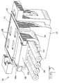
- Fig. 1 shows an assembled view of an insulating housing, hereinafter designated insulating housing 10, for mounting in a mating female connector housing (not shown) of an electrical connector (not shown).
- the electrical connector is of the type shown and described in European Patent Application No. 91 311 083.9, (Publication No 0 489 549) which is hereby incorporated by reference and made a part hereof.
- the insulating housing 10 comprises a housing member 12 and a cover member 14 which is detachably mounted in an opening 16 in housing member 12.
- the housing member 12 and cover member 14 each comprise a plurality of slots 18 for receiving a plurality of terminals (not shown) which are located in the female connector housing (not shown).
- the insulating housing 12 comprises a plurality of wire receiving openings 20 each being capable of receiving a conductor 22 of an insulated wire 24.
- the wire receiving openings 20 are operatively aligned with the terminal receiving slots 18 such that the conductors 22 are operatively aligned in the terminal receiving slots 18 when the insulated wires 24 are inserted into wire receiving openings 20.
- the insulating housing 10 may be inserted into the female connector housing (not shown) so that the conductors 22 operatively engage the terminals (not shown) in the female connector housing (not shown) in the manner described in European Patent Application No. 91 311 083.9.
- housing member 12 comprises a generally U-shaped shroud 34 for receiving the conductors 22 and also for facilitating guiding the conductors 22 into the wire receiving opening 20.
- the insulating housing 10 also comprises strain relief means 26 (Figs. 1-3) associated with the cover 14 for securing the plurality of insulated conductors in operative relationship with the plurality of terminal receiving slots 18.
- the strain relief means also functions to relieve strain on the plurality of insulated conductors 24 so that, for example, the electrical connection between the conductors 22 and the terminals (not shown) in the female connector housing (not shown) will not be interrupted if the insulated conductors 24 are pulled.
- the strain relief means 26 is integrally formed as part of cover 14 and comprises a strain relief member 28 having a first end 28a and a second end 28b. The first end 28a is pivotally secured to cover 14.
- strain relief means 26 comprises a plurality of teeth 30 located on second end 28b of strain relief member 28.
- the plurality of teeth 30 bite into insulation 32 of insulated wires 24 in order to secure the plurality of conductors 22 securely in the insulating housing 10.
- the strain relief member 28 is pivotally secured to cover 14 such that it can pivot from an open position (shown in Fig. 4) to a closed position (shown in Fig. 5).
- shroud 34 cooperates with strain relief member 28 to define an opening 36 (Fig. 1) when strain relief member 28 is in the open position.
- the insulated wires 24 may be guided into opening 36 until each conductor 22 is inserted into its respective wire receiving opening 20, whereupon strain relief member 28 may be rotated in the direction of arrow A in Fig. 4 until strain relief member 28 has been fully pivoted to the locked position shown in Fig. 5.
- insulating housing 10 comprises locking means for locking strain relief member 28 in the locked position shown in Fig. 5.
- locking means comprises a plurality of resilient detents 38 (Figs. 1, 4 and 5) located on shroud 34.
- Locking means also comprises a plurality of notched out portions 40 which cooperate with the resilient detents 38 to retain strain relief member 28 in the locked position.
- the plurality of resilient detents 38 each comprise a beveled surface 38a.
- cover 14 comprises a pair of latches 42 which operate to latch or secure cover 14 in housing member 12 when cover 14 is inserted into aperture 16.
- the insulated wires 24 and conductors 22 may be inserted into opening 36 in the manner described previously herein.
- Strain relief member 28 may then be pivoted to the locked position shown in Fig. 5, thereby causing the plurality of teeth 30 to bite into insulation 32 of insulated wires 24 which, in turn, causes insulated wires 24 to be firmly secured to insulated housing 10.
- insulating housing 10 may then be mounted or inserted into the mating female connector housing (not shown), thereby causing conductors 22 to be terminated in the terminals (not shown) of the female connector housing (not shown).
- the manner of operation, assembly, and mounting of the insulating housing 10 into the female connector housing (not shown) of an electrical connector (not shown) is substantially similar to that described and shown European Patent Application No. 91 311 083.9, (Publication No 0 489 549) which was mentioned earlier herein.
- this insulating housing 10 has improved strain relief means 26 for relieving strain on the insulated wires 24 such that when the insulating housing 10 is mounted into a mating female connector housing (not shown), the electrical connection between the insulating housing 10 and its mating female connector housing will not be interrupted.
Landscapes
- Details Of Connecting Devices For Male And Female Coupling (AREA)
- Connections By Means Of Piercing Elements, Nuts, Or Screws (AREA)
- Multi-Conductor Connections (AREA)
Applications Claiming Priority (2)
| Application Number | Priority Date | Filing Date | Title |
|---|---|---|---|
| GB9221103 | 1992-10-07 | ||
| GB929221103A GB9221103D0 (en) | 1992-10-07 | 1992-10-07 | Electrical connector having improved strain relief |
Publications (2)
| Publication Number | Publication Date |
|---|---|
| EP0592101A1 true EP0592101A1 (de) | 1994-04-13 |
| EP0592101B1 EP0592101B1 (de) | 1997-07-23 |
Family
ID=10723111
Family Applications (1)
| Application Number | Title | Priority Date | Filing Date |
|---|---|---|---|
| EP93306962A Expired - Lifetime EP0592101B1 (de) | 1992-10-07 | 1993-09-02 | Elektrischer Verbinder mit verbesserter Zugentlastung |
Country Status (7)
| Country | Link |
|---|---|
| US (1) | US5516984A (de) |
| EP (1) | EP0592101B1 (de) |
| JP (1) | JPH06196220A (de) |
| KR (1) | KR940010416A (de) |
| DE (1) | DE69312418T2 (de) |
| GB (1) | GB9221103D0 (de) |
| MY (1) | MY110115A (de) |
Cited By (10)
| Publication number | Priority date | Publication date | Assignee | Title |
|---|---|---|---|---|
| WO1998033246A1 (en) * | 1997-01-29 | 1998-07-30 | Ut Automotive Dearborn, Inc. | Method for connecting flat flexible cable and a connector |
| EP0952630A3 (de) * | 1998-04-22 | 2000-08-02 | Molex Incorporated | Elektrischer Verbinder für flache flexible Schaltungen |
| EP0926775A3 (de) * | 1997-12-19 | 2000-08-16 | VERDA s.r.l. | Gehäuse für elektrische Verbinder |
| FR2798229A1 (fr) * | 1999-09-07 | 2001-03-09 | Framatome Connectors Int | Perfectionnement aux connecteurs pour circuit souple |
| GB2372890A (en) * | 1998-07-08 | 2002-09-04 | R W Data Ltd | Gripping of electrical cables |
| DE10119870A1 (de) * | 2001-04-24 | 2002-11-21 | Tyco Electronics Amp Gmbh | Kontaktleiste |
| DE10153725B4 (de) * | 2000-10-31 | 2005-11-24 | Yazaki Corp. | Struktur zum Herausführen flexibler Leiterelemente |
| DE102008026470A1 (de) * | 2008-06-03 | 2010-02-04 | Bticino S.P.A. | Druckstück für eine Anschlussklemme |
| WO2013092570A1 (de) * | 2011-12-22 | 2013-06-27 | Phoenix Contact Gmbh & Co Kg | Elektrischer verbinder |
| EP3118936A1 (de) * | 2015-07-17 | 2017-01-18 | Wago Verwaltungsgesellschaft mbH | Steckverbinder und verformungswerkzeug hierzu |
Families Citing this family (23)
| Publication number | Priority date | Publication date | Assignee | Title |
|---|---|---|---|---|
| DE19527123A1 (de) * | 1995-07-25 | 1997-01-30 | Bosch Gmbh Robert | Verfahren zur elektrischen Verbindung zweier elektrischer Bauteile miteinander |
| US5892659A (en) * | 1995-12-12 | 1999-04-06 | The Whitaker Corporation | Retention system for solenoid coils |
| US6083052A (en) * | 1998-03-23 | 2000-07-04 | The Siemon Company | Enhanced performance connector |
| JP2000231961A (ja) * | 1998-12-08 | 2000-08-22 | Sumitomo Wiring Syst Ltd | コネクタ |
| US6368143B1 (en) | 1999-02-12 | 2002-04-09 | The Siemon Company | Modular plug with two piece housing |
| EP1198867B1 (de) | 1999-07-27 | 2004-03-31 | The Siemon Company | Abgeschirmter telekommunikationsstecker |
| EP1182736A3 (de) * | 2000-05-29 | 2002-08-21 | TALLER Automotive GmbH | Verbindungsanordnung für Flexfolien |
| US6506077B2 (en) | 2000-07-21 | 2003-01-14 | The Siemon Company | Shielded telecommunications connector |
| FR2814864B1 (fr) * | 2000-10-02 | 2005-01-14 | Fci Automotive France | Dispositif de maintien des zones de sertissage d'un circuit souple dans un connecteur electrique et le connecteur equipe |
| AU2005337047A1 (en) * | 2004-10-14 | 2007-04-12 | Recopharma Ab | Composition and methods for inhibiting H. pylori adhesion and infection |
| DE102006028202A1 (de) * | 2006-06-20 | 2007-12-27 | Tyco Electronics Amp Gmbh | Elektrischer Steckverbinder |
| CN101656370B (zh) * | 2009-09-15 | 2011-09-14 | 深圳亚力盛连接器有限公司 | 线束连接器 |
| CN102157832B (zh) * | 2011-04-13 | 2013-11-13 | 深圳亚力盛连接器有限公司 | 线束连接器 |
| JP6073373B2 (ja) | 2012-02-07 | 2017-02-01 | スリーエム イノベイティブ プロパティズ カンパニー | ワイヤマウント電気コネクタ |
| US9509094B2 (en) | 2012-02-07 | 2016-11-29 | 3M Innovative Properties Company | Board mount electrical connector with latch opening on bottom wall |
| US9553401B2 (en) | 2012-02-07 | 2017-01-24 | 3M Innovative Properties Company | Electrical connector for strain relief for an electrical cable |
| US9455503B2 (en) | 2012-02-07 | 2016-09-27 | 3M Innovative Properties Company | Electrical connector contact terminal |
| EP2812951A4 (de) | 2012-02-07 | 2015-10-28 | 3M Innovative Properties Co | Sperre für einen elektrischen steckverbinder |
| DE102012110907B4 (de) * | 2012-11-13 | 2019-06-13 | Harting Electric Gmbh & Co. Kg | Halterahmen zur Halterung von Steckverbindermodulen |
| CN106549259B (zh) * | 2016-11-25 | 2018-12-14 | 徐州晶迪电子有限公司 | 一种线束及连接器部件 |
| JP6763896B2 (ja) * | 2018-02-15 | 2020-09-30 | 株式会社オートネットワーク技術研究所 | コネクタ |
| CN110444956B (zh) * | 2019-07-31 | 2022-08-12 | 宁波公牛电器有限公司 | 一种信息传输接线模块以及插座 |
| JP2023170556A (ja) * | 2022-05-19 | 2023-12-01 | ヒロセ電機株式会社 | ケーブル保持部材、前記ケーブル保持部材を備えるケーブル保持装置、及び前記ケーブル保持装置を備えるケーブルコネクタ装置 |
Citations (3)
| Publication number | Priority date | Publication date | Assignee | Title |
|---|---|---|---|---|
| DE8602543U1 (de) * | 1986-01-31 | 1986-04-30 | Brökelmann, Jaeger & Busse GmbH & Co, 5760 Arnsberg | Zugentlastung für ein elektrisches Kabel |
| WO1992002974A1 (en) * | 1990-08-03 | 1992-02-20 | Baxter International Inc. | Hinged electrical connector |
| EP0489549A2 (de) * | 1990-12-06 | 1992-06-10 | The Whitaker Corporation | Elektrischer Drahtverbinder |
Family Cites Families (7)
| Publication number | Priority date | Publication date | Assignee | Title |
|---|---|---|---|---|
| US3576518A (en) * | 1968-11-07 | 1971-04-27 | Minnesota Mining & Mfg | Solderless connector for insulated wires |
| GB2002599B (en) * | 1977-08-12 | 1982-03-17 | Du Pont | Electrical connector |
| US4413872A (en) * | 1981-05-11 | 1983-11-08 | Amp Incorporated | Preloaded electrical connector |
| CA1162264A (en) * | 1981-10-05 | 1984-02-14 | Northern Telecom Limited | Connectors with insulation-displacing terminals |
| US4537456A (en) * | 1982-06-07 | 1985-08-27 | Methode Electronics Inc. | Electrical connector |
| US5037325A (en) * | 1990-10-05 | 1991-08-06 | Molex Incorporated | Panel mounted electrical connector |
| US5080606A (en) * | 1990-11-05 | 1992-01-14 | Minnesota Mining And Manufacturing Company | Stacked in-line insulation displacement connector |
-
1992
- 1992-10-07 GB GB929221103A patent/GB9221103D0/en active Pending
-
1993
- 1993-09-02 EP EP93306962A patent/EP0592101B1/de not_active Expired - Lifetime
- 1993-09-02 DE DE69312418T patent/DE69312418T2/de not_active Expired - Lifetime
- 1993-09-07 MY MYPI93001808A patent/MY110115A/en unknown
- 1993-10-04 KR KR1019930020389A patent/KR940010416A/ko not_active Abandoned
- 1993-10-07 JP JP5276080A patent/JPH06196220A/ja active Pending
-
1995
- 1995-05-17 US US08/442,598 patent/US5516984A/en not_active Expired - Fee Related
Patent Citations (3)
| Publication number | Priority date | Publication date | Assignee | Title |
|---|---|---|---|---|
| DE8602543U1 (de) * | 1986-01-31 | 1986-04-30 | Brökelmann, Jaeger & Busse GmbH & Co, 5760 Arnsberg | Zugentlastung für ein elektrisches Kabel |
| WO1992002974A1 (en) * | 1990-08-03 | 1992-02-20 | Baxter International Inc. | Hinged electrical connector |
| EP0489549A2 (de) * | 1990-12-06 | 1992-06-10 | The Whitaker Corporation | Elektrischer Drahtverbinder |
Cited By (17)
| Publication number | Priority date | Publication date | Assignee | Title |
|---|---|---|---|---|
| WO1998033246A1 (en) * | 1997-01-29 | 1998-07-30 | Ut Automotive Dearborn, Inc. | Method for connecting flat flexible cable and a connector |
| EP0926775A3 (de) * | 1997-12-19 | 2000-08-16 | VERDA s.r.l. | Gehäuse für elektrische Verbinder |
| EP0952630A3 (de) * | 1998-04-22 | 2000-08-02 | Molex Incorporated | Elektrischer Verbinder für flache flexible Schaltungen |
| GB2372890A (en) * | 1998-07-08 | 2002-09-04 | R W Data Ltd | Gripping of electrical cables |
| GB2372890B (en) * | 1998-07-08 | 2002-11-06 | R W Data Ltd | Gripping of electrical cables |
| FR2798229A1 (fr) * | 1999-09-07 | 2001-03-09 | Framatome Connectors Int | Perfectionnement aux connecteurs pour circuit souple |
| EP1083634A3 (de) * | 1999-09-07 | 2002-03-27 | F.C.I. - Framatome Connectors International | Verbinder für flexible Schaltung |
| DE10153725B4 (de) * | 2000-10-31 | 2005-11-24 | Yazaki Corp. | Struktur zum Herausführen flexibler Leiterelemente |
| DE10119870A1 (de) * | 2001-04-24 | 2002-11-21 | Tyco Electronics Amp Gmbh | Kontaktleiste |
| DE102008026470A1 (de) * | 2008-06-03 | 2010-02-04 | Bticino S.P.A. | Druckstück für eine Anschlussklemme |
| WO2013092570A1 (de) * | 2011-12-22 | 2013-06-27 | Phoenix Contact Gmbh & Co Kg | Elektrischer verbinder |
| CN104040796A (zh) * | 2011-12-22 | 2014-09-10 | 菲尼克斯电气公司 | 电连接器 |
| US9312631B2 (en) | 2011-12-22 | 2016-04-12 | Phoenix Contact Gmbh & Co. Kg | Electrical connector |
| US9520664B2 (en) | 2011-12-22 | 2016-12-13 | Phoenix Contact Gmbh & Co. Kg | Electrical connector |
| EP3118936A1 (de) * | 2015-07-17 | 2017-01-18 | Wago Verwaltungsgesellschaft mbH | Steckverbinder und verformungswerkzeug hierzu |
| CN106356653A (zh) * | 2015-07-17 | 2017-01-25 | Wago经营有限责任公司 | 插塞连接器和用于其的变形工具 |
| CN106356653B (zh) * | 2015-07-17 | 2019-05-07 | Wago经营有限责任公司 | 插塞连接器和用于其的变形工具 |
Also Published As
| Publication number | Publication date |
|---|---|
| DE69312418D1 (de) | 1997-09-04 |
| KR940010416A (ko) | 1994-05-26 |
| MY110115A (en) | 1998-01-27 |
| US5516984A (en) | 1996-05-14 |
| GB9221103D0 (en) | 1992-11-18 |
| JPH06196220A (ja) | 1994-07-15 |
| EP0592101B1 (de) | 1997-07-23 |
| DE69312418T2 (de) | 1997-11-27 |
Similar Documents
| Publication | Publication Date | Title |
|---|---|---|
| EP0592101B1 (de) | Elektrischer Verbinder mit verbesserter Zugentlastung | |
| US4017141A (en) | Connectors with primary and secondary lock structure | |
| US5158481A (en) | Shielded electrical connector with torsioned shield interconnect | |
| US3796987A (en) | Electrical receptacle and connector | |
| EP0600120B1 (de) | Elektrisches Steckverbindungssystem | |
| US4884981A (en) | Shielded data connector | |
| US5647775A (en) | Electrical connector with terminal locking means | |
| EP0760542B1 (de) | Elektrischer Verbinder mit verbessertem Verriegelungssystem | |
| EP0510229B1 (de) | Elektrischer Verbinder mit positiver Einrastung | |
| EP0599165A1 (de) | Elektrischer Steckverbinder mit Kontaktpositionier- und Lagesicherungssystem | |
| EP0039568A2 (de) | Satz von Teilen zum Anzapfen von ausgewählten Kontakten eines elektrischen Verbinders | |
| GB1596310A (en) | Electrical connectors | |
| US4405193A (en) | Preloaded electrical connector | |
| EP0342828B1 (de) | Klammer für die Zugentlastung eines Kabels | |
| US5087210A (en) | Wire-to-wire electrical connecting means | |
| EP0848458B1 (de) | Verbinder mit Kupplungserkennungsmitteln | |
| US4444450A (en) | Flat transmission cable connector and housing therefor | |
| US5162000A (en) | Electrical connector dielectric housing retention | |
| EP0489549B1 (de) | Elektrischer Drahtverbinder | |
| EP0496276B1 (de) | Einspannklemme und Verbinder für elektrische Leiter | |
| EP0372766B1 (de) | Verbinder mit abnehmbarem Verriegelteil und Verriegelteil dafür | |
| US4452501A (en) | Electrical connector with latch terminal | |
| US5639270A (en) | Self-locking mating terminal structure | |
| US4089579A (en) | Ribbon connector constructions | |
| EP0001885B1 (de) | Elektrische Steckverbinder-Einheit mit Verklinkungsmitteln |
Legal Events
| Date | Code | Title | Description |
|---|---|---|---|
| PUAI | Public reference made under article 153(3) epc to a published international application that has entered the european phase |
Free format text: ORIGINAL CODE: 0009012 |
|
| AK | Designated contracting states |
Kind code of ref document: A1 Designated state(s): DE FR GB IT NL SE |
|
| 17P | Request for examination filed |
Effective date: 19940917 |
|
| 17Q | First examination report despatched |
Effective date: 19960201 |
|
| GRAG | Despatch of communication of intention to grant |
Free format text: ORIGINAL CODE: EPIDOS AGRA |
|
| GRAH | Despatch of communication of intention to grant a patent |
Free format text: ORIGINAL CODE: EPIDOS IGRA |
|
| GRAH | Despatch of communication of intention to grant a patent |
Free format text: ORIGINAL CODE: EPIDOS IGRA |
|
| RBV | Designated contracting states (corrected) |
Designated state(s): DE FR GB |
|
| GRAA | (expected) grant |
Free format text: ORIGINAL CODE: 0009210 |
|
| AK | Designated contracting states |
Kind code of ref document: B1 Designated state(s): DE FR GB |
|
| ET | Fr: translation filed | ||
| REF | Corresponds to: |
Ref document number: 69312418 Country of ref document: DE Date of ref document: 19970904 |
|
| PLBE | No opposition filed within time limit |
Free format text: ORIGINAL CODE: 0009261 |
|
| STAA | Information on the status of an ep patent application or granted ep patent |
Free format text: STATUS: NO OPPOSITION FILED WITHIN TIME LIMIT |
|
| 26N | No opposition filed | ||
| REG | Reference to a national code |
Ref country code: GB Ref legal event code: IF02 |
|
| PGFP | Annual fee paid to national office [announced via postgrant information from national office to epo] |
Ref country code: GB Payment date: 20120925 Year of fee payment: 20 |
|
| PGFP | Annual fee paid to national office [announced via postgrant information from national office to epo] |
Ref country code: FR Payment date: 20121001 Year of fee payment: 20 |
|
| PGFP | Annual fee paid to national office [announced via postgrant information from national office to epo] |
Ref country code: DE Payment date: 20120927 Year of fee payment: 20 |
|
| REG | Reference to a national code |
Ref country code: DE Ref legal event code: R071 Ref document number: 69312418 Country of ref document: DE |
|
| REG | Reference to a national code |
Ref country code: GB Ref legal event code: PE20 Expiry date: 20130901 |
|
| PG25 | Lapsed in a contracting state [announced via postgrant information from national office to epo] |
Ref country code: DE Free format text: LAPSE BECAUSE OF EXPIRATION OF PROTECTION Effective date: 20130903 |
|
| PG25 | Lapsed in a contracting state [announced via postgrant information from national office to epo] |
Ref country code: GB Free format text: LAPSE BECAUSE OF EXPIRATION OF PROTECTION Effective date: 20130901 |