EP0489627A1 - Elektrische Oberleitungsversorgungseinrichtung für Schienenfahrzeuge mit einer biegsamen und horizontal schwenkbaren Leitung sowie elektrisches Leistungskabel mit einer solchen Vorrichtung - Google Patents
Elektrische Oberleitungsversorgungseinrichtung für Schienenfahrzeuge mit einer biegsamen und horizontal schwenkbaren Leitung sowie elektrisches Leistungskabel mit einer solchen Vorrichtung Download PDFInfo
- Publication number
- EP0489627A1 EP0489627A1 EP91403231A EP91403231A EP0489627A1 EP 0489627 A1 EP0489627 A1 EP 0489627A1 EP 91403231 A EP91403231 A EP 91403231A EP 91403231 A EP91403231 A EP 91403231A EP 0489627 A1 EP0489627 A1 EP 0489627A1
- Authority
- EP
- European Patent Office
- Prior art keywords
- conductor
- cable
- drive
- flexible
- suspension means
- Prior art date
- Legal status (The legal status is an assumption and is not a legal conclusion. Google has not performed a legal analysis and makes no representation as to the accuracy of the status listed.)
- Granted
Links
- 239000004020 conductor Substances 0.000 claims description 74
- 239000000725 suspension Substances 0.000 claims description 27
- 238000006073 displacement reaction Methods 0.000 description 8
- 239000012212 insulator Substances 0.000 description 6
- 238000009434 installation Methods 0.000 description 5
- 230000003014 reinforcing effect Effects 0.000 description 5
- 230000003137 locomotive effect Effects 0.000 description 4
- 239000000615 nonconductor Substances 0.000 description 2
- 238000010292 electrical insulation Methods 0.000 description 1
- 230000001681 protective effect Effects 0.000 description 1
- 230000002787 reinforcement Effects 0.000 description 1
Images


Classifications
-
- B—PERFORMING OPERATIONS; TRANSPORTING
- B60—VEHICLES IN GENERAL
- B60M—POWER SUPPLY LINES, AND DEVICES ALONG RAILS, FOR ELECTRICALLY- PROPELLED VEHICLES
- B60M1/00—Power supply lines for contact with collector on vehicle
- B60M1/12—Trolley lines; Accessories therefor
- B60M1/20—Arrangements for supporting or suspending trolley wires, e.g. from buildings
-
- B—PERFORMING OPERATIONS; TRANSPORTING
- B60—VEHICLES IN GENERAL
- B60M—POWER SUPPLY LINES, AND DEVICES ALONG RAILS, FOR ELECTRICALLY- PROPELLED VEHICLES
- B60M1/00—Power supply lines for contact with collector on vehicle
- B60M1/12—Trolley lines; Accessories therefor
Definitions
- the present invention relates to a device allowing the aerial power supply of vehicles traveling on a railway track.
- It also relates to an electrical supply line comprising at least one such device.
- Overhead electrical power lines generally include one or two flexible electrical conductors suspended above the track by means of a suspension known as a "catenary".
- This catenary comprises a cable-carrier supported from point to point by poles, the profile of this cable-carrier between two points being able to be assimilated to a parabola, taking into account the weak relationship between the arrows and the ranges.
- German patent application 1 803 762 (LICENTIA) describes a catenary retracting device in a loading area in which the electrical conductor is moved horizontally.
- the means used to obtain this result are, however, very complex and require the presence of vertical columns, the retaining cables of which remain stretched above the railroad track, which is therefore not completely cleared for loading.
- the object of the present invention is to eliminate this drawback, by ensuring complete release of the catenary section situated above the track, which makes it possible to use handling installations which unload or load the wagons vertically with respect to to a traffic lane.
- This release of the track is obtained by a horizontal retraction of the catenary over a length at least equal to the length of a handling and storage area, comprising such handling installations, this length being able to reach for example 800 meters, and this by using very simple means.
- the flexible conductor is suspended at one end of at least two suspension means which are parallel to one another, pivoting horizontally and simultaneously by approximately 1/4 of a turn, the flexible conductor being at each of its ends, connected to a tension cable which is guided to be moved away from the track and tensioned by a tensioning means, this means preferably being a counterweight applying a vertical tension.
- each suspension means comprises a support arm which carries the flexible conductor and a drive arm connected to a drive means.
- each suspension means form an angle between them of approximately 135 ° C., which allows a slight lateral displacement of the drive cable to be obtained during the rotation of the means by 90 °. suspension.
- the suspension means are distributed between a central suspension means, two end suspension means, and intermediate suspension means, the conductor being mechanically connected to the central suspension means in order to ensure its drive.
- each drive arm is mechanically connected to a drive means by means of a mechanical device rotating around a vertical axis
- the drive means is a "endless" cable stretched between two pulleys and driven directly by a drive means and via the drive arm of the central suspension means, itself driven directly by another drive means.
- the present invention also relates to a line aerial power supply and, according to the invention, it comprises a device as described above, and at each end of this device, another flexible non-retractable conductor extending between a handling and storage area and a line to network catenary. These two other conductors each constitute a so-called electrical protection zone. Each catenary in the network is thus far from the handling and storage area and, during operations in this area, the supply current is cut in these two conductors as well as in the retractable conductor.
- the two flexible conductors are at each of their ends connected to a tension cable which is guided to be moved away from the track and tensioned by tension means, which is preferably a counterweight applying a vertical tension.
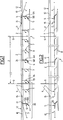
- the supply device 1 comprises a flexible conductor 2, connected at one end to a tension cable 3 and at its other end to another tension cable 4, pivoting suspension means hereinafter called consoles (two end consoles 5, a central console 6 and a plurality of intermediate consoles 7) and a drive cable 8 of the consoles 5, 6, 7.
- the flexible conductor 2 is connected to the cable 3 via a connection device 13 provided with an insulator, and connected to the tension cable 4 via a connection device 14 also provided with an insulator.
- Each console 5, 6, 7 comprises a support arm 5A, 6A, 7A and a drive arm 5B, 6B, 7B, these two arms being integral with one another.
- the flexible conductor 2 is supported above the railway 12 and between the two end-carrying arms 5A by all the carrying arms 7A from point to point. Therefore, the variation of the deflection of the flexible conductor 2 is almost zero, which makes it possible to lower the device as much as possible and thus obtain the smallest passage height under overhead rails 9 installed in the handling zone Z .
- Figure 1 shows this handling and storage area, delimited by the two overhead rails 9 at the ends. Between these two rails 9, this zone Z comprises a plurality of rails not shown, a pair of rails serving as a raceway for a handling device.
- Figure 1 also shows the end of two conductors 10 each connected to a tension cable 11 via a connection device 15 provided with an insulator.
- Each conductor 10 extends approximately between the end of zone Z and the catenary of the network, not shown.
- Each conductor 10 represents an electrical protection zone.
- FIG. 2 shows the position of the conductor 2 disengaged from the railway track 12 after rotation of all the consoles 5, 6, 7.
- the lateral clearance of the conductor 2 is of the order of approximately 3 meters.
- the rotation of all the consoles is carried out over 90 °, that is to say that the support arms 5A, 6A, 7A which were perpendicular to the track, are now parallel to the track and the drive arms 5B, 6B, 7B which were inclined to the left of the figure by approximately 45 °, are now inclined to the right by approximately 45 °.
- All the drive arms 5B, 6B, 7B are mechanically connected to the drive cable 8 and the lateral movement of this cable to the right of FIG. 1, causes all the drive arms to rotate and to all the support arms, therefore a lateral displacement of the conductor 2, but also a longitudinal displacement which will be explained later.
- Figure 3 shows more precisely the "left" end of the device according to the reference III of Figure 1
- Figure 4 shows a front view of Figure 3.
- the flexible conductor 2 a single tension cable 3
- an end console 5 an intermediate console 7
- a conductor 10 and an overhead rail 9 carried by a post 47 (visible in FIG. 4), this rail and its post constituting the "left" end of the handling and storage zone Z.
- the cable 3 ends at a post 16 reinforced by a reinforcing cable 17 biased, the end of this post 16 carrying a pulley 18, over which the tension cable passes 3.
- a counterweight 19, clearly visible in FIG. 4, is attached to the end of the cable 3, in order to tension this cable permanently.
- the conductor 2 is deviated from the track 12 vertically upwards, from the intermediate console 7 to the end console 5.
- the cable 3 is also deviated from the railway track 12 vertically upwards, but also laterally, as as shown in FIG. 3, between the end console 5 and the post 16.
- the end console 5 is carried by a post 20, the upper end of which comprises an axis of rotation for the support arm 5A and the drive arm 5B.
- This post is reinforced by two reinforcing cables 21, 22, tensioned at an angle.
- the other end console 5 not visible in Figures 3 and 4, is of course mounted in the same way.
- the intermediate console 7 is carried by a post 23, the upper end of which carries the axis of rotation of the support arm 7A and of the drive arm 7B.
- a post 23 the upper end of which carries the axis of rotation of the support arm 7A and of the drive arm 7B.
- all the other intermediate consoles are mounted in the same way.
- All the arms of each console can consist of triangular bars.
- the electrical insulation of the conductor 2 on the consoles can be obtained by an insulator with a horizontal axis or a group of insulators in a conventional manner.
- the drive cable 8 is mounted tensioned between two pulleys 24 only one of which is represented. This pulley 24 is carried by a post 25 reinforced by a reinforcing cable 26 biased.
- the drive cable has two strands, an upper strand 8A and a lower strand 8B, the upper strand 8A of this cable being connected to all the drive arms 5A, 6A, 7A of the consoles 5, 6, 7, by l 'through a device rotating around a vertical axis.
- the flexible conductor 2 is simply placed on the carrier arms 5A, 7A. However, it is fixed to the support arm 6A of the central console 6, at a point 24 (FIG. 1) which constitutes a fixed attachment point also called a "routing point”. Conductor 2 can also be attached at several points.
- the displacement of the flexible conductor 2 can be done by a motor means driving the drive cable 8 in translation, which causes the rotation of all the consoles or by another motor means driving the central console 6 in rotation, which causes l 'drive in translation of the cable 8, so the rotation of all the other consoles.
- a motor means driving the drive cable 8 in translation which causes the rotation of all the consoles
- another motor means driving the central console 6 in rotation which causes l 'drive in translation of the cable 8, so the rotation of all the other consoles.
- the installation can comprise two motor means acting simultaneously. These two motor means are conventional and are not shown.
- the flexible conductor 10 is connected to a tension cable 11 by means of a connection device 15 provided with an insulator.
- This conductor 10 constitutes a protective zone for the electric motors between the catenary represented by the retractable flexible conductor 2 and the network catenary which is located outside of FIGS. 3 and 4.
- These figures show only the "straight" end of the protection zone, that is to say the conductor 10 and its tension cable 11 leading to a post 27 reinforced by a reinforcement cable 28 stretched at an angle.
- the post 27 carries a pulley 29 over which the cable 11 passes.
- a counterweight 30 is fixed to the end of the cable 11 in order to tension this cable permanently.
- this conductor is connected to a tension cable itself connected to a counterweight.
- the conductor 10 is carried by suspension systems of which only two systems 31, 32 are shown. These systems are each mounted on a pole, respectively 33, 34.
- FIG. 5 shows in detail the suspension system 31 consisting of two inclined bars 35, each connected to a rigid block 36 fixed to the post 33.
- the lower bar 35 carries a horizontal bar 37 held by two reinforcing bars 38.
- a bracket 39 which carries an arm 40, itself carrying the conductor 10 by means of an electrical insulator not shown.
- FIG. 6 shows in detail the suspension system 32 consisting of two inclined bars 41, each connected to a rigid block 42 fixed to the post 34.
- the lower bar 41 carries a horizontal bar 43 held by a reinforcing bar 44.
- a bracket 45 which carries an arm 46, itself carrying the conductor 10 by means of an electrical insulator not shown.
- FIG. 3 shows the lateral clearance of the tension cable 3 from conductor 2, between the end console 5 and the post 16.
- FIG. 4 shows, from right to left, the conductor 2 which is substantially at constant height throughout the zone Z, then the vertical clearance towards the top of the conductor 2 substantially at the height of the intermediate console 7, up to the end console 5, and finally the vertical clearance towards the top of the tension cable 3 which extends the conductor 2.
- Figure 3 shows, from left to right, the conductor 10 which is at constant height with respect to the track, then its lateral clearance which is effected substantially from the suspension device 31.
- Figure 4 shows the vertical clearance of this conductor 10, substantially at the level of the suspension system 32.
- FIG. 5 shows that, towards the device 31, the conductor 10 is higher than the conductor 2 and slightly offset from the axis 47 of the track 12.
- the figure 6 shows that towards the device 32, the conductor 2 is above the conductor 10 and both are substantially in the axis of the track.
- the conductors 2 and the two conductors 10 are supplied electrically by known means.
- the supply line can be an on-site installation of 1500 Volts DC or 25 kV AC, and the retraction device can include another flexible two-wire retractable conductor.
- the pantograph 48 of a locomotive which comes from the left of FIG. 1 to enter zone Z, takes its electric current on, successively, the catenary of the network not shown, the conductor 10, then between the connection devices 13 and 15, conductor 2 over the entire length of zone Z.
- the locomotive stops at a specific location just beyond rail 9, so that each wagon is in front of a handling installation.
- the retraction operation is then carried out as follows.
- the motor means or means are actuated and the longitudinal displacement of the cable 8 causes the rotation of all the brackets 5, 6, 7, therefore the lateral retraction of the conductor 2, as illustrated in FIG. 2.
- the conductor 2 is fixed to the end of the central console and it undergoes a longitudinal displacement equal to the length of the support arm, this displacement being compensated for by the vertical displacement of the two counterweights 19 fixed to the end of the tension cables 3 and 4.
- the two counterweights 19 therefore move vertically and in a direction opposite to each other.
- the engine pantograph is lowered.
- the conductor 2 and the two conductors 10 are de-energized, while the overhead lines of the network remain energized.
- the handling devices are released and the engine means are controlled in the opposite direction, in order to bring the conductor 2 over the track.
- the conductor 2 and the two conductors 10 are again supplied with power.
- the locomotive's pantograph is raised and the locomotive can then drive the wagons outside of zone Z.
- This supply line according to the invention allows, like this clearly emerges from the description, a total retraction of the catenary, all along the handling and storage area.
Landscapes
- Engineering & Computer Science (AREA)
- Mechanical Engineering (AREA)
- Current-Collector Devices For Electrically Propelled Vehicles (AREA)
- Electric Propulsion And Braking For Vehicles (AREA)
- Storing, Repeated Paying-Out, And Re-Storing Of Elongated Articles (AREA)
- Forklifts And Lifting Vehicles (AREA)
Priority Applications (1)
| Application Number | Priority Date | Filing Date | Title |
|---|---|---|---|
| AT9191403231T ATE104612T1 (de) | 1990-12-03 | 1991-11-29 | Elektrische oberleitungsversorgungseinrichtung fuer schienenfahrzeuge mit einer biegsamen und horizontal schwenkbaren leitung sowie elektrisches leistungskabel mit einer solchen vorrichtung. |
Applications Claiming Priority (2)
| Application Number | Priority Date | Filing Date | Title |
|---|---|---|---|
| FR9015106A FR2669868B1 (fr) | 1990-12-03 | 1990-12-03 | Dispositif d'alimentation electrique aerienne de vehicules ferroviaires, a conducteur souple et escamotable horizontalement, et ligne d'alimentation electrique comportant au moins un tel dispositif. |
| FR9015106 | 1990-12-03 |
Publications (2)
| Publication Number | Publication Date |
|---|---|
| EP0489627A1 true EP0489627A1 (de) | 1992-06-10 |
| EP0489627B1 EP0489627B1 (de) | 1994-04-20 |
Family
ID=9402833
Family Applications (1)
| Application Number | Title | Priority Date | Filing Date |
|---|---|---|---|
| EP91403231A Expired - Lifetime EP0489627B1 (de) | 1990-12-03 | 1991-11-29 | Elektrische Oberleitungsversorgungseinrichtung für Schienenfahrzeuge mit einer biegsamen und horizontal schwenkbaren Leitung sowie elektrisches Leistungskabel mit einer solchen Vorrichtung |
Country Status (4)
| Country | Link |
|---|---|
| EP (1) | EP0489627B1 (de) |
| AT (1) | ATE104612T1 (de) |
| DE (1) | DE69101772T2 (de) |
| FR (1) | FR2669868B1 (de) |
Cited By (4)
| Publication number | Priority date | Publication date | Assignee | Title |
|---|---|---|---|---|
| WO1999005013A1 (de) * | 1997-07-26 | 1999-02-04 | Krupp Fördertechnik Gmbh | Verfahren und einrichtung zur handhabung von zugverbänden |
| WO2003013898A1 (de) * | 2001-08-10 | 2003-02-20 | Balfour Beatty Gmbh | Anordnung zur lageänderung von fahrleitungen |
| WO2007020297A1 (en) * | 2005-08-19 | 2007-02-22 | Tram Power Ltd | Overhead lines for rail vehicles |
| EP3153345A1 (de) * | 2015-10-08 | 2017-04-12 | Ing. Karl u. Albert Kruch GmbH & Co. KG | Anordnung zum halten der aus tragseil und fahrdraht bestehenden oberleitung elektrischer schienenfahrzeuge |
Families Citing this family (3)
| Publication number | Priority date | Publication date | Assignee | Title |
|---|---|---|---|---|
| DE102021206407A1 (de) * | 2021-06-22 | 2022-12-22 | Siemens Mobility GmbH | Oberleitungssystem mit windschiefem Parallelfeld |
| CN114633666B (zh) * | 2022-03-13 | 2025-08-29 | 兰州新伟车辆装备有限公司 | 伸出式支持装置、移动接触网及操作方法 |
| CN116767034B (zh) * | 2023-08-21 | 2023-12-26 | 四川智华电气有限公司 | 货运站场移动接触网供电体张紧方法 |
Citations (1)
| Publication number | Priority date | Publication date | Assignee | Title |
|---|---|---|---|---|
| DE1803762A1 (de) * | 1968-10-18 | 1970-06-11 | Licentia Gmbh | Anordnung von Fahrleitungen in Verladezonen |
-
1990
- 1990-12-03 FR FR9015106A patent/FR2669868B1/fr not_active Expired - Fee Related
-
1991
- 1991-11-29 EP EP91403231A patent/EP0489627B1/de not_active Expired - Lifetime
- 1991-11-29 DE DE69101772T patent/DE69101772T2/de not_active Expired - Fee Related
- 1991-11-29 AT AT9191403231T patent/ATE104612T1/de not_active IP Right Cessation
Patent Citations (1)
| Publication number | Priority date | Publication date | Assignee | Title |
|---|---|---|---|---|
| DE1803762A1 (de) * | 1968-10-18 | 1970-06-11 | Licentia Gmbh | Anordnung von Fahrleitungen in Verladezonen |
Cited By (4)
| Publication number | Priority date | Publication date | Assignee | Title |
|---|---|---|---|---|
| WO1999005013A1 (de) * | 1997-07-26 | 1999-02-04 | Krupp Fördertechnik Gmbh | Verfahren und einrichtung zur handhabung von zugverbänden |
| WO2003013898A1 (de) * | 2001-08-10 | 2003-02-20 | Balfour Beatty Gmbh | Anordnung zur lageänderung von fahrleitungen |
| WO2007020297A1 (en) * | 2005-08-19 | 2007-02-22 | Tram Power Ltd | Overhead lines for rail vehicles |
| EP3153345A1 (de) * | 2015-10-08 | 2017-04-12 | Ing. Karl u. Albert Kruch GmbH & Co. KG | Anordnung zum halten der aus tragseil und fahrdraht bestehenden oberleitung elektrischer schienenfahrzeuge |
Also Published As
| Publication number | Publication date |
|---|---|
| DE69101772D1 (de) | 1994-05-26 |
| ATE104612T1 (de) | 1994-05-15 |
| FR2669868A1 (fr) | 1992-06-05 |
| DE69101772T2 (de) | 1994-11-24 |
| FR2669868B1 (fr) | 1993-10-29 |
| EP0489627B1 (de) | 1994-04-20 |
Similar Documents
| Publication | Publication Date | Title |
|---|---|---|
| FR2735728A1 (fr) | Ensemble d'alimentation electrique et de guidage le long d'un rail au sol pour vehicule sur roues | |
| FR2773603A1 (fr) | Dispositif et procede d'installation de conduites a tres grandes profondeurs | |
| EP0489627B1 (de) | Elektrische Oberleitungsversorgungseinrichtung für Schienenfahrzeuge mit einer biegsamen und horizontal schwenkbaren Leitung sowie elektrisches Leistungskabel mit einer solchen Vorrichtung | |
| FR2653478A1 (fr) | Dispositif d'entrainement et de deplacement d'elements supports de baches constituant une couverture mobile. | |
| EP3456601B1 (de) | Fördersystem eines länglichen bauelements, förderfahrzeug, das mit einem solchen system ausgestattet ist | |
| EP0026147B1 (de) | Automatische Eindrahtungsvorrichtung eines elektrischen Fahrzeugs vom Typ des Oberleitungsbusses | |
| EP0663328A1 (de) | Transportanlage mit zwei Luftreilkabeln | |
| EP0505240B1 (de) | Vorrichtung zum Ver- und Ersetzen von Eisenbahnelementen und Verfahren zur Verwendung dieser Vorrichtung | |
| WO1989006578A1 (fr) | Dispositif pour projeter un revetement sur la surface interieure d'un recipient de transvasement de metal liquide et procede s'y rapportant | |
| EP0927658B1 (de) | Abwickel- und Verlegeinrichtung für Leitungen, zum beispiel Stromoberleitungen | |
| EP0349390B1 (de) | Einrichtung vom Typ U-Bahn für den gemeinschaftlichen Transport von Passagieren mit automatischen Antrieb durch unabhängige Zugwagen, insb. unter Verwendung des Antriebs durch einen Linearmotor | |
| EP0474547B1 (de) | Oberirdische elektrische Versorgungsvorrichtung für Eisenbahnfahrzeuge mit einer steifen ausklappbaren Leiter und Fahrleitung oder Fahrleitungskomplex mit mindestens einer solchen Vorrichtung | |
| WO2014001393A1 (fr) | Dispositif pour la manutention de conteneurs sous caténaires ferroviaires | |
| EP0467001B1 (de) | Zug zum Verlegen neuer Gleise und Verfahren zum Verlegen derselben mit einem solchen Zug | |
| FR3059949A1 (fr) | Connecteur electrique de catenaire, et ensemble d'une catenaire de voie et d'une catenaire escamotable comprenant un tel connecteur | |
| EP0773153A1 (de) | Bewegliche Plattform für die Überwachung von Höhenunterschieden | |
| FR2616718A1 (fr) | Dispositif pour tendre un systeme catenaire dans un tunnel | |
| CH650045A5 (fr) | Machine de chantier ferroviaire pour la saisie et le portage de troncons et/ou d'appareils de voie montes. | |
| FR2478571A1 (fr) | Dispositif de levage de la plate-forme d'une installation de mise a terre ou a l'eau des navires | |
| EP1849720A1 (de) | Mobile vertikale Speichervorrichtung | |
| FR2504100A1 (fr) | Convoyeur a portique et installation de stockage comportant un tel convoyeur | |
| CH632547A5 (fr) | Bourreuse de voies ferrees. | |
| FR2831567A1 (fr) | Dispositif pour le relevage temporaire d'un panneau de signalisation sur portique ou potence | |
| EP0630840B1 (de) | Transporteinrichtung mit Linearmotorantrieb mit Träger, die um eine Bahn zirkulieren | |
| EP0831040A1 (de) | Einrichtung zum Speichern von Gegenständen auf einer Förderschleife |
Legal Events
| Date | Code | Title | Description |
|---|---|---|---|
| PUAI | Public reference made under article 153(3) epc to a published international application that has entered the european phase |
Free format text: ORIGINAL CODE: 0009012 |
|
| AK | Designated contracting states |
Kind code of ref document: A1 Designated state(s): AT BE CH DE DK ES GB GR IT LI LU NL |
|
| 17P | Request for examination filed |
Effective date: 19920710 |
|
| 17Q | First examination report despatched |
Effective date: 19930225 |
|
| GRAA | (expected) grant |
Free format text: ORIGINAL CODE: 0009210 |
|
| AK | Designated contracting states |
Kind code of ref document: B1 Designated state(s): AT BE CH DE DK ES GB GR IT LI LU NL |
|
| PG25 | Lapsed in a contracting state [announced via postgrant information from national office to epo] |
Ref country code: GR Free format text: LAPSE BECAUSE OF FAILURE TO SUBMIT A TRANSLATION OF THE DESCRIPTION OR TO PAY THE FEE WITHIN THE PRESCRIBED TIME-LIMIT Effective date: 19940420 Ref country code: ES Free format text: THE PATENT HAS BEEN ANNULLED BY A DECISION OF A NATIONAL AUTHORITY Effective date: 19940420 Ref country code: DK Effective date: 19940420 Ref country code: AT Effective date: 19940420 |
|
| REF | Corresponds to: |
Ref document number: 104612 Country of ref document: AT Date of ref document: 19940515 Kind code of ref document: T |
|
| REF | Corresponds to: |
Ref document number: 69101772 Country of ref document: DE Date of ref document: 19940526 |
|
| ITF | It: translation for a ep patent filed | ||
| GBT | Gb: translation of ep patent filed (gb section 77(6)(a)/1977) |
Effective date: 19940711 |
|
| PG25 | Lapsed in a contracting state [announced via postgrant information from national office to epo] |
Ref country code: CH Effective date: 19941130 Ref country code: BE Effective date: 19941130 Ref country code: LU Free format text: LAPSE BECAUSE OF NON-PAYMENT OF DUE FEES Effective date: 19941130 Ref country code: LI Effective date: 19941130 |
|
| PLBE | No opposition filed within time limit |
Free format text: ORIGINAL CODE: 0009261 |
|
| STAA | Information on the status of an ep patent application or granted ep patent |
Free format text: STATUS: NO OPPOSITION FILED WITHIN TIME LIMIT |
|
| 26N | No opposition filed | ||
| BERE | Be: lapsed |
Owner name: SOC. NATIONALE DES CHEMINS DE FER FRANCAIS Effective date: 19941130 |
|
| REG | Reference to a national code |
Ref country code: CH Ref legal event code: PL |
|
| PGFP | Annual fee paid to national office [announced via postgrant information from national office to epo] |
Ref country code: GB Payment date: 20001121 Year of fee payment: 10 |
|
| PG25 | Lapsed in a contracting state [announced via postgrant information from national office to epo] |
Ref country code: GB Free format text: LAPSE BECAUSE OF NON-PAYMENT OF DUE FEES Effective date: 20011129 |
|
| REG | Reference to a national code |
Ref country code: GB Ref legal event code: IF02 |
|
| GBPC | Gb: european patent ceased through non-payment of renewal fee |
Effective date: 20011129 |
|
| PG25 | Lapsed in a contracting state [announced via postgrant information from national office to epo] |
Ref country code: IT Free format text: LAPSE BECAUSE OF NON-PAYMENT OF DUE FEES;WARNING: LAPSES OF ITALIAN PATENTS WITH EFFECTIVE DATE BEFORE 2007 MAY HAVE OCCURRED AT ANY TIME BEFORE 2007. THE CORRECT EFFECTIVE DATE MAY BE DIFFERENT FROM THE ONE RECORDED. Effective date: 20051129 |
|
| NLS | Nl: assignments of ep-patents |
Owner name: LA SOCIETE TECHNIQUE POUR L'ENERGIE ATOMIQUE-TECHN Effective date: 20070712 |
|
| PGFP | Annual fee paid to national office [announced via postgrant information from national office to epo] |
Ref country code: DE Payment date: 20081113 Year of fee payment: 18 Ref country code: NL Payment date: 20081021 Year of fee payment: 18 |
|
| REG | Reference to a national code |
Ref country code: NL Ref legal event code: V1 Effective date: 20100601 |
|
| PG25 | Lapsed in a contracting state [announced via postgrant information from national office to epo] |
Ref country code: NL Free format text: LAPSE BECAUSE OF NON-PAYMENT OF DUE FEES Effective date: 20100601 |
|
| PG25 | Lapsed in a contracting state [announced via postgrant information from national office to epo] |
Ref country code: DE Free format text: LAPSE BECAUSE OF NON-PAYMENT OF DUE FEES Effective date: 20100601 |