EP0489676A1 - Bodenrinnenrost und Verbindungsvorrichtung dafür - Google Patents
Bodenrinnenrost und Verbindungsvorrichtung dafür Download PDFInfo
- Publication number
- EP0489676A1 EP0489676A1 EP91470035A EP91470035A EP0489676A1 EP 0489676 A1 EP0489676 A1 EP 0489676A1 EP 91470035 A EP91470035 A EP 91470035A EP 91470035 A EP91470035 A EP 91470035A EP 0489676 A1 EP0489676 A1 EP 0489676A1
- Authority
- EP
- European Patent Office
- Prior art keywords
- bar
- finger
- connecting means
- means according
- elastically deformable
- Prior art date
- Legal status (The legal status is an assumption and is not a legal conclusion. Google has not performed a legal analysis and makes no representation as to the accuracy of the status listed.)
- Granted
Links
Images

Classifications
-
- E—FIXED CONSTRUCTIONS
- E03—WATER SUPPLY; SEWERAGE
- E03F—SEWERS; CESSPOOLS
- E03F5/00—Sewerage structures
- E03F5/04—Gullies inlets, road sinks, floor drains with or without odour seals or sediment traps
- E03F5/06—Gully gratings
-
- E—FIXED CONSTRUCTIONS
- E03—WATER SUPPLY; SEWERAGE
- E03F—SEWERS; CESSPOOLS
- E03F5/00—Sewerage structures
- E03F5/04—Gullies inlets, road sinks, floor drains with or without odour seals or sediment traps
- E03F5/06—Gully gratings
- E03F2005/065—Gully gratings with elastic locking elements
Definitions
- the present invention relates to connecting means for the junction of two adjacent road parts intended to be placed on a support structure, such as for example gates of chained gutters or multi-channel pit traps.
- gutters In environments such as airports, overflow pools, the floors of buildings in which water is used for various operations, or even city streets or highways, it is common to use gutters for the evacuation of water. These gutters generally have a poured concrete edge on which two metal beams are fixed intended to support the road parts.
- the road parts for example grids, are simply placed next to each other on the side rails.
- connection means lies in the need to use added elements.
- road parts are generally installed in an environment where dust and dirt accumulate, the chaining screws seize up and their operation becomes very difficult when it is necessary to dismantle the parts to intervene on the network.
- Another solution consists in using road parts whose end faces in contact with neighboring parts are provided with complementary hooking members coming into mutual engagement.
- the fastening members are rigid, and the drawback of this type of connection means lies in the fact that, to assemble or disassemble a road part provided with such means, it is necessary to hold two by hand. parts raised. However, an average piece often weighs around 40 kg.
- the present invention aims to provide connecting means for the junction of two road parts which allow to overcome these drawbacks.
- the present invention relates, for this purpose, connecting means for the junction of two road parts juxtaposed in a longitudinal direction and intended to be placed on a support structure, for example a drainage channel or a trap door frame multi-channel, these means being characterized in that they comprise an elastically deformable bar integral with one of the parts to be joined and housed in a window thereof, and a finger integral with the other part and projecting in the direction longitudinal thereon, which finger has a bead adapted to snap by cooperation with the elastic bar.
- the present invention also relates to a road component having connecting means as defined above, with at one of its ends at least one elastically deformable bar and, at the opposite end, at least one projecting finger latching.
- the part has a window at each end, the two elastic bars being oriented head to tail, one of the two fingers having a U shape and the other an inverted U shape.
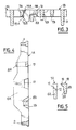
- FIG. 1 the adjacent end portions of two gutter grids 1A, 1B, identical and of generally rectangular shape, each of which is constituted by a cast iron cast part. These grids are intended to be placed on two support rails, not shown, located on either side of a gutter.
- Each grid comprises on each side a lateral beam 2, and the two beams are connected at regular intervals, over the entire current part of the grid, by transverse bars 3 which also connects a median beam 4.
- the elements 2 to 4 thus delimit a number of half-windows 5 of generally rectangular shape.
- the right end part (considering FIG. 1) of the left grid 1A comprises an end transverse bar 6A connecting the two longitudinal members 2, and between this bar and the nearest bar 3, an elastic bar 7A connected to the only upper spar 2 (considering Figure 1) and extending transversely to a small distance from the other spar 2.
- the bar 6A carries, roughly a quarter of its length from the upper spar 2, a finger 8A in the shape of a U (FIG. 2) projecting in the longitudinal direction.
- the outer or right arm of this finger carries on its side furthest from the bar 6A a bead forming a double cam and comprising, considering FIG. 2, an upper ramp 9A inclined downwards and outwards and a lower ramp 10A inclined downwards and inwards, that is to say towards the grid 1A.
- the bar 6A has in its upper face a notch 11 whose outer face 12 is inclined downward and outward. In addition, at about three-quarters of its length, the bar 6A has another notch 13 formed in its upper face.
- the bar 7A has on its outer vertical face, that is to say facing the bar 6A, a double cam similar to that of the finger 8A, that is to say comprising an upper ramp 14A inclined downward and outward and a lower ramp 15A inclined downward and inward.
- This double cam the inclinations of which correspond to those of the double cam 9A, 10A, is located, in plan view (FIG. 1), facing the notch 13.
- the bar 7A can deform elastically in the plane of FIG. 1, inside the window 16A of generally rectangular shape delimited by the two longitudinal members 2, the bar 6A and the bar 7A.
- the amplitude of this deformation is limited by stops 17, 18 projecting respectively from the elements 6A and 7A.
- the elements bordering the window 16A protect the bar 7A from all sides against possible shocks.
- the left end part (considering FIG. 1) of the right grid 1B comprises an end transverse bar 6B connecting the two longitudinal members 2, and, between this bar and the nearest bar 3, a bar 7B elastically deformable connected to the only lower spar 2 (considering the Figure 1) and extending transversely to a small distance from the other spar 2.
- the bar 6B carries, roughly a quarter of its length from the lower spar 2, a finger 8B in the shape of an inverted U (FIG. 3) projecting in the longitudinal direction.
- the outer or left branch of this finger carries on its side furthest from the bar 6B a bead forming a double cam and comprising, considering FIG. 3, an upper ramp 9B inclined downwards and outwards and a lower ramp 10B inclined downwards and inwards, that is to say towards the grid 1B.
- the bar 6B has in its upper plane a projection 19 oriented towards the outside and, below the latter, an inclined overhanging surface 20.
- the bar 7B has on its outer vertical face, that is to say facing the bar 6B, a double cam similar to that of the finger 8B, that is to say comprising an upper ramp 14B inclined downwards and outwards and a lower ramp 15B inclined downwards and inwards.
- the bar 7B can deform elastically in the plane of Figure 1, inside a rectangular window 16B, and the bar 6B and the bar 3 adjacent to the bar 7B have projections limiting this displacement.
- the grid 1A is in place on its support beams.
- the grid 1B is placed in its extension, so that the bar 6B is at plumb with the hollow of the finger 8A and the trough of the finger 8B is plumb with the bar 6A.
- the lower ramp 10B of the finger 8B thus comes into contact with the upper ramp 14A of the bar 7A, and simultaneously the lower ramp 15B of the bar 7B comes into contact with the upper ramp 9A of the finger 8A.
- the ramps 10B and 9A repel elastically, by cam effect, the free ends of the bars 7A and 7B, then the ends of the two fingers snap in, with contact d on the one hand of the ramps 9B and 15A ( Figure 3), on the other hand of the ramps 10A and 14B ( Figure 2).
- the two grids are then hooked to each other.
- attachment ramps 10A, 14B ( Figure 2) and 9B, 15A ( Figure 3) can be replaced by horizontal surfaces.
Landscapes
- Health & Medical Sciences (AREA)
- Life Sciences & Earth Sciences (AREA)
- Engineering & Computer Science (AREA)
- Hydrology & Water Resources (AREA)
- Public Health (AREA)
- Water Supply & Treatment (AREA)
- Sewage (AREA)
- Road Paving Structures (AREA)
- Paper (AREA)
- Soil Working Implements (AREA)
- Ultra Sonic Daignosis Equipment (AREA)
- Joining Of Corner Units Of Frames Or Wings (AREA)
- Input Circuits Of Receivers And Coupling Of Receivers And Audio Equipment (AREA)
- Electrochromic Elements, Electrophoresis, Or Variable Reflection Or Absorption Elements (AREA)
- Feeding And Controlling Fuel (AREA)
- Electrodes For Cathode-Ray Tubes (AREA)
- Mutual Connection Of Rods And Tubes (AREA)
- Measuring Pulse, Heart Rate, Blood Pressure Or Blood Flow (AREA)
- Road Signs Or Road Markings (AREA)
- Details Of Connecting Devices For Male And Female Coupling (AREA)
- Piles And Underground Anchors (AREA)
- Incineration Of Waste (AREA)
- Joining Of Building Structures In Genera (AREA)
- Connection Of Plates (AREA)
- Snaps, Bayonet Connections, Set Pins, And Snap Rings (AREA)
- Catching Or Destruction (AREA)
- Feeding And Watering For Cattle Raising And Animal Husbandry (AREA)
- Steps, Ramps, And Handrails (AREA)
Applications Claiming Priority (2)
| Application Number | Priority Date | Filing Date | Title |
|---|---|---|---|
| FR9014818A FR2669655B1 (fr) | 1990-11-27 | 1990-11-27 | Moyens de liaison pour pieces de voirie, et piece de voirie correspondante. |
| FR9014818 | 1990-11-27 |
Publications (2)
| Publication Number | Publication Date |
|---|---|
| EP0489676A1 true EP0489676A1 (de) | 1992-06-10 |
| EP0489676B1 EP0489676B1 (de) | 1994-06-08 |
Family
ID=9402642
Family Applications (1)
| Application Number | Title | Priority Date | Filing Date |
|---|---|---|---|
| EP91470035A Expired - Lifetime EP0489676B1 (de) | 1990-11-27 | 1991-11-15 | Bodenrinnenrost und Verbindungsvorrichtung dafür |
Country Status (9)
| Country | Link |
|---|---|
| EP (1) | EP0489676B1 (de) |
| AT (1) | ATE106976T1 (de) |
| DE (1) | DE69102404T2 (de) |
| DK (1) | DK0489676T3 (de) |
| ES (1) | ES2048127T3 (de) |
| FR (1) | FR2669655B1 (de) |
| IE (1) | IE65474B1 (de) |
| NO (1) | NO303739B1 (de) |
| PT (1) | PT8400U (de) |
Cited By (4)
| Publication number | Priority date | Publication date | Assignee | Title |
|---|---|---|---|---|
| FR2718177A1 (fr) * | 1994-03-30 | 1995-10-06 | Norinco | Dispositif de verrouillage d'une grille sur un châssis ou analogue. |
| EP0694654A1 (de) * | 1994-07-29 | 1996-01-31 | Pont-A-Mousson S.A. | Bodenrinnenrost |
| EP1052337A1 (de) * | 1999-05-11 | 2000-11-15 | Norinco | Strasseneinlauf mit angelenktem und verriegeltem Deckel und Rost |
| US7303669B2 (en) * | 2002-08-02 | 2007-12-04 | Norinco | Grate for closing a drain and similar |
Families Citing this family (1)
| Publication number | Priority date | Publication date | Assignee | Title |
|---|---|---|---|---|
| RU2336392C2 (ru) | 2003-03-25 | 2008-10-20 | Ако Зеверин Альманн Гмбх Унд Ко. Кг | Закрывающее устройство |
Citations (6)
| Publication number | Priority date | Publication date | Assignee | Title |
|---|---|---|---|---|
| FR2384904A1 (fr) * | 1977-03-23 | 1978-10-20 | Selflevel Covers Ag | Grille pour equipement de chaussee |
| EP0085306A2 (de) * | 1982-01-29 | 1983-08-10 | Brickhouse Dudley Manufacturing Limited | Einheiten bestehend aus Abdeckungen und Zargrahmen |
| DE8716448U1 (de) * | 1987-12-12 | 1988-02-04 | Riegelhof & Gärtner Walter Hinrichs Erben Metallwarenfabrik, 6070 Langen | Anschlußdeckel für Bodenabläufe od. dgl. |
| EP0280872A1 (de) * | 1987-02-02 | 1988-09-07 | Von Roll Ag | Einrichtung zum Sichern einer eine Öffnung abschliessenden Abdeckung |
| DE9006179U1 (de) * | 1989-06-01 | 1990-08-30 | Pont-à-Mousson S.A., Nancy | Verbindungseinrichtung für die Verbindung von zwei Teilen von Verkehrswegen |
| EP0337110B1 (de) * | 1988-04-15 | 1992-08-05 | Von Roll Ag | Bodenwasserablauf |
-
1990
- 1990-11-27 FR FR9014818A patent/FR2669655B1/fr not_active Expired - Fee Related
-
1991
- 1991-11-15 DK DK91470035.6T patent/DK0489676T3/da active
- 1991-11-15 AT AT91470035T patent/ATE106976T1/de not_active IP Right Cessation
- 1991-11-15 DE DE69102404T patent/DE69102404T2/de not_active Expired - Lifetime
- 1991-11-15 ES ES91470035T patent/ES2048127T3/es not_active Expired - Lifetime
- 1991-11-15 EP EP91470035A patent/EP0489676B1/de not_active Expired - Lifetime
- 1991-11-25 PT PT8400U patent/PT8400U/pt not_active IP Right Cessation
- 1991-11-25 NO NO914605A patent/NO303739B1/no not_active IP Right Cessation
- 1991-11-26 IE IE411091A patent/IE65474B1/en not_active IP Right Cessation
Patent Citations (6)
| Publication number | Priority date | Publication date | Assignee | Title |
|---|---|---|---|---|
| FR2384904A1 (fr) * | 1977-03-23 | 1978-10-20 | Selflevel Covers Ag | Grille pour equipement de chaussee |
| EP0085306A2 (de) * | 1982-01-29 | 1983-08-10 | Brickhouse Dudley Manufacturing Limited | Einheiten bestehend aus Abdeckungen und Zargrahmen |
| EP0280872A1 (de) * | 1987-02-02 | 1988-09-07 | Von Roll Ag | Einrichtung zum Sichern einer eine Öffnung abschliessenden Abdeckung |
| DE8716448U1 (de) * | 1987-12-12 | 1988-02-04 | Riegelhof & Gärtner Walter Hinrichs Erben Metallwarenfabrik, 6070 Langen | Anschlußdeckel für Bodenabläufe od. dgl. |
| EP0337110B1 (de) * | 1988-04-15 | 1992-08-05 | Von Roll Ag | Bodenwasserablauf |
| DE9006179U1 (de) * | 1989-06-01 | 1990-08-30 | Pont-à-Mousson S.A., Nancy | Verbindungseinrichtung für die Verbindung von zwei Teilen von Verkehrswegen |
Cited By (7)
| Publication number | Priority date | Publication date | Assignee | Title |
|---|---|---|---|---|
| FR2718177A1 (fr) * | 1994-03-30 | 1995-10-06 | Norinco | Dispositif de verrouillage d'une grille sur un châssis ou analogue. |
| EP0694654A1 (de) * | 1994-07-29 | 1996-01-31 | Pont-A-Mousson S.A. | Bodenrinnenrost |
| FR2723118A1 (fr) * | 1994-07-29 | 1996-02-02 | Pont A Mousson | Dispositif de voirie |
| EP1052337A1 (de) * | 1999-05-11 | 2000-11-15 | Norinco | Strasseneinlauf mit angelenktem und verriegeltem Deckel und Rost |
| FR2793502A1 (fr) * | 1999-05-11 | 2000-11-17 | Norinco | Bouche d'egout a couvercle et grille articules et verrouilles |
| CZ298041B6 (cs) * | 1999-05-11 | 2007-05-30 | Norinco | Výrobek pro osazení do otvoru v komunikaci |
| US7303669B2 (en) * | 2002-08-02 | 2007-12-04 | Norinco | Grate for closing a drain and similar |
Also Published As
| Publication number | Publication date |
|---|---|
| NO914605L (no) | 1992-05-29 |
| FR2669655B1 (fr) | 1993-03-05 |
| DE69102404D1 (de) | 1994-07-14 |
| IE914110A1 (en) | 1992-06-03 |
| ATE106976T1 (de) | 1994-06-15 |
| PT8400U (pt) | 1994-10-31 |
| NO914605D0 (no) | 1991-11-25 |
| NO303739B1 (no) | 1998-08-24 |
| ES2048127T1 (es) | 1994-03-16 |
| PT8400T (pt) | 1992-05-29 |
| ES2048127T3 (es) | 1994-08-16 |
| IE65474B1 (en) | 1995-11-01 |
| DE69102404T2 (de) | 1994-10-20 |
| DK0489676T3 (da) | 1994-10-24 |
| EP0489676B1 (de) | 1994-06-08 |
| FR2669655A1 (fr) | 1992-05-29 |
Similar Documents
| Publication | Publication Date | Title |
|---|---|---|
| FR2484505A1 (fr) | Boiserie et support de panneaux pour boiserie | |
| FR2638772A1 (fr) | Dispositif pour retenir la neige sur une toiture en tole et toiture equipee d'un tel dispositif | |
| EP0489676B1 (de) | Bodenrinnenrost und Verbindungsvorrichtung dafür | |
| EP0401146B1 (de) | Verbindungsmittel zur Zusammenfügung zweier Teile einer Verkehrsfläche | |
| EP0347388A1 (de) | Modulare, verlaufsveränderliche Absperrung zum Bilden einer Schutzumfriedung | |
| FR2852065A1 (fr) | Pince de fixation | |
| CH649594A5 (fr) | Chassis de voirie a couvercle basculant amovible. | |
| EP0694654B1 (de) | Verkehrswege-Einrichtung | |
| FR2584761A3 (fr) | Passerelle metallique, notamment pour echafaudage | |
| WO1991019063A1 (fr) | Support de faux-planchers pour salles techniques, notamment salles d'informatique | |
| CH648622A5 (fr) | Grille pour ouvrage de chaussee, notamment pour bouche d'egout. | |
| EP1030949B1 (de) | Rechtwinklige oder quadratische strassennetzvorrichtung mit einem traggerüst und einer abdeckung | |
| FR2710091A1 (fr) | Dispositif de mise en place et de positionnement d'armature dans des coffrages pour béton armé. | |
| WO1991000391A1 (fr) | Dispositif de fixation elastique d'un rail de chemin de fer sur son support | |
| EP0301658B1 (de) | Kupplungselement für Unterdecken | |
| EP0668410B1 (de) | Modulares Rost zum Beispiel für Rinnenabdeckung | |
| EP3581735A1 (de) | Geländer | |
| EP3906971B1 (de) | Schutzvorrichtung für seil und schutzsystem | |
| EP0068915A1 (de) | Schwenkbares Tor, auch grosser Breite, auf unebenem Gelände, ohne Notwendigkeit eines Stützpfostens | |
| FR2682698A3 (en) | Adaptive modular barrier for defining a protected perimeter | |
| FR2749871A1 (fr) | Element de plancher pour echafaudage | |
| EP1452649A1 (de) | Wasserdichtende Schachtabdeckung | |
| FR2516115A1 (fr) | Procedes de pose d'ossatures pour puits et bouches d'acces et installations et ossatures pour la mise en oeuvre desdits procedes | |
| FR3042804A1 (fr) | Ensemble pour la construction d'un support lateral a un escalier provisoire pour chantier et escalier provisoire comportant un tel ensemble | |
| EP0688914A1 (de) | Befestigungsvorrichtung für Gebäudewände, insbesondere industriell vorgefertigte Module vom Bungalow-Typ |
Legal Events
| Date | Code | Title | Description |
|---|---|---|---|
| PUAI | Public reference made under article 153(3) epc to a published international application that has entered the european phase |
Free format text: ORIGINAL CODE: 0009012 |
|
| AK | Designated contracting states |
Kind code of ref document: A1 Designated state(s): AT BE CH DE DK ES FR GB GR IT LI LU NL SE |
|
| 17P | Request for examination filed |
Effective date: 19921120 |
|
| 17Q | First examination report despatched |
Effective date: 19931118 |
|
| GRAA | (expected) grant |
Free format text: ORIGINAL CODE: 0009210 |
|
| AK | Designated contracting states |
Kind code of ref document: B1 Designated state(s): AT BE CH DE DK ES FR GB GR IT LI LU NL SE |
|
| REF | Corresponds to: |
Ref document number: 106976 Country of ref document: AT Date of ref document: 19940615 Kind code of ref document: T |
|
| ITF | It: translation for a ep patent filed | ||
| REF | Corresponds to: |
Ref document number: 69102404 Country of ref document: DE Date of ref document: 19940714 |
|
| GBT | Gb: translation of ep patent filed (gb section 77(6)(a)/1977) |
Effective date: 19940624 |
|
| REG | Reference to a national code |
Ref country code: ES Ref legal event code: FG2A Ref document number: 2048127 Country of ref document: ES Kind code of ref document: T3 |
|
| REG | Reference to a national code |
Ref country code: GR Ref legal event code: FG4A Free format text: 3012788 |
|
| REG | Reference to a national code |
Ref country code: DK Ref legal event code: T3 |
|
| EAL | Se: european patent in force in sweden |
Ref document number: 91470035.6 |
|
| PLBE | No opposition filed within time limit |
Free format text: ORIGINAL CODE: 0009261 |
|
| STAA | Information on the status of an ep patent application or granted ep patent |
Free format text: STATUS: NO OPPOSITION FILED WITHIN TIME LIMIT |
|
| 26N | No opposition filed | ||
| REG | Reference to a national code |
Ref country code: GB Ref legal event code: IF02 |
|
| PGFP | Annual fee paid to national office [announced via postgrant information from national office to epo] |
Ref country code: LU Payment date: 20081119 Year of fee payment: 18 Ref country code: NL Payment date: 20081103 Year of fee payment: 18 Ref country code: DK Payment date: 20081114 Year of fee payment: 18 Ref country code: CH Payment date: 20081117 Year of fee payment: 18 |
|
| PGFP | Annual fee paid to national office [announced via postgrant information from national office to epo] |
Ref country code: AT Payment date: 20081112 Year of fee payment: 18 |
|
| PGFP | Annual fee paid to national office [announced via postgrant information from national office to epo] |
Ref country code: SE Payment date: 20081107 Year of fee payment: 18 Ref country code: BE Payment date: 20081110 Year of fee payment: 18 |
|
| PGFP | Annual fee paid to national office [announced via postgrant information from national office to epo] |
Ref country code: FR Payment date: 20081112 Year of fee payment: 18 |
|
| PGFP | Annual fee paid to national office [announced via postgrant information from national office to epo] |
Ref country code: GR Payment date: 20081016 Year of fee payment: 18 |
|
| BERE | Be: lapsed |
Owner name: S.A. *PONT-A-MOUSSON Effective date: 20091130 |
|
| REG | Reference to a national code |
Ref country code: NL Ref legal event code: V1 Effective date: 20100601 |
|
| EUG | Se: european patent has lapsed | ||
| REG | Reference to a national code |
Ref country code: CH Ref legal event code: PL |
|
| REG | Reference to a national code |
Ref country code: DK Ref legal event code: EBP |
|
| REG | Reference to a national code |
Ref country code: FR Ref legal event code: ST Effective date: 20100730 |
|
| PG25 | Lapsed in a contracting state [announced via postgrant information from national office to epo] |
Ref country code: AT Free format text: LAPSE BECAUSE OF NON-PAYMENT OF DUE FEES Effective date: 20091115 |
|
| PG25 | Lapsed in a contracting state [announced via postgrant information from national office to epo] |
Ref country code: GR Free format text: LAPSE BECAUSE OF NON-PAYMENT OF DUE FEES Effective date: 20100602 Ref country code: NL Free format text: LAPSE BECAUSE OF NON-PAYMENT OF DUE FEES Effective date: 20100601 Ref country code: LI Free format text: LAPSE BECAUSE OF NON-PAYMENT OF DUE FEES Effective date: 20091130 Ref country code: FR Free format text: LAPSE BECAUSE OF NON-PAYMENT OF DUE FEES Effective date: 20091130 Ref country code: CH Free format text: LAPSE BECAUSE OF NON-PAYMENT OF DUE FEES Effective date: 20091130 Ref country code: BE Free format text: LAPSE BECAUSE OF NON-PAYMENT OF DUE FEES Effective date: 20091130 |
|
| PG25 | Lapsed in a contracting state [announced via postgrant information from national office to epo] |
Ref country code: DK Free format text: LAPSE BECAUSE OF NON-PAYMENT OF DUE FEES Effective date: 20091130 |
|
| PGFP | Annual fee paid to national office [announced via postgrant information from national office to epo] |
Ref country code: DE Payment date: 20101110 Year of fee payment: 20 |
|
| PGFP | Annual fee paid to national office [announced via postgrant information from national office to epo] |
Ref country code: GB Payment date: 20101110 Year of fee payment: 20 Ref country code: IT Payment date: 20101120 Year of fee payment: 20 |
|
| PG25 | Lapsed in a contracting state [announced via postgrant information from national office to epo] |
Ref country code: LU Free format text: LAPSE BECAUSE OF NON-PAYMENT OF DUE FEES Effective date: 20091115 |
|
| PG25 | Lapsed in a contracting state [announced via postgrant information from national office to epo] |
Ref country code: SE Free format text: LAPSE BECAUSE OF NON-PAYMENT OF DUE FEES Effective date: 20091116 |
|
| PGFP | Annual fee paid to national office [announced via postgrant information from national office to epo] |
Ref country code: ES Payment date: 20101217 Year of fee payment: 20 |
|
| REG | Reference to a national code |
Ref country code: DE Ref legal event code: R071 Ref document number: 69102404 Country of ref document: DE |
|
| REG | Reference to a national code |
Ref country code: DE Ref legal event code: R071 Ref document number: 69102404 Country of ref document: DE |
|
| REG | Reference to a national code |
Ref country code: GB Ref legal event code: PE20 Expiry date: 20111114 |
|
| PG25 | Lapsed in a contracting state [announced via postgrant information from national office to epo] |
Ref country code: GB Free format text: LAPSE BECAUSE OF EXPIRATION OF PROTECTION Effective date: 20111114 |
|
| REG | Reference to a national code |
Ref country code: ES Ref legal event code: FD2A Effective date: 20120511 |
|
| PG25 | Lapsed in a contracting state [announced via postgrant information from national office to epo] |
Ref country code: ES Free format text: LAPSE BECAUSE OF EXPIRATION OF PROTECTION Effective date: 20111116 |
|
| PG25 | Lapsed in a contracting state [announced via postgrant information from national office to epo] |
Ref country code: DE Free format text: LAPSE BECAUSE OF EXPIRATION OF PROTECTION Effective date: 20111116 |