EP0489859B1 - Rotor a pertes par ventilation reduites - Google Patents
Rotor a pertes par ventilation reduites Download PDFInfo
- Publication number
- EP0489859B1 EP0489859B1 EP90914331A EP90914331A EP0489859B1 EP 0489859 B1 EP0489859 B1 EP 0489859B1 EP 90914331 A EP90914331 A EP 90914331A EP 90914331 A EP90914331 A EP 90914331A EP 0489859 B1 EP0489859 B1 EP 0489859B1
- Authority
- EP
- European Patent Office
- Prior art keywords
- rotor
- axially
- extending
- recesses
- salient poles
- Prior art date
- Legal status (The legal status is an assumption and is not a legal conclusion. Google has not performed a legal analysis and makes no representation as to the accuracy of the status listed.)
- Expired - Lifetime
Links
- 239000000696 magnetic material Substances 0.000 claims abstract description 19
- 238000010276 construction Methods 0.000 claims description 11
- 238000004804 winding Methods 0.000 claims description 10
- 239000007787 solid Substances 0.000 claims description 4
- 241000191291 Abies alba Species 0.000 claims description 3
- 238000000034 method Methods 0.000 claims description 3
- 229920003217 poly(methylsilsesquioxane) Polymers 0.000 claims description 3
- 230000008569 process Effects 0.000 claims description 3
- 238000003466 welding Methods 0.000 claims description 3
- 230000001747 exhibiting effect Effects 0.000 claims description 2
- 230000008901 benefit Effects 0.000 description 6
- 239000000945 filler Substances 0.000 description 5
- 238000013459 approach Methods 0.000 description 4
- 210000005069 ears Anatomy 0.000 description 4
- 239000000463 material Substances 0.000 description 4
- 238000001816 cooling Methods 0.000 description 3
- 230000004907 flux Effects 0.000 description 3
- -1 for example Substances 0.000 description 2
- 238000003780 insertion Methods 0.000 description 2
- 230000037431 insertion Effects 0.000 description 2
- 230000002093 peripheral effect Effects 0.000 description 2
- 230000002459 sustained effect Effects 0.000 description 2
- 230000001360 synchronised effect Effects 0.000 description 2
- 229910000975 Carbon steel Inorganic materials 0.000 description 1
- 230000001944 accentuation Effects 0.000 description 1
- XAGFODPZIPBFFR-UHFFFAOYSA-N aluminium Chemical compound [Al] XAGFODPZIPBFFR-UHFFFAOYSA-N 0.000 description 1
- 229910052782 aluminium Inorganic materials 0.000 description 1
- 239000004411 aluminium Substances 0.000 description 1
- 230000000903 blocking effect Effects 0.000 description 1
- 239000010962 carbon steel Substances 0.000 description 1
- 239000012809 cooling fluid Substances 0.000 description 1
- 230000007812 deficiency Effects 0.000 description 1
- 230000000694 effects Effects 0.000 description 1
- 230000005284 excitation Effects 0.000 description 1
- 230000006872 improvement Effects 0.000 description 1
- 239000012762 magnetic filler Substances 0.000 description 1
- 238000004519 manufacturing process Methods 0.000 description 1
- 230000009467 reduction Effects 0.000 description 1
- 238000004904 shortening Methods 0.000 description 1
Images


Classifications
-
- H—ELECTRICITY
- H02—GENERATION; CONVERSION OR DISTRIBUTION OF ELECTRIC POWER
- H02K—DYNAMO-ELECTRIC MACHINES
- H02K21/00—Synchronous motors having permanent magnets; Synchronous generators having permanent magnets
- H02K21/12—Synchronous motors having permanent magnets; Synchronous generators having permanent magnets with stationary armatures and rotating magnets
- H02K21/14—Synchronous motors having permanent magnets; Synchronous generators having permanent magnets with stationary armatures and rotating magnets with magnets rotating within the armatures
- H02K21/20—Synchronous motors having permanent magnets; Synchronous generators having permanent magnets with stationary armatures and rotating magnets with magnets rotating within the armatures having windings each turn of which co-operates only with poles of one polarity, e.g. homopolar machine
-
- H—ELECTRICITY
- H02—GENERATION; CONVERSION OR DISTRIBUTION OF ELECTRIC POWER
- H02K—DYNAMO-ELECTRIC MACHINES
- H02K19/00—Synchronous motors or generators
- H02K19/16—Synchronous generators
- H02K19/18—Synchronous generators having windings each turn of which co-operates only with poles of one polarity, e.g. homopolar generators
- H02K19/20—Synchronous generators having windings each turn of which co-operates only with poles of one polarity, e.g. homopolar generators with variable-reluctance soft-iron rotors without winding
Definitions
- This invention relates generally to rotating dynamoelectric machines and more specifically to an improved rotor construction which exhibits reduced windage losses.
- Inductor type dynamoelectric machines have been employed, in the past, to realize high-speed operation, particularly for electrical generation.
- Such machines are generally characterized by a stator which includes both AC armature and DC excitation coils, surrounding a coil-less rotor. Since there are no rotating field or armature coils in this type of dynamoelectric machine, slip rings, brushes and associated connections, common to machines having rotating windings, may be entirely eliminated.
- This feature coupled with the typical solid construction of the machine rotor, makes the inductor machine particularly adaptable to high rotational speed applications.
- the improvement described therein encompasses a spool-like support structure for supporting the field winding and armature elements from inside and for accurately positioning the armature elements.
- the spool-like structure is made of non-magnetic material and has a hollow, elongated central portion extending concentrically about a longitudinal axis. This central portion supports a field coil and defines an interior longitudinal passageway for accommodating the insertion of a coaxial rotor. At each end of the central portion, end portions extend radially outward therefrom.
- Each of these end portions is preferably provided with radially oriented grooves in its axially outermost surface.
- the grooves are configured to receive and orient legs of generally U-shaped armature core elements arrayed in a circumferentially distributed pattern about the periphery of the spool-like structure.
- the end portions of the spool-like structure are axially spaced and radially dimensioned, and the grooves in the outer face of each end portion are angularly spaced so as to precisely position the armature elements in three orthogonal directions.
- cooling ports are provided in the central portion of the spool-like structure. These ports are located near the ends of the central portion and communicate with extended recesses in the surface of a unitary, transverse pole, salient, homopolar rotor mounted for rotation within the central portion.
- the rotor acts as an impeller and centrifugally propels cooling fluid through said cooling ports and into the vicinity of the field winding and armature coils.
- a rotor for a dynamoelectric machine exhibiting reduced windage losses, the rotor being of a transverse pole, salient, homopolar construction, without windings, the rotor being rotatable about a central longitudinal axis, the rotor comprising: an axially extending, solid cylindrical body; and a first set of circumferentially spaced, axially extending salient poles with circumferentially spaced recesses therebetween at one end of the cylindrical body and a second set of circumferentially spaced, axially extending salient poles with recesses therebetween at the other end of said cylindrical body; the rotor having transversely extending inner shroud means located at the axially inner ends of said first and second sets of salient poles for shrouding axially inner ends of said recesses; transversely extending outer shroud means located at the axially outer ends of said first and second sets of sal
- the principle of the invention is a transverse pole, salient, homopolar rotor with shrouds on the axially inner and axially outer sides of two axially spaced sets of circumferentially spaced salient poles having spaced recesses between the poles.
- the shrouds are integral with the poles to maximize structural strength and extend, in the radial direction, less than the poles to ensure magnetic centering.
- a central cylindrical body portion of the rotor axially extending between the inner shrouds preferably has a reduced radial extent, in comparison to the inner shroud, in order to further reduce windage losses.
- the interpole recesses are filled with non-magnetic material to form an outer circumferentially extending cylindrical surface in the pole regions.
- the non-magnetic material can be deposited by a plasma-arc hot wire welding process and then machined to produce the desired outer cylindrical surface.
- the non-magnetic material may comprise machined inserts which can be secured in the interpole recesses by mechanical fasteners extending through the shrouds, dove tail connections, or tensioned circumferential banding.
- the shrouds may be eliminated and the inserts provided with outwardly extending ears for cooperating with a pair of axially spaced circumferentially extending tensioned bands.
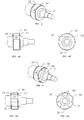
- a transverse-pole AC inductor type rotating dynamoelectric machine constructed in accordance with the principles of the present invention is shown.
- the machine generally denoted 10, includes a stationary stator assembly 12 surrounding a rotatable, coil-less rotor 14.
- a surrounding housing or frame 16 peripherally encloses stator assembly 12.
- End shields 15 are secured by threaded fasteners 17 to each end of housing 16 and rotatably support ends of rotor 14.
- Stator assembly 12 includes an internal spool-like support structure 30.
- Support structure 30 has a central, generally cylindrical portion or tube 32 which is coaxial with longitudinal axis 18 and defines an interior, longitudinally extending, central passageway for receiving rotor 14.
- Field (or DC exitation) windings 34 are coiled about and supported by the exterior surface of tube 32.
- Stator support structure 30 also includes a pair of end portions or plates 36 extending radially outward from the ends of tube 32. End portions 36 serve to mount and precisely position a plurality of circumferentially distributed, U-shaped (also referred to as C- or arch-shaped) armature core elements 38.
- Each armature core element 38 is preferably provided with an individual AC armature coil 40 wound about, and supported by a generally longitudinally extending base portion 42 of the armature element.
- Legs 44 extend radially inward from each end of base portion 42 of armature element 38.
- Armature core elements 38 are made of magnetic material while support structure 30 is composed of non-magnetic material, for example, aluminium. Electrical leads 46 from the field and armature coils extend through a suitable connector 48 mounted in one of the end shields 15.
- Stator assembly 12 is preferably positioned and mounted within housing 16 by threaded fasteners 52 extending through radial extensions 54 of end portions 36 into intermediate mounting supports 56.
- Mounting supports 56 are circumferentially distributed about and secured to the interior of housing 16. This preferred mounting arrangement is described in detail in co-pending, commonly owned U.S. patent application Serial No. 07/395,032 filed August 17, 1989 entitled "Stator Mounting Arrangement”.
- Rotor 14 extends along and is coaxial with the longitudinal axis 18.
- the rotor preferably has a solid one-piece construction and is supported by bearings 20, at each end of rotor shaft 22. Bearings 20 are mounted within end shields 15.
- Rotor 14 has a central cylindrical body portion 24 provided with circumferentially spaced, axially extending surface recesses or cutouts 26 at the ends thereof, which define a desired number or set of lobes or salient poles 28 at each end of the homopolar transverse pole rotor.
- inner shrouds 29 and outer shrouds 31 are provided on either side of each set of salient poles 28 to reduce windage losses.
- the rotor can be constructed of any available magnetic material, for example, carbon steel.
- Operation of machine 10 is typical of synchronous AC machines in that, if electric current is applied to the field windings 34, and the rotor 14 is rotated by some external means, voltage will be induced in the armature windings 40 in the manner of a generator. Similarly, if the armature windings are energized in a fashion such as to produce a rotating flux wave at the gap 50, which exists between the radially innermost ends of armature elements 38 and the rotor pole surfaces 28, as is done in polyphase, AC synchronous machines, the rotor 14 of the machine will be urged to follow the armature flux wave and rotate in the manner of an electric motor.
- FIG. 2 A preferred embodiment of the improved rotor 14 of the present invention is illustrated in Figure 2.
- a set of circumferentially spaced, axially extending salient poles 28 located on each end of the central cylindrical body 24 is a set of circumferentially spaced, axially extending salient poles 28.
- the poles in each set are separated by interpole recesses 26, preferably having flat landings or bases 58.
- interpole recesses 26 preferably having flat landings or bases 58.
- three equally spaced salient poles 28 are shown in each set, the number, spacing and other characteristics of the poles may vary in accordance with machine design specifications.
- an outer shroud 31 is provided at the axially outer end of each set of salient poles 28.
- Shroud 31 closes the outer end of recesses 26 blocking axial air flow into the recesses and thereby reducing windage losses.
- Shroud 31 is formed from the same piece of material as cylindrical body 24 and poles 28. This integral, one-piece construction, allows the rotor to achieve high speeds and high horsepowers without the risk of pieces or parts separating from the rotor body during such operation.
- Shroud 31 preferably has a disc-like shape.
- the outer circumferential surface 60 of shroud 31 is machined down such that the pole face extends radially beyond the shroud 31.
- the relief 60 formed along the outer edge of shroud 31 serves to ensure magnetic centering of the rotor as described in greater detail hereinafter.
- shroud 29 is provided at the axially inner end of each set of salient poles 28.
- shroud 29 comprises the axially outer portion of central cylindrical body 24.
- a circumferential slot or relief 62 is machined along the outer edge of shroud 29 so that the outer faces of poles 28 extend radially farther than inner shroud 29.
- Inner shroud 29 is, of course, integral with the rest of rotor 14.
- Accentuated pole tips 64 extend farther in the radial direction than shrouds 29 or 31 and are therefore nearer to the inner faces of armature cores 38. This is significant because the shrouds, being formed of the same material as poles 28, are magnetic. The accentuated pole tips prevent the shrouds from being attracted into the magnetic field under the armature cores and thus the rotor stays on its magnetic center. This feature allows the rotor to be mounted without a thrust bearing and eliminates unwanted axial movement and forces which might lead to a shortening of the bearing life. The accentuation of the pole tips also reduces flux leakage.
- the amount of material machined away along the outer surface of inner shroud 29 and outer shroud 31 may vary. In a prototype machine, approximately 4% of the rotor radius (i.e. the radius of central cylindrical body 24) was machined away.
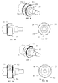
- an outer cylindrical surface can be produced in the pole region of the rotor by filling interpole recesses 26 with non-magnetic material.
- Figures 4-9 illustrate alternate approaches for achieving such enhanced benefits.
- Figures 4, 4A and 4B depict an embodiment in which the regions between salient poles 28 and opposed faces of shrouds 29 and 31, are filled with a non-magnetic material 64 which can be deposited by a plasma-arc hot wire welding process. The assembly can then be machined into the desired cylindrical shape. The bond between the magnetic material of the rotor and the non-magnetic material 64 should be strong enough to withstand the mechanical centrifugal forces experienced by the rotor at high speeds.
- FIGS 5, 5A and 5B illustrate a similar construction employing partially machined blocks or inserts 66 which are inserted into the interpole spaces and held there by mechanical fasteners 68.
- Fasteners 68 extend axially through the inner and outer shrouds and the sandwiched insert 66 to securely fasten the non-magnetic inserts to the rotor. After inserts 66 are so mounted and fastened, the outer surface in the pole area can be machined to the desired smooth cylindrical shape.
- dove tail connections are used to secure non-magnetic filler pieces 70 within the interpole recesses.
- Each filler piece 70 is premachined with a dove tail 72 which can be inserted into a cooperating dove tail slot 74 premachined along the base 58 of an interpole recess.
- the filler piece 70 can be locked in place with keys or by upsetting the outer end of the dove tail material, in a fashion well known in the art.
- the outer surface of the filler pieces 70 can then be machined to the desired final cylindrical configuration.
- Figures 7, 7A and 7B illustrate a similar embodiment, except that a higher strength "christmas tree" slot type connection 76 is used to hold the interpole pieces 78 in place.
- FIG 8, 8A and 8B show another approach for securing non-magnetic interpole pieces 80 to the magnetic rotor, using glass-resin soaked banding.
- Each interpole piece 80 is premachined to shape and provided with reduced radius axially extending ears 82 at each end thereof.
- Interpole piece 80 is then inserted in a recess between the inner shroud 29 and outer shroud 31.
- Circumferentially extending grooves 84, aligned with ears 82 are machined into the outer surface of salient poles 28.
- a pair of circumferential bands 86 are located in slots 84 and extend over the outer surface of ears 82.
- Bands 86 are preferably composed of glass-resin soaked banding under tension and are baked to cure. Bands 86 thus firmly secure the filler pieces 80 in the interpole recesses.
- Figures 9, 9A and 9B illustrate a similar mounting approach, without shrouds.
Landscapes
- Engineering & Computer Science (AREA)
- Power Engineering (AREA)
- Iron Core Of Rotating Electric Machines (AREA)
- Synchronous Machinery (AREA)
- Insulation, Fastening Of Motor, Generator Windings (AREA)
- Manufacture Of Motors, Generators (AREA)
- Motor Or Generator Cooling System (AREA)
Abstract
Claims (14)
- Rotor (14) destiné à une machine dynamo-électrique (10) présentant des pertes par ventilation réduite, le rotor (14) étant de construction à pôle transversal, saillant, homopolaire, sans enroulement, rotatif autour d'un axe longitudinal central (18), le rotor (14) comprenant : un corps cylindrique plein (24), s'étendant axialement, et une première série de pôles saillants (28), espacés circonférenciellement et s'étendant axialement avec des évidements (26) espacés circonférenciellement entre ceux-ci sur une extrémité du corps cylindrique (24) et une seconde série de pôles saillants (28) espacés circonférentiellement, s'étendant axialement avec des évidements (26) entre ceux-ci sur l'autre extrémité du corps cylindrique (24), le rotor (14) comportant :
des moyens d'enveloppe de protection interne s'étendant transversalement (29), situés sur les extrémités internes axialement, des première et seconde séries de pôles saillants (28) destinés à envelopper axialement les extrémités internes des évidements (26) ;
des moyens d'enveloppe de protection externe s'étendant transversalement (31) situés sur les extrémités externes axialement des première et seconde séries de pôles saillants (28) destinés à envelopper axialement les extrémités externes des évidements (26) ; et
des moyens d'arbre (22) s'étendant axialement vers l'extérieur à partir des moyens d'enveloppe de protection externe (31) permettant le montage du rotor (14) pour la rotation autour de l'axe longitudinal (18) ;
le rotor étant caractérisé par les moyens de protection d'enveloppe externe et interne (29, 31) et les pôles saillants (28) étant solidaires du corps cylindrique central (24) ; et
les moyens d'enveloppe de protection solidaires (29, 31), les pôles saillants (28) et le corps cylindrique (24) étant constitués de matériaux magnétiques, et une dépouille (60, 62) étant formée le long d'un bord externe radialement des moyens d'enveloppe de protection externe (31) et des moyens d'enveloppe de protection interne (29) de telle sorte que les pôles saillants (28) s'étendent radialement vers l'extérieur sur une plus grande distance que les moyens d'enveloppe de protection externe et interne (31, 29) pour faciliter le centrage magnétique du rotor (14). - Rotor (14) selon la revendication 1, dans lequel les moyens d'enveloppe de protection externe (31) comprennent un élément discoïde, de façon générale plat.
- Rotor (14) selon la revendication 1, dans lequel les moyens d'enveloppe de protection interne (29) s'étendent radialement vers l'extérieur sur une plus grande distance que le corps cylindrique central (24).
- Rotor (14) selon la revendication 1 ou 3, comprenant de plus un matériau non magnétique remplissant les évidements (26) et formant une surface cylindrique externe avec chaque série de pôles saillants (28).
- Rotor (14) selon la revendication 4, dans lequel le matériau non magnétique (64) est déposé dans les évidements (26) par un procédé de soudage à fil chaud arc-plasma et présente une surface cylindrique externe usinée.
- Rotor (14) selon la revendication 4, dans lequel le matériau non magnétique comprend des inserts ou éléments rapportés usinés (66), et comprenant de plus des moyens de fixation pour assujettir les inserts (66) dans les évidements (26).
- Rotor (14) selon la revendication 6, dans lequel les moyens de fixation comprennent des attaches (68) s'étendant à travers les moyens d'enveloppe de protection interne (29), un insert (66), et les moyens d'enveloppe de protection externe (31).
- Rotor (14) selon la revendication 6, dans lequel les moyens de fixation comprennent un raccordement en queue d'aronde (72, 74).
- Rotor (14) selon la revendication 8, dans lequel le raccordement ou liaison présente une configuration en coupe transversale en forme de sapin de Noël (76).
- Rotor (14) selon la revendication 6, dans lequel les moyens de fixation comprennent un bandage circonférenciel.
- Rotor (14) selon la revendication 10, dans lequel le bandage comprend une paire de bandes (86) imprégnées de résine de verre durcie, sous tension, s'étendant au niveau des inserts de chaque série à proximité des extrémités externes axialement et internes axialement, respectivement, des inserts.
- Rotor (14) selon la revendication 1, dans lequel chaque moyen d'enveloppe interne (29) comprend une portion d'extrémité externe axialement du corps cylindrique central (24) avec une dépouille s'étendant circonférenciellement (62), usinée dans la portion.
- Rotor (14) selon la revendication 4, en combinaison avec un ensemble stator (12), l'ensemble stator (12) comprenant une structure de support non magnétique de type bobine (30), comportant une portion centrale allongée creuse (32) s'étendant sur le rotor (14), cette structure en forme de bobine (30) présentant des portions d'extrémité espacées axialement (36) qui s'étendent radialement vers l'extérieur par rapport à l'axe longitudinal (18) à partir des extrémités respectives de la portion centrale (32) et une pluralité de noyaux d'induit s'étendant de façon générale longitudinalement, généralement en forme de U, répartis circonférentiellement (38) supportés par les portions d'extrémité (36) de la structure en forme de bobine (30).
- Combinaison de la revendication (13) dans laquelle l'ensemble stator (12) comprend de plus un enroulement de champ (34) enroulé sur la portion centrale (32) de la structure en forme de bobine (30), et
dans lequel les moyens d'arbre (22) sont solidaires des moyens d'enveloppe de protection externe (31).
Applications Claiming Priority (3)
| Application Number | Priority Date | Filing Date | Title |
|---|---|---|---|
| US07/402,070 US5001378A (en) | 1989-09-01 | 1989-09-01 | Rotor with reduced windage losses |
| US402070 | 1989-09-01 | ||
| PCT/US1990/003741 WO1991003859A1 (fr) | 1989-09-01 | 1990-07-05 | Rotor a pertes d'enroulement reduites |
Publications (3)
| Publication Number | Publication Date |
|---|---|
| EP0489859A4 EP0489859A4 (fr) | 1992-02-20 |
| EP0489859A1 EP0489859A1 (fr) | 1992-06-17 |
| EP0489859B1 true EP0489859B1 (fr) | 1994-11-30 |
Family
ID=23590388
Family Applications (1)
| Application Number | Title | Priority Date | Filing Date |
|---|---|---|---|
| EP90914331A Expired - Lifetime EP0489859B1 (fr) | 1989-09-01 | 1990-07-05 | Rotor a pertes par ventilation reduites |
Country Status (9)
| Country | Link |
|---|---|
| US (1) | US5001378A (fr) |
| EP (1) | EP0489859B1 (fr) |
| JP (1) | JPH0759137B2 (fr) |
| KR (1) | KR920702063A (fr) |
| AU (1) | AU628670B2 (fr) |
| BR (1) | BR9007319A (fr) |
| CA (1) | CA2044278A1 (fr) |
| DE (1) | DE69014642T2 (fr) |
| WO (1) | WO1991003859A1 (fr) |
Families Citing this family (19)
| Publication number | Priority date | Publication date | Assignee | Title |
|---|---|---|---|---|
| US5142182A (en) * | 1991-06-14 | 1992-08-25 | General Electric Company | Adjustable width caps for insulating series loops on bar wound armatures in electrical systems |
| US5196749A (en) * | 1991-09-23 | 1993-03-23 | Rem Technologies, Inc. | Stator support and positioning structure for a dynamoelectric machine |
| US5196752A (en) * | 1991-10-31 | 1993-03-23 | Rem Technologies, Inc. | System for supporting conductors for use in a dynamoelectric machine |
| US5344443A (en) * | 1992-09-17 | 1994-09-06 | Rem Technologies, Inc. | Heart pump |
| US5317227A (en) * | 1992-12-08 | 1994-05-31 | Rem Technologies, Inc. | Rotor with hollow cylindrical permanent magnet |
| FR2710466B1 (fr) * | 1993-09-21 | 1995-11-10 | Gec Alsthom Transport Sa | Rotor de machine synchrone. |
| FR2728739B1 (fr) * | 1994-12-22 | 1997-01-17 | Renault | Generatrice haute vitesse a champ magnetique axial |
| FR2746250B1 (fr) * | 1996-03-13 | 1999-08-06 | Actionneur magnetique pourvu d'une paroi de separation | |
| US5703421A (en) * | 1996-05-24 | 1997-12-30 | The United States Of America As Represented By The Secretary Of The Air Force | Reluctance generator/motor cooling |
| US5929548A (en) * | 1997-09-08 | 1999-07-27 | Active Power, Inc. | High inertia inductor-alternator |
| US5898246A (en) * | 1998-03-13 | 1999-04-27 | The United States Of America As Represented By The Secretary Of The Air Force | Control of reluctance dynamoelectric machine cooling fluid |
| US20100019604A1 (en) * | 2003-05-27 | 2010-01-28 | General Electric Company | Methods and apparatus for assembling homopolar inductor alternators including superconducting windings |
| US20040239201A1 (en) * | 2003-05-27 | 2004-12-02 | General Electric Company | Methods and apparatus for assembling homopolar inductor alternators including superconducting windings |
| US20060043801A1 (en) * | 2004-08-27 | 2006-03-02 | Caterpillar Inc. | Liquid cooled switched reluctance electric machine |
| EP2605379B1 (fr) | 2011-12-14 | 2015-04-29 | GE Jenbacher GmbH & Co. OG | Système et procédé de refroidissement de machine dynamoélectrique |
| US9509183B2 (en) | 2013-07-19 | 2016-11-29 | General Electric Company | Rotor with non-cylindrical surface for dynamoelectric machine |
| US9520751B2 (en) | 2013-07-24 | 2016-12-13 | General Electric Company | System and method for smoothing a salient rotor in electrical machines |
| JP6250159B2 (ja) * | 2014-06-18 | 2017-12-20 | 三菱電機株式会社 | 交流発電機のスリップリング装置 |
| CN120090405B (zh) * | 2025-05-06 | 2025-07-08 | 成都微精电机股份公司 | 一种无框力矩电机 |
Family Cites Families (16)
| Publication number | Priority date | Publication date | Assignee | Title |
|---|---|---|---|---|
| BE569575A (fr) * | ||||
| US3258620A (en) * | 1966-06-28 | High speed rotor pole enclosure | ||
| US3157806A (en) * | 1959-11-05 | 1964-11-17 | Bbc Brown Boveri & Cie | Synchronous machine with salient poles |
| US3321652A (en) * | 1963-12-23 | 1967-05-23 | North American Aviation Inc | Dynamo-electric machine |
| US3535572A (en) * | 1968-11-15 | 1970-10-20 | John De Rugeris | Alternator having rotatable magnetic field and armature structures |
| US3737696A (en) * | 1971-09-16 | 1973-06-05 | Gen Electric | High speed homopolar inductor generator with straight winding construction |
| DE2317500A1 (de) * | 1973-04-04 | 1974-10-10 | Siemens Ag | Elektrische synchronmaschine homopolarer bauart |
| US4024628A (en) * | 1976-06-22 | 1977-05-24 | Crites Donald M | Process for manufacturing a two-pole solid rotor |
| US4128777A (en) * | 1976-09-24 | 1978-12-05 | General Electric Company | Armature core wrapped with irradiation curable glass banding |
| US4302693A (en) * | 1978-12-26 | 1981-11-24 | The Garrett Corporation | Wedge shaped permanent magnet rotor assembly with magnet cushions |
| US4423344A (en) * | 1981-02-23 | 1983-12-27 | Litton Industrial Products, Inc. | Liquid cooled eddy current coupling having rotor extension ring |
| US4445056A (en) * | 1981-11-02 | 1984-04-24 | Litton Industrial Products, Inc. | Means for improving the operation of liquid filled electric motors |
| US4617485A (en) * | 1983-12-19 | 1986-10-14 | Nippondenso Co., Ltd. | Rotor of alternator mounted on vehicle |
| US4795936A (en) * | 1986-08-26 | 1989-01-03 | Midwest Dynamometer & Engineering Co. | Driven rotary shaft system using permanent magnets |
| US4786834A (en) * | 1987-07-06 | 1988-11-22 | Rem Technologies, Inc. | Stator assembly for dynamoelectric machine |
| US4864176A (en) * | 1988-07-29 | 1989-09-05 | Rem Technologies, Inc. | Stator support structure with stamped end plates |
-
1989
- 1989-09-01 US US07/402,070 patent/US5001378A/en not_active Expired - Fee Related
-
1990
- 1990-07-05 KR KR1019910701492A patent/KR920702063A/ko not_active Ceased
- 1990-07-05 DE DE69014642T patent/DE69014642T2/de not_active Expired - Fee Related
- 1990-07-05 BR BR909007319A patent/BR9007319A/pt unknown
- 1990-07-05 AU AU64281/90A patent/AU628670B2/en not_active Ceased
- 1990-07-05 WO PCT/US1990/003741 patent/WO1991003859A1/fr not_active Ceased
- 1990-07-05 EP EP90914331A patent/EP0489859B1/fr not_active Expired - Lifetime
- 1990-07-05 CA CA002044278A patent/CA2044278A1/fr not_active Abandoned
- 1990-08-31 JP JP2232323A patent/JPH0759137B2/ja not_active Expired - Lifetime
Also Published As
| Publication number | Publication date |
|---|---|
| CA2044278A1 (fr) | 1991-03-02 |
| EP0489859A1 (fr) | 1992-06-17 |
| BR9007319A (pt) | 1992-04-21 |
| DE69014642D1 (de) | 1995-01-12 |
| AU6428190A (en) | 1991-04-08 |
| AU628670B2 (en) | 1992-09-17 |
| JPH0759137B2 (ja) | 1995-06-21 |
| KR920702063A (ko) | 1992-08-12 |
| DE69014642T2 (de) | 1995-06-01 |
| JPH0393438A (ja) | 1991-04-18 |
| WO1991003859A1 (fr) | 1991-03-21 |
| US5001378A (en) | 1991-03-19 |
| EP0489859A4 (fr) | 1992-02-20 |
Similar Documents
| Publication | Publication Date | Title |
|---|---|---|
| EP0489859B1 (fr) | Rotor a pertes par ventilation reduites | |
| CA1278015C (fr) | Stator de machine dynamoelectrique | |
| AU612891B2 (en) | Stator support structure with stamped end plates | |
| US4959578A (en) | Dual rotor axial air gap induction motor | |
| EP0495582B1 (fr) | Machine en forme de disque, à haut rendement et faible réactance comprenant un stator et un rotor | |
| AU632835B2 (en) | Stator mounting arrangement | |
| EP0412645A1 (fr) | Ventilateur de refroidissement à double face pour une machine dynamo-électrique | |
| GB2281665A (en) | Mounting magnets in a rotor for an AC generator | |
| US5886449A (en) | Electrical machine | |
| US20230216357A1 (en) | Stator for an electrical axial flux machine and electric axial flux machine | |
| JPH06511132A (ja) | ダイナモ電気機械の固定子支持配列構成 | |
| US20150171673A1 (en) | System and method for retaining rotor structure in synchronous reluctance machine | |
| US5317227A (en) | Rotor with hollow cylindrical permanent magnet | |
| AU603448B2 (en) | Stator assembly for dynamoelectric machine | |
| JP2021522767A (ja) | 回転電気機械の為の回転子 |
Legal Events
| Date | Code | Title | Description |
|---|---|---|---|
| PUAI | Public reference made under article 153(3) epc to a published international application that has entered the european phase |
Free format text: ORIGINAL CODE: 0009012 |
|
| 17P | Request for examination filed |
Effective date: 19911023 |
|
| AK | Designated contracting states |
Kind code of ref document: A1 Designated state(s): DE FR GB IT SE |
|
| 17Q | First examination report despatched |
Effective date: 19930702 |
|
| GRAA | (expected) grant |
Free format text: ORIGINAL CODE: 0009210 |
|
| AK | Designated contracting states |
Kind code of ref document: B1 Designated state(s): DE FR GB IT SE |
|
| REF | Corresponds to: |
Ref document number: 69014642 Country of ref document: DE Date of ref document: 19950112 |
|
| ITF | It: translation for a ep patent filed | ||
| ET | Fr: translation filed | ||
| PGFP | Annual fee paid to national office [announced via postgrant information from national office to epo] |
Ref country code: SE Payment date: 19950626 Year of fee payment: 6 |
|
| PGFP | Annual fee paid to national office [announced via postgrant information from national office to epo] |
Ref country code: FR Payment date: 19950629 Year of fee payment: 6 |
|
| PGFP | Annual fee paid to national office [announced via postgrant information from national office to epo] |
Ref country code: GB Payment date: 19950705 Year of fee payment: 6 |
|
| PGFP | Annual fee paid to national office [announced via postgrant information from national office to epo] |
Ref country code: DE Payment date: 19950811 Year of fee payment: 6 |
|
| PLBE | No opposition filed within time limit |
Free format text: ORIGINAL CODE: 0009261 |
|
| STAA | Information on the status of an ep patent application or granted ep patent |
Free format text: STATUS: NO OPPOSITION FILED WITHIN TIME LIMIT |
|
| 26N | No opposition filed | ||
| PG25 | Lapsed in a contracting state [announced via postgrant information from national office to epo] |
Ref country code: GB Effective date: 19960705 |
|
| PG25 | Lapsed in a contracting state [announced via postgrant information from national office to epo] |
Ref country code: SE Effective date: 19960706 |
|
| GBPC | Gb: european patent ceased through non-payment of renewal fee |
Effective date: 19960705 |
|
| PG25 | Lapsed in a contracting state [announced via postgrant information from national office to epo] |
Ref country code: FR Effective date: 19970328 |
|
| PG25 | Lapsed in a contracting state [announced via postgrant information from national office to epo] |
Ref country code: DE Effective date: 19970402 |
|
| EUG | Se: european patent has lapsed |
Ref document number: 90914331.5 |
|
| REG | Reference to a national code |
Ref country code: FR Ref legal event code: ST |
|
| PG25 | Lapsed in a contracting state [announced via postgrant information from national office to epo] |
Ref country code: IT Free format text: LAPSE BECAUSE OF NON-PAYMENT OF DUE FEES Effective date: 20050705 |