EP0489867B1 - Verfahren und vorrichtung um durch anwendung von hitze feststoffabfall umweltunschädlich zu machen - Google Patents
Verfahren und vorrichtung um durch anwendung von hitze feststoffabfall umweltunschädlich zu machen Download PDFInfo
- Publication number
- EP0489867B1 EP0489867B1 EP90914582A EP90914582A EP0489867B1 EP 0489867 B1 EP0489867 B1 EP 0489867B1 EP 90914582 A EP90914582 A EP 90914582A EP 90914582 A EP90914582 A EP 90914582A EP 0489867 B1 EP0489867 B1 EP 0489867B1
- Authority
- EP
- European Patent Office
- Prior art keywords
- effluvia
- solid waste
- chamber
- waste material
- reaction chamber
- Prior art date
- Legal status (The legal status is an assumption and is not a legal conclusion. Google has not performed a legal analysis and makes no representation as to the accuracy of the status listed.)
- Expired - Lifetime
Links
- 239000000463 material Substances 0.000 title claims abstract description 111
- 239000002910 solid waste Substances 0.000 title claims abstract description 78
- 238000000034 method Methods 0.000 title claims description 74
- 238000006243 chemical reaction Methods 0.000 claims abstract description 70
- 239000002893 slag Substances 0.000 claims abstract description 64
- QVGXLLKOCUKJST-UHFFFAOYSA-N atomic oxygen Chemical compound [O] QVGXLLKOCUKJST-UHFFFAOYSA-N 0.000 claims abstract description 45
- 239000001301 oxygen Substances 0.000 claims abstract description 45
- 229910052760 oxygen Inorganic materials 0.000 claims abstract description 45
- 239000000470 constituent Substances 0.000 claims abstract description 38
- 230000005284 excitation Effects 0.000 claims abstract description 37
- 239000000203 mixture Substances 0.000 claims abstract description 27
- 230000015572 biosynthetic process Effects 0.000 claims abstract description 12
- 230000007613 environmental effect Effects 0.000 claims abstract description 7
- 239000011236 particulate material Substances 0.000 claims abstract description 6
- 230000008569 process Effects 0.000 claims description 64
- 239000002699 waste material Substances 0.000 claims description 35
- 230000005855 radiation Effects 0.000 claims description 29
- 230000001427 coherent effect Effects 0.000 claims description 25
- 238000001816 cooling Methods 0.000 claims description 17
- 229910000831 Steel Inorganic materials 0.000 claims description 14
- 239000007788 liquid Substances 0.000 claims description 14
- 239000010959 steel Substances 0.000 claims description 14
- 239000002956 ash Substances 0.000 claims description 13
- 239000012717 electrostatic precipitator Substances 0.000 claims description 13
- XLYOFNOQVPJJNP-UHFFFAOYSA-N water Substances O XLYOFNOQVPJJNP-UHFFFAOYSA-N 0.000 claims description 12
- 238000010438 heat treatment Methods 0.000 claims description 10
- 239000010881 fly ash Substances 0.000 claims description 9
- 239000002245 particle Substances 0.000 claims description 6
- 238000002156 mixing Methods 0.000 claims description 3
- 238000001914 filtration Methods 0.000 claims description 2
- 239000011368 organic material Substances 0.000 claims 2
- 239000013528 metallic particle Substances 0.000 claims 1
- 239000007789 gas Substances 0.000 abstract description 22
- 239000012716 precipitator Substances 0.000 description 25
- 238000002485 combustion reaction Methods 0.000 description 20
- CURLTUGMZLYLDI-UHFFFAOYSA-N Carbon dioxide Chemical compound O=C=O CURLTUGMZLYLDI-UHFFFAOYSA-N 0.000 description 18
- 239000000047 product Substances 0.000 description 18
- 239000003245 coal Substances 0.000 description 17
- 230000003287 optical effect Effects 0.000 description 14
- 239000001569 carbon dioxide Substances 0.000 description 13
- 229910002092 carbon dioxide Inorganic materials 0.000 description 13
- RAHZWNYVWXNFOC-UHFFFAOYSA-N Sulphur dioxide Chemical compound O=S=O RAHZWNYVWXNFOC-UHFFFAOYSA-N 0.000 description 12
- 229910052751 metal Inorganic materials 0.000 description 11
- 239000002184 metal Substances 0.000 description 11
- 230000009466 transformation Effects 0.000 description 11
- XKRFYHLGVUSROY-UHFFFAOYSA-N Argon Chemical compound [Ar] XKRFYHLGVUSROY-UHFFFAOYSA-N 0.000 description 8
- 239000013618 particulate matter Substances 0.000 description 8
- 239000007858 starting material Substances 0.000 description 8
- OKTJSMMVPCPJKN-UHFFFAOYSA-N Carbon Chemical compound [C] OKTJSMMVPCPJKN-UHFFFAOYSA-N 0.000 description 7
- 150000002739 metals Chemical class 0.000 description 7
- 239000002023 wood Substances 0.000 description 7
- 229910001369 Brass Inorganic materials 0.000 description 6
- 229910052782 aluminium Inorganic materials 0.000 description 6
- XAGFODPZIPBFFR-UHFFFAOYSA-N aluminium Chemical compound [Al] XAGFODPZIPBFFR-UHFFFAOYSA-N 0.000 description 6
- 239000010951 brass Substances 0.000 description 6
- 239000004291 sulphur dioxide Substances 0.000 description 6
- HCHKCACWOHOZIP-UHFFFAOYSA-N Zinc Chemical compound [Zn] HCHKCACWOHOZIP-UHFFFAOYSA-N 0.000 description 5
- 239000006227 byproduct Substances 0.000 description 5
- 229910052799 carbon Inorganic materials 0.000 description 5
- 239000000919 ceramic Substances 0.000 description 5
- CPBQJMYROZQQJC-UHFFFAOYSA-N helium neon Chemical compound [He].[Ne] CPBQJMYROZQQJC-UHFFFAOYSA-N 0.000 description 5
- 229910052725 zinc Inorganic materials 0.000 description 5
- 239000011701 zinc Substances 0.000 description 5
- 241000209094 Oryza Species 0.000 description 4
- 235000007164 Oryza sativa Nutrition 0.000 description 4
- 229910052786 argon Inorganic materials 0.000 description 4
- 239000011521 glass Substances 0.000 description 4
- 210000002381 plasma Anatomy 0.000 description 4
- 238000010992 reflux Methods 0.000 description 4
- 235000009566 rice Nutrition 0.000 description 4
- AKEJUJNQAAGONA-UHFFFAOYSA-N sulfur trioxide Chemical compound O=S(=O)=O AKEJUJNQAAGONA-UHFFFAOYSA-N 0.000 description 4
- 230000001131 transforming effect Effects 0.000 description 4
- UGFAIRIUMAVXCW-UHFFFAOYSA-N Carbon monoxide Chemical compound [O+]#[C-] UGFAIRIUMAVXCW-UHFFFAOYSA-N 0.000 description 3
- VYPSYNLAJGMNEJ-UHFFFAOYSA-N Silicium dioxide Chemical compound O=[Si]=O VYPSYNLAJGMNEJ-UHFFFAOYSA-N 0.000 description 3
- 229910052785 arsenic Inorganic materials 0.000 description 3
- RQNWIZPPADIBDY-UHFFFAOYSA-N arsenic atom Chemical compound [As] RQNWIZPPADIBDY-UHFFFAOYSA-N 0.000 description 3
- 230000000694 effects Effects 0.000 description 3
- 239000003546 flue gas Substances 0.000 description 3
- 231100001261 hazardous Toxicity 0.000 description 3
- 239000002920 hazardous waste Substances 0.000 description 3
- 229910001385 heavy metal Inorganic materials 0.000 description 3
- 239000010814 metallic waste Substances 0.000 description 3
- 238000012545 processing Methods 0.000 description 3
- 239000007787 solid Substances 0.000 description 3
- 239000000126 substance Substances 0.000 description 3
- 238000012360 testing method Methods 0.000 description 3
- PFNQVRZLDWYSCW-UHFFFAOYSA-N (fluoren-9-ylideneamino) n-naphthalen-1-ylcarbamate Chemical compound C12=CC=CC=C2C2=CC=CC=C2C1=NOC(=O)NC1=CC=CC2=CC=CC=C12 PFNQVRZLDWYSCW-UHFFFAOYSA-N 0.000 description 2
- RZVAJINKPMORJF-UHFFFAOYSA-N Acetaminophen Chemical compound CC(=O)NC1=CC=C(O)C=C1 RZVAJINKPMORJF-UHFFFAOYSA-N 0.000 description 2
- RYGMFSIKBFXOCR-UHFFFAOYSA-N Copper Chemical compound [Cu] RYGMFSIKBFXOCR-UHFFFAOYSA-N 0.000 description 2
- QAOWNCQODCNURD-UHFFFAOYSA-N Sulfuric acid Chemical compound OS(O)(=O)=O QAOWNCQODCNURD-UHFFFAOYSA-N 0.000 description 2
- 230000002411 adverse Effects 0.000 description 2
- 239000005388 borosilicate glass Substances 0.000 description 2
- 239000011449 brick Substances 0.000 description 2
- 238000004364 calculation method Methods 0.000 description 2
- 239000011651 chromium Substances 0.000 description 2
- 239000000571 coke Substances 0.000 description 2
- 229910052802 copper Inorganic materials 0.000 description 2
- 239000010949 copper Substances 0.000 description 2
- 230000007812 deficiency Effects 0.000 description 2
- 239000000446 fuel Substances 0.000 description 2
- 239000010438 granite Substances 0.000 description 2
- 239000008187 granular material Substances 0.000 description 2
- 230000000977 initiatory effect Effects 0.000 description 2
- 239000002906 medical waste Substances 0.000 description 2
- 239000012768 molten material Substances 0.000 description 2
- 238000012544 monitoring process Methods 0.000 description 2
- 150000002894 organic compounds Chemical class 0.000 description 2
- 230000001590 oxidative effect Effects 0.000 description 2
- BASFCYQUMIYNBI-UHFFFAOYSA-N platinum Chemical compound [Pt] BASFCYQUMIYNBI-UHFFFAOYSA-N 0.000 description 2
- 239000005297 pyrex Substances 0.000 description 2
- 239000011150 reinforced concrete Substances 0.000 description 2
- 239000011669 selenium Substances 0.000 description 2
- 239000011343 solid material Substances 0.000 description 2
- 235000010269 sulphur dioxide Nutrition 0.000 description 2
- 230000002459 sustained effect Effects 0.000 description 2
- -1 zinc and lead Chemical class 0.000 description 2
- VYZAMTAEIAYCRO-UHFFFAOYSA-N Chromium Chemical compound [Cr] VYZAMTAEIAYCRO-UHFFFAOYSA-N 0.000 description 1
- 241000196324 Embryophyta Species 0.000 description 1
- 239000004677 Nylon Substances 0.000 description 1
- CBENFWSGALASAD-UHFFFAOYSA-N Ozone Chemical compound [O-][O+]=O CBENFWSGALASAD-UHFFFAOYSA-N 0.000 description 1
- 241000233805 Phoenix Species 0.000 description 1
- OAICVXFJPJFONN-UHFFFAOYSA-N Phosphorus Chemical compound [P] OAICVXFJPJFONN-UHFFFAOYSA-N 0.000 description 1
- BUGBHKTXTAQXES-UHFFFAOYSA-N Selenium Chemical compound [Se] BUGBHKTXTAQXES-UHFFFAOYSA-N 0.000 description 1
- BQCADISMDOOEFD-UHFFFAOYSA-N Silver Chemical compound [Ag] BQCADISMDOOEFD-UHFFFAOYSA-N 0.000 description 1
- 229910052788 barium Inorganic materials 0.000 description 1
- DSAJWYNOEDNPEQ-UHFFFAOYSA-N barium atom Chemical compound [Ba] DSAJWYNOEDNPEQ-UHFFFAOYSA-N 0.000 description 1
- 239000010882 bottom ash Substances 0.000 description 1
- 229910052793 cadmium Inorganic materials 0.000 description 1
- BDOSMKKIYDKNTQ-UHFFFAOYSA-N cadmium atom Chemical compound [Cd] BDOSMKKIYDKNTQ-UHFFFAOYSA-N 0.000 description 1
- 229910002091 carbon monoxide Inorganic materials 0.000 description 1
- 239000003575 carbonaceous material Substances 0.000 description 1
- 229910010293 ceramic material Inorganic materials 0.000 description 1
- 229910052804 chromium Inorganic materials 0.000 description 1
- 239000010960 cold rolled steel Substances 0.000 description 1
- 239000010849 combustible waste Substances 0.000 description 1
- 239000000567 combustion gas Substances 0.000 description 1
- 238000009833 condensation Methods 0.000 description 1
- 230000005494 condensation Effects 0.000 description 1
- 238000010276 construction Methods 0.000 description 1
- 239000004035 construction material Substances 0.000 description 1
- 239000000356 contaminant Substances 0.000 description 1
- 239000010730 cutting oil Substances 0.000 description 1
- 230000007423 decrease Effects 0.000 description 1
- 150000002013 dioxins Chemical class 0.000 description 1
- 230000005686 electrostatic field Effects 0.000 description 1
- 238000013028 emission testing Methods 0.000 description 1
- 239000002360 explosive Substances 0.000 description 1
- PCHJSUWPFVWCPO-UHFFFAOYSA-N gold Chemical compound [Au] PCHJSUWPFVWCPO-UHFFFAOYSA-N 0.000 description 1
- 229910052737 gold Inorganic materials 0.000 description 1
- 239000010931 gold Substances 0.000 description 1
- 230000003179 granulation Effects 0.000 description 1
- 238000005469 granulation Methods 0.000 description 1
- 230000005484 gravity Effects 0.000 description 1
- 239000000383 hazardous chemical Substances 0.000 description 1
- 239000003779 heat-resistant material Substances 0.000 description 1
- 239000001307 helium Substances 0.000 description 1
- 229910052734 helium Inorganic materials 0.000 description 1
- SWQJXJOGLNCZEY-UHFFFAOYSA-N helium atom Chemical compound [He] SWQJXJOGLNCZEY-UHFFFAOYSA-N 0.000 description 1
- 238000007654 immersion Methods 0.000 description 1
- 239000002440 industrial waste Substances 0.000 description 1
- 239000010781 infectious medical waste Substances 0.000 description 1
- 206010022000 influenza Diseases 0.000 description 1
- 238000013101 initial test Methods 0.000 description 1
- 238000002347 injection Methods 0.000 description 1
- 239000007924 injection Substances 0.000 description 1
- 239000012212 insulator Substances 0.000 description 1
- 238000011068 loading method Methods 0.000 description 1
- 238000012423 maintenance Methods 0.000 description 1
- 238000005259 measurement Methods 0.000 description 1
- QSHDDOUJBYECFT-UHFFFAOYSA-N mercury Chemical compound [Hg] QSHDDOUJBYECFT-UHFFFAOYSA-N 0.000 description 1
- 229910052753 mercury Inorganic materials 0.000 description 1
- 239000007769 metal material Substances 0.000 description 1
- 229910044991 metal oxide Inorganic materials 0.000 description 1
- 238000012986 modification Methods 0.000 description 1
- 230000004048 modification Effects 0.000 description 1
- 229910052754 neon Inorganic materials 0.000 description 1
- GKAOGPIIYCISHV-UHFFFAOYSA-N neon atom Chemical compound [Ne] GKAOGPIIYCISHV-UHFFFAOYSA-N 0.000 description 1
- 229920001778 nylon Polymers 0.000 description 1
- 239000003921 oil Substances 0.000 description 1
- 230000003647 oxidation Effects 0.000 description 1
- 238000007254 oxidation reaction Methods 0.000 description 1
- 239000003973 paint Substances 0.000 description 1
- 229910052697 platinum Inorganic materials 0.000 description 1
- 238000001556 precipitation Methods 0.000 description 1
- 230000001681 protective effect Effects 0.000 description 1
- 238000005086 pumping Methods 0.000 description 1
- 238000000197 pyrolysis Methods 0.000 description 1
- 238000010791 quenching Methods 0.000 description 1
- 230000000171 quenching effect Effects 0.000 description 1
- 238000011084 recovery Methods 0.000 description 1
- 230000009467 reduction Effects 0.000 description 1
- 238000002310 reflectometry Methods 0.000 description 1
- 239000004576 sand Substances 0.000 description 1
- 238000013341 scale-up Methods 0.000 description 1
- 238000010517 secondary reaction Methods 0.000 description 1
- 229910052711 selenium Inorganic materials 0.000 description 1
- 238000000926 separation method Methods 0.000 description 1
- 239000000377 silicon dioxide Substances 0.000 description 1
- 229910052709 silver Inorganic materials 0.000 description 1
- 239000004332 silver Substances 0.000 description 1
- 229910000679 solder Inorganic materials 0.000 description 1
- 239000012265 solid product Substances 0.000 description 1
- 238000010183 spectrum analysis Methods 0.000 description 1
- 238000009628 steelmaking Methods 0.000 description 1
- 239000001117 sulphuric acid Substances 0.000 description 1
- 235000011149 sulphuric acid Nutrition 0.000 description 1
- 230000001988 toxicity Effects 0.000 description 1
- 231100000419 toxicity Toxicity 0.000 description 1
- 238000012546 transfer Methods 0.000 description 1
- 230000032258 transport Effects 0.000 description 1
- 230000008016 vaporization Effects 0.000 description 1
Images


Classifications
-
- B—PERFORMING OPERATIONS; TRANSPORTING
- B03—SEPARATION OF SOLID MATERIALS USING LIQUIDS OR USING PNEUMATIC TABLES OR JIGS; MAGNETIC OR ELECTROSTATIC SEPARATION OF SOLID MATERIALS FROM SOLID MATERIALS OR FLUIDS; SEPARATION BY HIGH-VOLTAGE ELECTRIC FIELDS
- B03C—MAGNETIC OR ELECTROSTATIC SEPARATION OF SOLID MATERIALS FROM SOLID MATERIALS OR FLUIDS; SEPARATION BY HIGH-VOLTAGE ELECTRIC FIELDS
- B03C3/00—Separating dispersed particles from gases or vapour, e.g. air, by electrostatic effect
- B03C3/34—Constructional details or accessories or operation thereof
- B03C3/40—Electrode constructions
- B03C3/41—Ionising-electrodes
-
- B—PERFORMING OPERATIONS; TRANSPORTING
- B01—PHYSICAL OR CHEMICAL PROCESSES OR APPARATUS IN GENERAL
- B01J—CHEMICAL OR PHYSICAL PROCESSES, e.g. CATALYSIS OR COLLOID CHEMISTRY; THEIR RELEVANT APPARATUS
- B01J19/00—Chemical, physical or physico-chemical processes in general; Their relevant apparatus
- B01J19/08—Processes employing the direct application of electric or wave energy, or particle radiation; Apparatus therefor
- B01J19/12—Processes employing the direct application of electric or wave energy, or particle radiation; Apparatus therefor employing electromagnetic waves
- B01J19/121—Coherent waves, e.g. laser beams
-
- B—PERFORMING OPERATIONS; TRANSPORTING
- B03—SEPARATION OF SOLID MATERIALS USING LIQUIDS OR USING PNEUMATIC TABLES OR JIGS; MAGNETIC OR ELECTROSTATIC SEPARATION OF SOLID MATERIALS FROM SOLID MATERIALS OR FLUIDS; SEPARATION BY HIGH-VOLTAGE ELECTRIC FIELDS
- B03C—MAGNETIC OR ELECTROSTATIC SEPARATION OF SOLID MATERIALS FROM SOLID MATERIALS OR FLUIDS; SEPARATION BY HIGH-VOLTAGE ELECTRIC FIELDS
- B03C3/00—Separating dispersed particles from gases or vapour, e.g. air, by electrostatic effect
- B03C3/017—Combinations of electrostatic separation with other processes, not otherwise provided for
-
- B—PERFORMING OPERATIONS; TRANSPORTING
- B03—SEPARATION OF SOLID MATERIALS USING LIQUIDS OR USING PNEUMATIC TABLES OR JIGS; MAGNETIC OR ELECTROSTATIC SEPARATION OF SOLID MATERIALS FROM SOLID MATERIALS OR FLUIDS; SEPARATION BY HIGH-VOLTAGE ELECTRIC FIELDS
- B03C—MAGNETIC OR ELECTROSTATIC SEPARATION OF SOLID MATERIALS FROM SOLID MATERIALS OR FLUIDS; SEPARATION BY HIGH-VOLTAGE ELECTRIC FIELDS
- B03C3/00—Separating dispersed particles from gases or vapour, e.g. air, by electrostatic effect
- B03C3/02—Plant or installations having external electricity supply
- B03C3/04—Plant or installations having external electricity supply dry type
- B03C3/06—Plant or installations having external electricity supply dry type characterised by presence of stationary tube electrodes
-
- C—CHEMISTRY; METALLURGY
- C03—GLASS; MINERAL OR SLAG WOOL
- C03B—MANUFACTURE, SHAPING, OR SUPPLEMENTARY PROCESSES
- C03B5/00—Melting in furnaces; Furnaces so far as specially adapted for glass manufacture
- C03B5/005—Melting in furnaces; Furnaces so far as specially adapted for glass manufacture of glass-forming waste materials
-
- C—CHEMISTRY; METALLURGY
- C03—GLASS; MINERAL OR SLAG WOOL
- C03B—MANUFACTURE, SHAPING, OR SUPPLEMENTARY PROCESSES
- C03B5/00—Melting in furnaces; Furnaces so far as specially adapted for glass manufacture
- C03B5/02—Melting in furnaces; Furnaces so far as specially adapted for glass manufacture in electric furnaces, e.g. by dielectric heating
- C03B5/025—Melting in furnaces; Furnaces so far as specially adapted for glass manufacture in electric furnaces, e.g. by dielectric heating by arc discharge or plasma heating
-
- F—MECHANICAL ENGINEERING; LIGHTING; HEATING; WEAPONS; BLASTING
- F23—COMBUSTION APPARATUS; COMBUSTION PROCESSES
- F23G—CREMATION FURNACES; CONSUMING WASTE PRODUCTS BY COMBUSTION
- F23G5/00—Incineration of waste; Incinerator constructions; Details, accessories or control therefor
- F23G5/006—General arrangement of incineration plant, e.g. flow sheets
-
- F—MECHANICAL ENGINEERING; LIGHTING; HEATING; WEAPONS; BLASTING
- F23—COMBUSTION APPARATUS; COMBUSTION PROCESSES
- F23G—CREMATION FURNACES; CONSUMING WASTE PRODUCTS BY COMBUSTION
- F23G5/00—Incineration of waste; Incinerator constructions; Details, accessories or control therefor
- F23G5/08—Incineration of waste; Incinerator constructions; Details, accessories or control therefor having supplementary heating
- F23G5/085—High-temperature heating means, e.g. plasma, for partly melting the waste
-
- F—MECHANICAL ENGINEERING; LIGHTING; HEATING; WEAPONS; BLASTING
- F23—COMBUSTION APPARATUS; COMBUSTION PROCESSES
- F23J—REMOVAL OR TREATMENT OF COMBUSTION PRODUCTS OR COMBUSTION RESIDUES; FLUES
- F23J15/00—Arrangements of devices for treating smoke or fumes
- F23J15/02—Arrangements of devices for treating smoke or fumes of purifiers, e.g. for removing noxious material
- F23J15/04—Arrangements of devices for treating smoke or fumes of purifiers, e.g. for removing noxious material using washing fluids
-
- F—MECHANICAL ENGINEERING; LIGHTING; HEATING; WEAPONS; BLASTING
- F23—COMBUSTION APPARATUS; COMBUSTION PROCESSES
- F23G—CREMATION FURNACES; CONSUMING WASTE PRODUCTS BY COMBUSTION
- F23G2202/00—Combustion
- F23G2202/20—Combustion to temperatures melting waste
-
- F—MECHANICAL ENGINEERING; LIGHTING; HEATING; WEAPONS; BLASTING
- F23—COMBUSTION APPARATUS; COMBUSTION PROCESSES
- F23G—CREMATION FURNACES; CONSUMING WASTE PRODUCTS BY COMBUSTION
- F23G2204/00—Supplementary heating arrangements
- F23G2204/20—Supplementary heating arrangements using electric energy
- F23G2204/201—Plasma
-
- F—MECHANICAL ENGINEERING; LIGHTING; HEATING; WEAPONS; BLASTING
- F23—COMBUSTION APPARATUS; COMBUSTION PROCESSES
- F23G—CREMATION FURNACES; CONSUMING WASTE PRODUCTS BY COMBUSTION
- F23G2204/00—Supplementary heating arrangements
- F23G2204/20—Supplementary heating arrangements using electric energy
- F23G2204/202—Laser
-
- F—MECHANICAL ENGINEERING; LIGHTING; HEATING; WEAPONS; BLASTING
- F23—COMBUSTION APPARATUS; COMBUSTION PROCESSES
- F23G—CREMATION FURNACES; CONSUMING WASTE PRODUCTS BY COMBUSTION
- F23G2209/00—Specific waste
- F23G2209/30—Solid combustion residues, e.g. bottom or flyash
-
- F—MECHANICAL ENGINEERING; LIGHTING; HEATING; WEAPONS; BLASTING
- F23—COMBUSTION APPARATUS; COMBUSTION PROCESSES
- F23L—SUPPLYING AIR OR NON-COMBUSTIBLE LIQUIDS OR GASES TO COMBUSTION APPARATUS IN GENERAL ; VALVES OR DAMPERS SPECIALLY ADAPTED FOR CONTROLLING AIR SUPPLY OR DRAUGHT IN COMBUSTION APPARATUS; INDUCING DRAUGHT IN COMBUSTION APPARATUS; TOPS FOR CHIMNEYS OR VENTILATING SHAFTS; TERMINALS FOR FLUES
- F23L2900/00—Special arrangements for supplying or treating air or oxidant for combustion; Injecting inert gas, water or steam into the combustion chamber
- F23L2900/07007—Special arrangements for supplying or treating air or oxidant for combustion; Injecting inert gas, water or steam into the combustion chamber using specific ranges of oxygen percentage
-
- Y—GENERAL TAGGING OF NEW TECHNOLOGICAL DEVELOPMENTS; GENERAL TAGGING OF CROSS-SECTIONAL TECHNOLOGIES SPANNING OVER SEVERAL SECTIONS OF THE IPC; TECHNICAL SUBJECTS COVERED BY FORMER USPC CROSS-REFERENCE ART COLLECTIONS [XRACs] AND DIGESTS
- Y02—TECHNOLOGIES OR APPLICATIONS FOR MITIGATION OR ADAPTATION AGAINST CLIMATE CHANGE
- Y02E—REDUCTION OF GREENHOUSE GAS [GHG] EMISSIONS, RELATED TO ENERGY GENERATION, TRANSMISSION OR DISTRIBUTION
- Y02E20/00—Combustion technologies with mitigation potential
- Y02E20/34—Indirect CO2mitigation, i.e. by acting on non CO2directly related matters of the process, e.g. pre-heating or heat recovery
-
- Y—GENERAL TAGGING OF NEW TECHNOLOGICAL DEVELOPMENTS; GENERAL TAGGING OF CROSS-SECTIONAL TECHNOLOGIES SPANNING OVER SEVERAL SECTIONS OF THE IPC; TECHNICAL SUBJECTS COVERED BY FORMER USPC CROSS-REFERENCE ART COLLECTIONS [XRACs] AND DIGESTS
- Y02—TECHNOLOGIES OR APPLICATIONS FOR MITIGATION OR ADAPTATION AGAINST CLIMATE CHANGE
- Y02P—CLIMATE CHANGE MITIGATION TECHNOLOGIES IN THE PRODUCTION OR PROCESSING OF GOODS
- Y02P40/00—Technologies relating to the processing of minerals
- Y02P40/50—Glass production, e.g. reusing waste heat during processing or shaping
Definitions
- This invention relates to a method and apparatus for making solid waste material environmentally safe using heat. More particularly, this invention relates to a method and apparatus for continuously modifying solid waste material to a ceramic-like composition using heat at high temperatures. The process is initiated by coherent radiation and sustained by an excitation material.
- the solid waste may itself be the product of prior combustion such as incinerator ash, especially fly ash.
- the ash or like material is processed with combustible excitation material which itself may be a waste material.
- combustible excitation material which itself may be a waste material.
- metal waste including items such as used paint cans, white appliances, waste steel with waste oil, aluminum stampings, all in the form of chips.
- the combination of combustible excitation material and the products of prior combustion are heated to sufficient temperature to transform the waste to a harmless disposable ceramic-like material and an effluvia of gas and particulates in the presence of oxygen.
- the effluvia is cleansed of remaining harmful materials, such as heavy metals, and otherwise processed for safe disposition into the atmosphere.
- the ceramic-like product of the present invention is crystal-like hard material which is environmentally safe.
- Incineration of waste material is a principal method of waste disposal.
- the ash by-product of incineration commonly called fly ash and bottom ash
- fly ash and bottom ash is itself considered to be an undesirable waste since it contains heavy metals and other hazardous substances such as arsenic and organic compounds such as dioxins. Such substances are dangerous to humans and will contaminate the environment unless the ash is disposed of in a safe manner.
- Safe disposal is costly and represents an ever present risk to the environment. It is therefore desirable to provide a method and apparatus for further transforming ash and other solid wastes to materials which are suitable for environmentally safe disposal or even as useful products. It is also desirable to provide a method and apparatus for the transformation of solid waste materials considered to be extremely hazardous such as solid medical wastes.
- the present invention is directed to a method and apparatus for the transformation of such solid waste materials using heat applied at high temperatures.
- U.S. Patent 3,417,717 is directed to a particular furnace construction and process for the combustion of waste materials containing combustible and normally non-combustible components.
- a combustion compartment within the furnace is shaped like a trough or bowl.
- the material to be heated in the furnace is heated in the presence of oxygen-enriched air which is blown into the combustion chamber.
- the temperature within the combustion chamber is greater than 1500°C.
- the material being heated will burn and the residue will melt to form a molten slag which forms in the trough or bowl.
- the trough or bowl has a lower edge over which the molten slag flows into a discharge shaft, through an immersion tube into a granulation vessel containing water, where the slag particles are cooled and form granules.
- the granules are said to be hygienic and may be disposed or used as construction materials.
- U.S. Patent 4,606,760 is directed to a system including a process and apparatus for simultaneously separate volatile metals, such as zinc and lead, and non-volatile metals, such as copper, from mixtures of metallic and metallic oxides.
- volatile metals such as zinc and lead
- non-volatile metals such as copper
- the separation occurs in a reactor having a lower reactor chamber and an upper reflux chamber connected by a vertical, hollow shaft substantially filled with the mixture of pieces of carbonaceous material, such as coke, and metallic material having minimal oxide content to maintain a reducing atmosphere.
- the lower reactor chamber is intensely heated by an arc plasma generator which, together with reducing gases, cause a reducing reaction to melt the non-volatile copper and other metals which form a pool or puddle on the floor of the reaction chamber and to form a layer of slag covering the puddle, while simultaneously vaporizing the volatile zinc, lead and other volatile metals.
- the reflux chamber is maintained at a temperature and vapor pressure suitable for condensing the vapor of the volatile metals, such as the lead vapor, but insufficient to condense the zinc vapor. As a result, condensed lead gravity flows back through the filled shaft to the metal puddle while zinc and other uncondensed metal vapors are removed from the upper reflux chamber and are condensed in an external condenser to form commercial grade zine.
- U.S. Patent 4,606,760 specifically requires that the processing be done in a reducing atmosphere and specifically fills the shaft connecting the lower reaction chamber and the upper reflux chamber with coke to maintain the reducing atmosphere.
- the system of this patent is directed to a different process than the oxidizing process of the present invention conducted in an oxygen atmosphere. There is no rapid cooling between the two chambers such that particulate matter which may be produced as part of an effluent is rapidly cooled.
- the present invention provides for a complete treatment of all of the components of the material being treated, including the combustion products with their entrained particulate matter.
- One aspect of the present invention relates to a process for removing harmful constituents from solid waste material, comprising the steps of continuously feeding a particulate mix of solid waste material and a combustible excitation material for providing heat energy into a reaction chamber, the process being characterized by introducing oxygen only into the chamber to produce an oxygen atmosphere therein, reacting the mix in the chamber in the oxygen atmosphere until the solid waste material becomes a molten slag and effluvia is produced comprising gaseous effluent and particulate effluent, the temperature within the chamber above the molten slag being high enough to destroy substantially all of the harmful constituents of the effluvia released by the formation of the molten slag, and conducting the effluvia generated by the formation of the molten slag from the reaction chamber and rapidly cooling the effluvia to cause particulate effluent therein to precipitate.
- Another aspect of the present invention is an apparatus for removing harmful constituents from solid waste material, comprising a reaction chamber, means for continuously feeding a particulate mix of the solid waste material and a combustible excitation material as a source of heat energy into the reaction chamber, the apparatus being characterized by lance means for introducing oxygen only, from an oxygen source, into the reaction chamber to produce an oxygen atmosphere therein and for maintaining the oxygen atmosphere within the reaction chamber, means for heating the reaction chamber to react the mix in the chamber in the presence of an oxygen atmosphere until the solid waste becomes a molten slag and effluvia is produced comprising gaseous effluent and particulate effluent, the temperature within the chamber above the bath of molten slag being high enough to destroy substantially all of the harmful constituents of the effluvia generated by the formation of the molten slag, means for conducting excess molten slag from the reaction chamber, means for conducting the effluvia generated by the formation of the molten slag from the reaction chamber into a second
- solid waste is transformed by heat in the presence of oxygen and an excitation material to a slag-like material from which has been removed the environmentally harmful constituents.
- the solid waste material may be conventional solid wastes but the present invention is principally intended for the transformation of the ash by-product of prior incineration, especially fly ash.
- the process is also applicable to metal waste as previously described.
- the effluvia of the process take the form of particulates and the gaseous by-products of the process.
- the particulates are electrostatically removed and filtered from the effluvia.
- The-gas is processed to destroy or chemically convert harmful constituents. The remaining gas is then safely exhausted into the atmosphere.
- the present invention is directed to a method and apparatus for the continuous as opposed to batch transformation of solid waste material at elevated temperatures, especially incinerator ash and steel or aluminum waste as previously described.
- Coherent radiation is the initial source of energy for rapidly igniting the process.
- the process is sustained by adding to the solid waste, as necessary, an aggregate of more readily combustible excitation materials.
- These combustible excitation waste materials may be waste materials (herein excitation waste) which have not yet been burned or conventional sources of energy such as coal or wood chips.
- the conversion of the effluvia to environmentally acceptable gases which can be atmospherically exhausted is a part of the process.
- the present invention has particular utility in that it uses coherent radiation produced by a laser to provide rapid excitation of the waste material.
- the coherent radiation is provided by a CO 2 laser.
- solid waste material especially a product of prior incineration and metal waste
- a reaction chamber Heating takes place in the presence of oxygen only and an excitation material (e.g. coal) causing the waste material to reform into a ceramic-like material and an effluvia of gas and particulates.
- the process is excited by coherent radiation, and where the waste material is fly ash or the like, excitation material is included to sustain the process.
- the effluvia passes from the reaction chamber to a second chamber where its temperature falls rapidly.
- the high temperature of the first chamber above 1093°C (2000°F)
- the rapid drop in temperature in the second chamber removes appro::imately 80% of the undesirable constituents from the effluvia (i.e. products of combustion and inorganics).
- the remaining undesirable constituents are removed by further processing of the effluvia.
- the apparatus for accomplishing the process includes a primary reaction chamber within which the solid waste and excitation materials are heated in the presence of oxygen only; a second chamber wherein further transformation of the effluvia takes place; electrostatic precipitators for removing metal particulates from the effluvia; and gas treatment apparatus which includes precipitation through cooling, filtering and quenching, for further transforming the effluvia into a gas which can be safely discharged into the atmosphere.
- the slag-like product of the present invention may be produced in small pebbles which are sufficiently free of hazardous contaminants so as not to require environmental listing, and therefore can be safely disposed of.
- Figure 1 is a schematic layout of the system apparatus used to perform the process of the present invention.
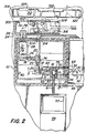
- Figure 2 is a top plan view of the system apparatus with a section taken below the roof or other covering.
- Figure 3 is a vertical sectional view of the primary and secondary chambers taken along the lines 3-3 in Figure 2.
- Figure 4 is a longitudinal sectional view of the CO 2 laser used with the present invention.
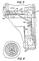
- Figure 5 is a sectional view of the system apparatus taken along lines 5-5 in Figure 3 showing the primary stack and one of the electrostatic precipitators used with the present invention.
- Figure 6 is a sectional view of the precipitator shown in Figure 5 taken along the lines 6-6.
- Figures 7A and 7B are longitudinal sectional views of a precipitator used with the system apparatus.
- Figure 8 is a sectional view of the precipitator shown in Figures 7A and 7B taken along the lines 8-8.
- Figures 9 is a perspective view of the water pool used as part of the effluvia transformation section of the system apparatus.
- Figure 1 schematically illustrates the system apparatus for implementing the process for making solid waste material environmentally safe using heat.
- the overall structure is shown in more detail in Figures 2 and 3.
- the masonry structure 10 houses the major components of the apparatus including the reaction chamber 16 in which the solid waste material is transformed to slag.
- Masonry structure 10 preferably is made of steel reinforced concrete.
- Temperature sensors 12 are positioned within the structure 10 to monitor the heat absorbed by the masonry. Such temperature sensors are connected to appropriate control and safety systems (not shown) for monitoring the temperatures within the walls to prevent crumbling and other adverse effects of heat on the masonry.
- the interior of each of the reaction chambers is covered with Francet ® or a similar heat resistant ceramic material. Heat exchangers (partly shown) surround the primary reaction chamber 16. Heat exchangers to provide sufficient cooling may be used as needed.
- the inner confinement structure 14 Positioned within the masonry structure 10 is an inner confinement structure 14 made of refractory brick.
- the inner confinement structure 14 provides the principal means for housing the reaction chamber 16 and second chamber 18, the primary and secondary stacks (or flues) 20 and 22, the precipitator 25, and the heat exchangers for cooling the gaseous and particulate effluvia of the process. More particularly, located within the inner confinement chamber 14 is the primary reaction chamber 16, the second chamber 18, the primary stack or flue 20, the secondary stack or flue 22, electrostatic precipitator 25, heat exchanger 26, and third chamber 28. The operation and functional interrelationship of each of the foregoing elements is explained hereinafter.
- a carbon dioxide (CO 2 ) laser 30 Located outside of the structure 10 is a carbon dioxide (CO 2 ) laser 30 whose optical axis 32 passes through the primary reaction chamber 16 to provide energy for initiating the heating process used to transform the solid waste material.
- the coherent radiation generated by the laser 30 passes along optical axis 32 through apertures 34 and 48 in the masonry structure 10 and confinement wall 14, respectively.
- Aperture 34 is controlled by a light valve 36.
- the optical axis 32 passes through apertures 34, 48 in the walls of reaction chamber 16 to the point of excitation 38 therein.
- the optical axis 32 is preferably pitched at an axis of from 5° to 10° from the horizontal.
- the optical axis 32 is aligned with the optical axis of the helium neon laser 40.
- Laser 40 is used to properly align the laser 30 by directing visible coherent radiation along the optical axis 32 through the point of excitation 38.
- a visible light laser, such as laser 40, is required because the radiation emitted by a CO 2 laser is not visible.
- the optical path 32 Due to the length of the optical path 32, it is necessary to provide a means for aligning the coherent radiation emitted by laser 30. This is accomplished using the helium-neon laser 40 as an auto collomator.
- the auto collomator guides adjustment of the optical axis 32, left, right, up or down. It also adjusts its azimuth.
- an Accu-ray 1007 available from Phoenix Environmental Ltd., the assignee of this invention may be used as the auto collomator.
- other optical means for aligning the radiation emitted by CO 2 laser 30 along an optical axis 32 may be used as desired.
- the principal purpose of the present invention is to provide an apparatus and process for transforming solid waste materials, especially fly ash, to a slag or ceramic-like solid material and a gaseous effluent.
- the gaseous effluent is supplementally processed to remove harmful particulates.
- the effluent is also processed to convert or neutralize other constituents to make it safe for release into the atmosphere.
- the present invention finds particular utility in the use of coherent radiation to initiate a high temperature process (1093-2186°C) (2,000°F to 4,000°F) for transforming solid waste materials which cannot be reduced by conventional combustion, such as fly ash or waste materials which cannot be safely burned in a conventional manner such as medical waste.
- Fly ash is a by-product of conventional combustion processes such as municipal incineration. As such, it will no longer readily burn in a conventional sense, that is by oxidation. It is therefore necessary to provide high temperatures in order to separate the ash into its constituents for removal of undesirable constituents. It is also desirable to convert the ash into a crystal-like material (herein also called slag). This effectively locks in or binds any remaining undesirable constituents to prevent them from leeching or otherwise entering the environment when the ceramic-like product of this invention is stored at an outdoor disposal site or put to useful purpose.
- slag crystal-like material
- the solid product resulting from the process described herein is called a slag.
- the product is not the slag which is a by-product of steel making. This term is chosen simply to characterize the products' hard, crystal-like physical appearance.
- the slag's actual chemical make-up is determined by chemical and physical analysis and depends on the solid waste material.
- Transformation of fly ash requires high temperatures to separate the constituent materials. Such temperatures are generated by combining the solid waste with combustible materials such as combustible waste materials, coal or wood chips, and oxygen.
- the combustible materials act as a fuel to provide heat at a high temperature for effecting the desired transformation of the solid waste materials.
- Another feature of this invention is the use of continuously fed particulates to create an effective volume of material.
- Laser 30, as more particularly shown in Figure 4, is mounted between aluminum I-beams 106, 108.
- I beam 108 is rigidly fixed to a granite slab, not shown.
- Laser 30 is preferably a 250 watt/cw carbon dioxide (CO 2 ) laser.
- CO 2 carbon dioxide
- Such lasers are available in the open market and any appropriate brand of laser may be selected for use with the present process.
- the laser used with the present invention is constructed by the inventor and is of the type illustrated in Figure 4.
- Aperture 34 is a 4" diameter gate valve angled approximately 20' from the axis of the laser to deflect the laser beam when the valve is closed, otherwise the laser would deflect back on itself.
- Aperture 34 is controlled by light valve 36, which functions to stop the laser beam and deflect the power at an angle.
- the aperture 34 (and all other apertures in the optical axis 32) is precisely aligned with the optical axis so as to permit entrance of the radiation through structure 10 and into the confinement chamber 14 (through aperture 48) while at the same time minimizing the escape of effluents.
- the coherent radiation is collomated.
- Heat exchanger 46 is connected to a reservoir of cooled liquid (e.g. water) for maintaining the light valve 36 and chamber wall at proper operating temperatures.
- cooled liquid e.g. water
- the coherent radiation also passes through an opening into primary reaction chamber 16 and through the point of excitation 38.
- Solid waste and excitation material is fed from hopper 50 into the primary reaction chamber through gate valve 54 controlled by actuator 55.
- the feed material is conveyed by conveyor 61 into hopper 50 from tipping bay 53 at the end of loading ramp 59.
- the feed material falls through tube 56 where it may be partially preheated.
- the combined solid waste and excitation material to be treated according to the process and apparatus of the present invention flows into the primary chamber 16 to the area encompassing the point of excitation 38. See Figure 3.
- Reaction chamber 16 is divided into a primary reaction core 77 and a primary reservoir 79.
- Reaction chamber 16 is 24,8 cm x 38,1 cm (9.75" x 15") in width and length.
- Initial excitation of the solid waste and excitation material takes place in core 77.
- the slag thus formed overflows into reservoir 79.
- the apparatus also includes chamber 18. This chamber is used to rapidly cool the effluvia flowing from reaction chamber 16 through inclined tube 64.
- the interior of both chambers 16 and 18 is coated with a hard, heat resistant material such as refractory brick or ceramic lining.
- the excitation material and the solid waste is raised to temperatures exceeding 1093°C (2,000°F) (e.g. 1631°C (3,000°F) or above).
- the excitation material mixed with the solid waste material is held in hopper 50 and then fed directly into reaction chamber 16.
- the preferred mixture is 50% solid waste and 50% excitation material by weight although other mixtures may be used if they does not adversely effect the quality of the effluvia discharged into the atmosphere.
- the principal reaction takes place in chamber 16 where, in the presence of oxygen only, the temperature of the solid waste material (and the excitation material) is raised to temperatures high enough to cause the solid waste to liquify and fuse. Also an effluvia of gases and particulates is formed.
- the effluvia flows up the tube 64 into the second chamber 18.
- the effluvia also flows through water cooled exhaust tube 65 to chamber 20.
- the major constituent of solid waste forms a molten, slag-like material.
- the molten slag fills the reaction core 77 and flows into the primary reservoir 79 until it too is filled.
- the entire reservoir 77, 79 fills until slag flows out through exit tube 66 to lava receiving tube 42.
- Slag flows through tube 42 into a receiving container 43 which, when filled, transports the slag to another location.
- the transformation process is initiated by placing a mixture of excitation material and waste material (e.g. coal and steel waste as previously described) in a small ladle 87 positioned at the excitation point 38.
- the excitation point 38 may be 10'16 to 12'7 cm (4 to 5 inches) above the floor of the reaction chamber 16.
- the starting mixture is simply piled on the floor of chamber 16 and the laser beam from laser 30 directed at it.
- the starting mixture may be 4'53 - 6'80 kg (10 to 15 lbs.) of coal and an equal amount of steel chips.
- the solid waste could also be "rebar" which is reinforced concrete rubble. This material is heated by the coherent radiation to near starting temperatures.
- Oxygen is also introduced once the starting mixture has reached the requisite temperature.
- oxygen from a source 68 is piped through 6 lances 70 into the reaction chamber 16 at the rate of 56'640 m 3 (2,000 ft 3 ) per hour.
- Lances 70 are arranged around the periphery of chamber 16 so as to introduce the oxygen at a chord angle to the vertical axis of the chamber.
- the oxygen swirls in a vortex within the chamber. The movement of the oxygen enhances the heating process.
- a feature of the present invention is the use of particulate waste material to start and maintain the process.
- the initial pool of molten material in itself is not commercially capable of handling volumes of waste. This small reaction is accelerated, with oxygen and previously described waste, to a large viable pool of high temperature liquid which is capable of handling commercial volumes of waste. It has been found that although it is possible to reach desired temperatures by directing the coherent radiation into a solid block of waste material, the pool of molten material is too small to be effective.
- the pool can be excited to fill the base of reaction chamber 16. This expanded pool engulfs the waste material and permits transformation thereof at commercially practicable rates.
- the laser 30 is operated at approximately 150 watts per cm (continuous wave (cw)) to excite the starting material to operating temperatures above 1093°C (2,000°F).
- Laser 30 is turned off after 3 to 20 seconds which is when the starter material reaches a liquid state at the point of impingement by the laser.
- Oxygen is introduced into chamber 16 through the lances 70. After several seconds, the reaction becomes self-sustaining and the laser may be shut down at this time.
- a gaseous and particulate effluvia is a principal product of heating the waste material.
- This gas includes products of combustion and inorganics.
- the effluvia flows up the tube 65 to the second chamber 18.
- the effluvia rapidly drops in temperature as it leaves reaction chamber 16 and flows through chamber 18 (approximately 1297°C (2,400°F) as it leaves chamber 16 to 649°C (1,200°F) to 760°C (1,400°F) as it exits chamber 18).
- This drop in temperature within 3 feet and in about 2 seconds causes the particulates to drop out. It has also been found that the initial heating at above 1093°C (2,000°F) destroys the organic compounds.
- the effluvia passes from the secondary reaction chamber 18 into the primary stack 20.
- the effluvia passes up the primary stack 20 and through the electrostatic precipitator 25. See Figure 5.
- Precipitator 25 is cooled by heat exchanger 74.
- Heat exchanger 26 comprises a Pyrex ® borosilicate glass tube with both an external heat exchanger 76 and an internal heat exchanger 78. See Figure 6. Both heat exchangers are liquid cooled.
- the heat exchanger 26 reduces the temperature of the effluvia flowing through it from approximately 1093°C (1,000°F) to 260°C (500°F).
- the cooled effluvia flows into the cooling chamber 28 where it is further reduced in temperature to between 37,8 - 93°C (100 and 200°F).
- Chamber 28 is a refractory walled chamber lined with ceramic. It includes a heat exchanger 260 for further cooling the effluvia.
- FIGs 7A, 7B and 8 illustrate the three electrostatic precipitators 24, 24' and 25 used with the process.
- the precipitators 24 and 24' are identical and differ from precipitator 25 only in that precipitator 25 does not include the gate valve 100 hereinafter described.
- each precipitator is housed within a protective refractory or metallic shell 82 within which is mounted a borosilicate glass (Pyrex) tube 84 held in place by bushings 86 and 88.
- Tube 84 is 121'9 cm (4 feet) in length, has an inside diameter of 17,78 cm (7"), and a wall thickness of 4,76 mm 3/16".
- the entire electrostatic precipitator is approximately 111'76 cm (44 inches) in length.
- One end of the tubes 82, 84 is closed by the plate 90 provided with a central aperture 102 through which the effluent is drawn.
- the aperture also provides for the admission of coherent radiation from a helium/neon laser for the purpose hereinafter described.
- Mounted at the entrance end of the precipitators 24, 24' is a heat exchanger 92.
- Each precipitator includes an elongated brass electrode 94 mounted above an opposing elongated brass electrode 96 which supports 200 pin resistors 98 mounted in four rows of 50 equally spaced pin resistors along its length.
- Each of the pin resistors includes a wire pin 99 projecting from a resistive material 101.
- Each pin resistor is 1,000 ohms and rated at 5 watts.
- Four rows of 50 pin resistors are provided as illustrated in Figures 7 and 8. The distal end of each pin resistor is spaced approximately 2'54 cm (1 inch) from the opposing surface of the brass electrode 94.
- Each of the pin resistors is electrically connected to the electrode 96 by a silver solder.
- End plates 90 and 91 which preferably are made of a ceramic, diaelectric material.
- End plates 90, 91 include apertures 102, 104, respectively, through which effluent is drawn into and out of the precipitators. Also coherent radiation from a helium neon laser may pass through the apertures.
- Electrode 94 and 96 are connected to a source of high voltage direct current. Electrode 94 is connected to the negative terminal and electrode 96 is connected to the positive terminal.
- a source of high voltage direct current For example, such source may be 15,000 volts. When the precipitators are operating, there will be a current flow between electrodes of between 5 to 50 milliamps.
- the effluent is drawn through the precipitator at a rate of approximately 2,944 m 3 (105 cubic feet) per minute (measured at the carbon filter 310) although each precipitator will function less efficiently at higher flow rates.
- the minimum flow rate for each precipitator is approximately 0,566 m 3 (20 ft 3 ) per minute.
- the precipitators 24, 25 expose a large cross section of the electrodes to the gas and, therefore, operate efficiently to remove any ionized particulates remaining in the effluent.
- Optional control over the flow of the gas through the precipitators 24, 24' may be provided by an electro neumatic gate valve 100 which includes a sensor for sensing the presence of light provided by a helium neon laser.
- a helium neon laser (not shown) is mounted with appropriate optics to direct coherent radiation through the apertures 102 and 104 in end plates 90 and 91.
- the gate valves 100 are not necessary and may be omitted.
- the sensor In operation, when the sensor detects the presence of the coherent radiation, this is an indication that there is no effluvia present. If however the gas is present, there will be sufficient reduction of the light intensity by the particulate material to scatter the radiation. This is sensed by the sensor indicating the operating status of precipitators.
- the electrostatic precipitator operates by creating an electrostatic field between the brass electrode 94 and the pin resistors 98. Particulates entrapped within the gas are attracted to the pin resistors and thus removed from the effluent. Cleanout petcocks 23 are provided.
- the electrostatic precipitators 24 and 24' are mounted in the wall of chamber 28; that is, they extend through walls 14 and 10 into the chamber 300.
- Precipitators 24, 24' may be operated singlely or in parallel as desired.
- the CO 2 laser 30 is illustrated in Figures 4 and 5. As shown, the laser is mounted on I-beams 106 and 108. The I-beam 108 is fixed to a granite slab (not shown). The brass high voltage electrodes 110 and 112 support the gas tube 114 which in turn is covered by a glass cooling jacket 116. The electrodes 110 and 112 are mounted between ceramic insulators 118 and fixed to the I-beams 106, 108 by nylon screws 120. The electrodes 110 and 112 are provided with gas fittings 121 and 122 for connection to a source of carbon dioxide and pumping equipment. The ports 124 and 126 through the electrodes 110 and 112 are closed by zinc selenide windows 128, 130.
- High reflectivity mirrors 132 and 134 are mounted at opposite ends of the laser 30.
- the mirrors are mounted on micro-adjustable precision gimbal mounts for proper adjustment.
- Mirror 132 is fully reflective whereas mirror 134 is 85% reflective.
- the output mirror 134 is zinc selenide.
- the mirror 132 is gold or platinum.
- a phosphor screen may be selectively inserted in the port 126 to align the front mirror in laser 30.
- the precipitators 24 and 24' extend through the walls 14 and 10 into the chamber 300 within which is provided one or more vacuum pumps 302.
- the vacuum pump 302 is designed to create a vacuum which pulls the effluvia through the entire system. In operation, the vacuum pump 302 should draw the effluvia through the system at an overall rate of approximately 8,50 - 14,16 m 3 (300-500 cubic feet) per minute although other rates may be desirable in some instances.
- the effluvia is pushed by the vacuum pump 302 through pipe 306 into a pool of water 304 located below the chamber 300.
- the effluvia exits from hole in the lower surface of pipe 306. See Figure 9.
- the effluvia next flows through a pipe 305 and pump 307 into the chamber 308.
- the effluvia flows through the carbon filter 310 and pipe 311 into the wind tunnel 312.
- Three filters 310 are used at a total capacity of 11,33 - 16,99 m 3 (400-600 ft 3 )/minute.
- the chamber 308 also includes a dehumidifier 314 and a compressor 316.
- the dehumidifier 314 largely used in warm weather, serves to remove moisture from the effluvia.
- the compressor 316 is used to draw gases from chamber 308.
- the overall flow rate through the compressor is 8,50 - 16,99 m 3 (300 to 600 ft 3 ) per hour at 875 kPa (125 lbs. per square inch).
- the wind tunnel may includes emissions testing apparatus.
- the carbon filter 310 is used to filter substantially all of the remaining particulate matter from the effluvia which then flows into the wind tunnel 312.
- the purpose of the wind tunnel 312 is to dilute the effluent, which now consists essentially of carbon dioxide (CO 2 ), oxygen (O 2 ) and water for exhaust into the atmosphere.
- the wind tunnel 312 includes a fan 318 which draws air into wind tunnel through the heat exchanger 320.
- the wind tunnel 312 is an elongated chamber which preferably is set at an approximately 45° angle to the horizontal with the fan 318 at the higher elevation.
- the wind tunnel 312 is lined with ceramic tile.
- the horizontal wind tunnel 312 gives easy access for maintenance; allows for a draw or negative pressure throughout the plant; provides easy access for emissions monitoring; and allows for the use of an argon laser for opacity analysis and laser spectrum analysis.
- the wind tunnel 312 includes a carbon filter 322 for removing particulate matter from the air prior to mixing the air with the effluent.
- effluent is mixed with air and then exhausted by the fan 316 into the atmosphere.
- the wind tunnel exhausts mixed air and air quality effluvia at a rate of 141,6 m 3 (5,000 ft 3 ) per minute.
- An air quality monitor 324 is mounted on the wall of the wind tunnel 312 adjacent to the fan.
- FIG. 3 illustrates the manner in which the slag is treated as it flows from the primary reaction chamber 16.
- the liquid slag stream flows down exit tube 66.
- the slag begins to harden.
- the liquid flows through a stream of compressed air directed into the tube 66 through the pipe 332.
- the compressed air causes the liquid stream to separate into small globules which ultimately harden into individual pebbles as they are cooled by the heat exchanger 330. These slag pebbles then flow through tube 42 into the collection container 43.
- the liquid stream next flows through the tube 328 which is surrounded by the heat exchanger 330.
- the lava is cooled by the heat exchanger 330.
- the process of reducing solid waste material to a more readily disposable slag is commenced by placing a mixture of solid waste (e.g. steel waste) and excitation material in reaction chamber 16.
- a mixture of solid waste e.g. steel waste
- excitation material e.g. steel waste
- the starting material may also be 40% rebar, 30% wood chips and 30% coal by weight, for example.
- Coherent radiation at about 150 watts/cm 2 cw is directed at the bed which is positioned at the excitation point 38.
- the hopper 50 is filled with mixed metal chips, coal, glass and wood chips in readiness for feeding into the primary chamber 16 through the tube 56.
- the hopper 50 may be continuously filled from the tipping bay 53. Enough mixed steel chips and coal should be available to maintain the process once initiated. Present calculations indicate that the process should reduce the solid waste steel chips at a rate of approximately 4'53 kg (10 lbs) per minute.
- Rice coal is oval in shape 19,05 mm (3/4") along its major axis, 12,7 mm (1/2") along its minor axis, and 6,35 mm (1/4") thick). Rice coal is readily available. However, other particle sizes (both smaller and larger) may be used. Generally larger particle sizes may be used for reaction chambers larger than the chamber 16 described herein.
- the coherent radiation from laser 30 impinges upon the starter material until it reaches a temperature or 1353°C (2,500°F) or greater. It has been found that the use of particulates as a starter material allows the heating process to commence rapidly within primary reaction chamber 16.
- oxygen is introduced through the 6 lances 70 located near the bottom of the chamber 16.
- the oxygen is introduced at approximately 56,64 m 3 (2,000 ft 3 )/hr. (9,43 m 3 (333 ft 3 )/hr. per lance).
- a range of 25,49 - 33,98 m 3 (900 to 1,200 ft 3 )/hr may be used depending upon the effect on air quality in the wind tunnel.
- the oxygen from lances 70 is emitted into the primary reaction chamber 16 at an angle so that the gases within that chamber are forced to swirl within the chamber, which helps distribute the heat throughout the chamber.
- the temperature of the starting material rises within chamber 16 to over 1631°C (3,000°F). This takes about 5 to 45 minutes until the starting mixture fuses to puddles of liquid.
- the gate valve 54 is opened and the particulate solid waste and excitation material such as coal mix is continuously fed into the primary reaction chamber.
- the solid waste and excitation material is injected into chamber starting at a rate 4,53 - 9,06 N (1 to 2 lbs.)/min.
- the material is fed at this rate until a 228,6 mm (9") diameter liquid bath about 12,7 mm (1/2") deep forms in the bottom of chamber 16.
- the feed rate is then increased to 3 lbs./min. until the bath grows to a depth of 5'08 cm (2 inches).
- the feed rate is then increased to 14,949 kg (33 lbs.)/min., which is the typical operating rate for this particular system.
- the energy for fusing the solid waste (steel chips in this example) is supplied by the particulate coal; i.e. 87921'3 watts (3,000,000 btu/hr).
- the compressor 316 recirculates effluvia into the chamber 16 at a rate of 11,33 - 16,99 m 3 (400-600 ft 3 )/hr.
- the feed rates and composition of the feed mix will be adjusted empirically depending upon the solid waste material being combusted. Specifically, the parameters are adjusted to reach chamber temperatures in excess of 1993°C (2,000°F), that is in the range of 1093 - 1631°C (2,000-3,000°F).
- the slag Once the slag has filled chamber 16 as described above, it flows down tube 66.
- the slag can be converted into a pebble-like form by a blast of compressed air from tube 332 or can be poured into a mold.
- the coherent radiation from laser 326 if used, causes them to anneal and thereby better lock in any remaining metals or other constituents.
- the slag then falls through tube 328 surrounded by heat exchanger 330 which cools it further.
- the hardened slag flows through tube 42 into the container 43. When container 43 is filled, it may be moved outdoors to allow the slag to reach ambient temperatures and thereafter be transferred to another site.
- the hot gaseous effluvia from the heating process flows up tube 64 into the chamber 18.
- the effluvia flowing into the secondary chamber 18 includes products of combustion and inorganics.
- Chamber 18 greatly enhances the total output of the system by providing an efficient means for treating the effluvia. This allows better control of the effluvia for ultimately exhausting it into the atmosphere. Specifically, the effluvia is rapidly cooled as it passes from chamber 16 (1260°C - 1315'5°C (2,300°F-2,400°F) at the entrance to tube 61) into and out of chamber 18. This cooling removes most of the particulate matter as the effluvia temperature decreases by 538°C - 815'5°C (1,000°F to 1,500°F) causing the particulate to precipitate in chamber 18. Residence time in chamber 18 is about 2 seconds.
- the effluvia is drawn from the secondary chamber 18 through the primary stack 20 where it is further cooled.
- the heated effluvia then passes through precipitator 25.
- the precipitator 25 ionizes remaining the particulate matter in the effluvia, such as the heavy metals and arsenic, and causes them to collect on or about the electrodes.
- the precipitator 25 includes petcocks 23 which permit the collected particles to be removed.
- the effluvia flows up the secondary stack 22 and through the heat exchanger 26 into the cooling chamber 28 at approximately 260°C (500°F). Within the cooling chamber 28, the heat exchanger 260 reduces the temperature of the effluvia to between 38 + 93°C (100 and 200°F).
- the effluvia then flows through one or both of the precipitators 24 and 24' where additional remaining particulate matter is substantially electrostatically removed from the effluvia.
- the vacuum pump 302 forces the effluvia to flow from chamber 300 through a pipe below the surface of pool 304 which is filled with water.
- the effluent is bubbled up from pipe 306, to pipe 305 into 3 carbon filters 310 (combined capacity 8,49 - 14,16 m 3 (300-500 ft 3 /min.)) and then passes into the wind tunnel 312. Pump 307 assists in this process.
- the fan 316 mixes the effluent with atmospheric air. At this point the effluent consists of dilute carbon dioxide and water vapor. This effluent is freely exhausted into the atmosphere at 15,6 - 21,1°C (60°F-70°F).
- the aluminum and steel chips are industrial waste such as aluminum stampings and cold rolled steel shavings. Waste glass simulates the presence of silica. Wood chips provide additional fuel. And the miscellaneous materials include cutting oils and debris.
- the burn lasted from 11:20 A.M. to 1:05 P.M. and was monitored every 5 minutes.
- the process has been described for fusing steel waste and coal as the excitation material.
- the process is also applicable to incinerator ash and rebar as a solid waste.
Landscapes
- Engineering & Computer Science (AREA)
- Chemical & Material Sciences (AREA)
- Physics & Mathematics (AREA)
- Mechanical Engineering (AREA)
- General Engineering & Computer Science (AREA)
- Organic Chemistry (AREA)
- Plasma & Fusion (AREA)
- Materials Engineering (AREA)
- Optics & Photonics (AREA)
- Electromagnetism (AREA)
- Health & Medical Sciences (AREA)
- General Health & Medical Sciences (AREA)
- Toxicology (AREA)
- Chemical Kinetics & Catalysis (AREA)
- Processing Of Solid Wastes (AREA)
- Gasification And Melting Of Waste (AREA)
Claims (25)
- Verfahren zur Entfernung schädlicher Bestandteile aus Feststoffabfall, welches folgende Schritte umfaßt: kontinuierliches Zuführen einer Partikelmischung aus Feststoffabfall und eines brennbaren Anregungsmaterials zur Lieferung von Wärmeenergie in eine Reaktionskammer (16), wobei das Verfahren gekennzeichnet ist durch das Einleiten von nur Sauerstoff in die Kammer (16), um darin eine Sauerstoffatmosphäre zu erzeugen, das Umsetzen der Mischung in der Kammer (16) in der Sauerstoffatmosphäre, bis der Feststoffabfall eine geschmolzene Schlacke wird und Effluvia entstehen, die einen gasförmigen Ablauf und einen partikelförmigen Ablauf umfassen, wobei die Temperatur in der Kammer (16) über der geschmolzenen Schlacke hoch genug ist, um im wesentlichen alle schädlichen Bestandteile der Effluvia zu zerstören, die durch die Bildung der geschmolzenen Schlacke freigesetzt werden, und das Ableiten der Effluvia, die durch die Bildung der geschmolzenen Schlacke entstehen, aus der Reaktionskammer (16) und rasches Abkühlen der Effluvia, so daß der darin enthaltene partikelförmige Ablauf ausfällt.
- Verfahren zur Entfernung schädlicher Bestandteile aus Feststoffabfall nach Anspruch 1, welches ferner folgenden Schritt umfaßt: das Ableiten überschüssiger geschmolzener Schlacke aus der Reaktionskammer (16).
- Verfahren zur Entfernung schädlicher Bestandteile aus Feststoffabfall nach Anspruch 1, welches ferner folgende Schritte umfaßt: das Behandeln der Effluvia zur Entfernung von im wesentlichen allen übrigen Partikeln und schädlichen Bestandteilen des gasförmigen Ablaufs, um eine annehmbare Umweltqualität nach dem Kühlen des Ablaufs zu erhalten, und das Freisetzen des behandelten gasförmigen Ablaufs in die Atmosphäre.
- Verfahren zur Entfernung schädlicher Bestandteile aus Feststoffabfall nach Anspruch 1, wobei der Feststoffabfall nicht brennbar ist.
- Verfahren nach Anspruch 1, wobei der Feststoffabfall Asche eines Müllverbrennungsofens ist.
- Verfahren nach Anspruch 1, wobei der Feststoffabfall Flugasche eines Müllverbrennungsofens ist.
- Verfahren nach Anspruch 1, wobei der Feststoffabfall Stahlabfall ist.
- Verfahren nach Anspruch 1, wobei der Feststoffabfall Betonrippenstahl ist.
- Verfahren nach Anspruch 1, wobei die Temperatur in der Reaktionskammer (16) über der geschmolzenen Schlacke mindestens 1093°C (2000°F) beträgt.
- Verfahren nach Anspruch 1, wobei die Temperatur in der Reaktionskammer (16) über der geschmolzenen Schlacke etwa 1093°C (2000°F) bis etwa 1631°C (3000°F) beträgt.
- Verfahren nach Anspruch 1, wobei die Effluvia, die durch die Bildung der Schlacke erzeugt werden, aus der Reaktionskammer (16) in eine zweite Kammer (18) geleitet werden und die Effluvia in der zweiten Kammer (18) rasch abgekühlt werden.
- Verfahren nach Anspruch 1, wobei die Effluvia in einer zweiten Kammer (18) durch Verringerung ihrer Temperatur um mindestens 538°C (1000°F) abgekühlt werden.
- Verfahren nach Anspruch 1, wobei die Effluvia in einer zweiten Kammer (18) durch Verringerung ihrer Temperatur um mindestens 538°C (1000°F) in weniger als 2 Sekunden abgekühlt werden.
- Verfahren nach Anspruch 3, wobei der Schritt zur Behandlung der Effluvia folgendes enthält: das Hindurchleiten der Effluvia durch ein Wasserbad (304) zur Neutralisierung der Effluvia, das Hindurchleiten der Effluvia durch einen Filter (310) zur Entfernung von Partikeln, und das Mischen des gasförmigen Ablaufs mit atmosphärischer Luft vor dem Ausstoßen in die Atmosphäre.
- Verfahren nach Anspruch 14, wobei der Schritt zur Behandlung der Effluvia deren Hindurchleiten durch einen elektrostatischen Ausfällapparat (24, 24', 25) zur Entfernung metallischer Partikel umfaßt.
- Verfahren nach Anspruch 1, wobei der Schritt zur Behandlung der Effluvia deren Hindurchleiten durch einen elektrostatischen Ausfällapparat (24, 24', 25) zur Entfernung von Partikeln umfaßt.
- Verfahren nach Anspruch 1, wobei die Reaktion der Mischung entzündet wird, indem kohärente Strahlung auf eine Masse der Ausgangsmischung gerichtet wird, die sich in der Reaktionskammer (16) befindet.
- Verfahren nach Anspruch 1, wobei die schädlichen Bestandteile in den Effluvia, die über der Schlacke zerstört werden, organische Materialien enthalten, die aus dem Feststoffabfall freigesetzt werden.
- Vorrichtung zur Entfernung schädlicher Bestandteile aus Feststoffabfall, umfassend: eine Reaktionskammer (16), Mittel (54) zum kontinuierlichen Zuführen einer Partikelmischung des Feststoffabfall und eines brennbaren Anregungsmaterials als Quelle von Wärmeenergie in die Reaktionskammer (16), wobei die Vorrichtung gekennzeichnet ist durch ein Lanzenmittel (70) zum Einleiten von nur Sauerstoff von einer Sauerstoffquelle (68) in die Reaktionskammer (16), um darin eine Sauerstoffatmosphäre zu erzeugen und die Sauerstoffatmosphäre in der Reaktionskammer (16) aufrechtzuerhalten, Mittel (30, 32 40) zum Erwärmen der Reaktionskammer (16), um die Mischung in der Kammer (16) in Gegenwart der Sauerstoffatmosphäre umzusetzen, bis der Feststoffabfall eine geschmolzene Schlacke wird und Effluvia entstehen, die einen gasförmigen Ablauf und einen partikelförmigen Ablauf umfassen, wobei die Temperatur in der Kammer (16) über dem Bad der geschmolzenen Schlacke hoch genug ist, um im wesentlichen alle schädlichen Bestandteile der Effluvia zu zerstören, die durch die Bildung der geschmolzenen Schlacke erzeugt werden, Mittel (66) zum Ableiten überschüssiger geschmolzener Schlacke aus der Reaktionskammer (16), Mittel (65) zum Ableiten der Effluvia, die durch die Bildung der geschmolzenen Schlacke entstehen, aus der Reaktionskammer (16) in eine zweite Kammer (18), wobei die zweite Kammer (18) zum raschen Abkühlen der Effluvia ausgebildet ist, so daß darin enthaltenes partikelförmiges Material ausgefällt wird, Mittel zum Behandeln der Effluvia, um im wesentlichen alle verbleibenden Partikel und schädlichen Bestandteile zu entfernen und eine annehmbare Umweltqualität zu erzielen, und Mittel (316) zum Freisetzen des behandelten gasförmigen Ablaufs in die Atmosphäre.
- Vorrichtung zur Entfernung schädlicher Bestandteile aus Feststoffabfall nach Anspruch 19, wobei das Mittel zum Behandeln des Ablaufs mindestens einen elektrostatischen Ausfällapparat (24, 25) umfaßt.
- Vorrichtung zur Entfernung schädlicher Bestandteile aus Feststoffabfall nach Anspruch 19, wobei das Mittel zum Behandeln des Ablaufs einen elektrostatischen Ausfällapparat (24, 25), ein Filtermittel (310) und ein Flüssigkeitsbad (304) und Mittel (302) umfaßt, die ein Hindurchgehen der Effluvia durch das Flüssigkeitsbad (304) bewirken.
- Vorrichtung zur Entfernung schädlicher Bestandteile aus Feststoffabfall nach Anspruch 19, wobei die Vorrichtung einen Windkanal (312) zum Mischen des behandelten gasförmigen Ablaufs mit atmosphärischer Luft vor dessen Freisetzen in die Atmosphäre umfaßt.
- Vorrichtung zur Entfernung schädlicher Bestandteile aus Feststoffabfall nach Anspruch 20, wobei der elektrostatische Ausfällapparat (24, 25) eine längliche Röhre (84) und einen Satz länglicher Elektroden (94, 96) in der Röhre (84) umfaßt, wobei die Elektroden (94, 96) parallel zueinander und einander gegenüberliegend angeordnet sind und eine der Elektroden (96) einen Satz von Resistorstiften (98) enthält, die sich zu der gegenüberliegenden Elektrode (94) erstrecken.
- Verfahren zur Entfernung schädlicher Bestandteile aus Feststoffabfall, welches folgende Schritte umfaßt: das Zuführen von partikelförmigem Feststoffabfall in eine Reaktionskammer (16), das Erwärmen des Feststoffabfalls in der Reaktionskammer (16), wobei das Verfahren gekennzeichnet ist durch das Einleiten von nur Sauerstoff in die Kammer (16), um darin eine Sauerstoffatmosphäre zu erzeugen, das Umsetzen des Feststoffabfalls in der Kammer (16) in der Sauerstoffatmosphäre, so daß der Feststoffabfall eine geschmolzene Schlacke wird und Effluvia entstehen, die einen gasförmigen Ablauf und einen partikelförmigen Ablauf umfassen, wobei die Temperatur in der Kammer (16) über der geschmolzenen Schlacke hoch genug ist, um im wesentlichen alle schädlichen Bestandteile in den Effluvia zu zerstören, die durch die Bildung der geschmolzenen Schlacke freigesetzt werden, das Ableiten überschüssiger geschmolzener Schlacke aus der Reaktionskammer (16), das Ableiten der Effluvia, die durch die Bildung der geschmolzenen Schlacke entstehen, aus der Reaktionskammer (16) und rasches Abkühlen der Effluvia, so daß darin enthaltenes partikelförmiges Material ausfällt, das Weiterbehandeln der Effluvia zur Entfernung von im wesentlichen allen übrigen Partikeln und schädlichen Bestandteilen der Effluvia, um eine annehmbare Umweltqualität zu erzielen, und das Freisetzen des behandelten gasförmigen Ablaufs in die Atmosphäre.
- Verfahren nach Anspruch 24, wobei die schädlichen Bestandteile in den Effluvia, die erwärmt und über der Schlacke zerstört werden, organische Materialien enthalten, die aus dem Feststoffabfall freigesetzt werden.
Applications Claiming Priority (5)
| Application Number | Priority Date | Filing Date | Title |
|---|---|---|---|
| US07/410,560 US4960380A (en) | 1989-09-21 | 1989-09-21 | Method and apparatus for the reduction of solid waste material using coherent radiation |
| US07/533,653 US5065680A (en) | 1989-09-21 | 1990-06-04 | Method and apparatus for making solid waste material environmentally safe using heat |
| US533653 | 1990-06-04 | ||
| PCT/US1990/005243 WO1991004443A1 (en) | 1989-09-21 | 1990-09-14 | Method and apparatus for making solid waste material environmentally safe using heat |
| US410560 | 2003-04-09 |
Publications (4)
| Publication Number | Publication Date |
|---|---|
| EP0489867A1 EP0489867A1 (de) | 1992-06-17 |
| EP0489867A4 EP0489867A4 (en) | 1993-04-07 |
| EP0489867B1 true EP0489867B1 (de) | 1996-11-13 |
| EP0489867B2 EP0489867B2 (de) | 2005-08-17 |
Family
ID=27021048
Family Applications (1)
| Application Number | Title | Priority Date | Filing Date |
|---|---|---|---|
| EP90914582A Expired - Lifetime EP0489867B2 (de) | 1989-09-21 | 1990-09-14 | Verfahren und vorrichtung um durch anwendung von hitze feststoffabfall umweltunschädlich zu machen |
Country Status (6)
| Country | Link |
|---|---|
| US (1) | US5065680A (de) |
| EP (1) | EP0489867B2 (de) |
| AT (1) | ATE145274T1 (de) |
| DE (1) | DE69029139T2 (de) |
| PL (1) | PL286998A1 (de) |
| WO (1) | WO1991004443A1 (de) |
Families Citing this family (23)
| Publication number | Priority date | Publication date | Assignee | Title |
|---|---|---|---|---|
| US5976488A (en) * | 1992-07-02 | 1999-11-02 | Phoenix Environmental, Ltd. | Process of making a compound having a spinel structure |
| US5420394A (en) * | 1992-12-09 | 1995-05-30 | Eshleman; Roger D. | Casing and heater configuration in a material processing apparatus |
| US5338918A (en) * | 1992-12-09 | 1994-08-16 | Eshleman Roger D | Heat generator assembly in a material processing apparatus |
| US5353719A (en) * | 1992-12-09 | 1994-10-11 | Eshleman Roger D | Apparatus and method for controlled processing of materials |
| US5289787A (en) * | 1992-12-09 | 1994-03-01 | Eshleman Roger D | Multiple unit material processing apparatus |
| US5417170A (en) * | 1993-09-17 | 1995-05-23 | Eshleman; Roger D. | Sloped-bottom pyrolysis chamber and solid residue collection system in a material processing apparatus |
| US5428205A (en) * | 1993-09-17 | 1995-06-27 | Eshleman; Roger D. | Casing and heater configuration in a material processing apparatus |
| US5361709A (en) * | 1993-09-17 | 1994-11-08 | Eshleman Roger D | Material transport pusher mechanism in a material processing apparatus |
| US5323716A (en) * | 1993-09-17 | 1994-06-28 | Eshleman Roger D | Heater and tunnel arrangement in a material processing apparatus |
| WO1995014191A1 (en) * | 1993-11-19 | 1995-05-26 | Phoenix Environmental, Ltd. | System for converting solid waste material into environmentally safe products |
| US5534659A (en) * | 1994-04-18 | 1996-07-09 | Plasma Energy Applied Technology Incorporated | Apparatus and method for treating hazardous waste |
| US5648592A (en) * | 1994-05-03 | 1997-07-15 | Pierce; Charles L. | Method and apparatus for treating waste and for obtaining usable by-product |
| US5886316A (en) * | 1994-05-03 | 1999-03-23 | Consolidated Fusion Technologies, Inc. | Method and apparatus for treating waste and for obtaining usable by-product |
| US5611947A (en) * | 1994-09-07 | 1997-03-18 | Alliant Techsystems, Inc. | Induction steam plasma torch for generating a steam plasma for treating a feed slurry |
| EP0716153B1 (de) * | 1994-12-08 | 2001-03-07 | Daido Tokushuko Kabushiki Kaisha | Verfahren und Ofen zum Entsorgen von Stahlwerkabfällen sowie Betriebsverfahren für diesen Ofen |
| US5762009A (en) * | 1995-06-07 | 1998-06-09 | Alliant Techsystems, Inc. | Plasma energy recycle and conversion (PERC) reactor and process |
| GB2318786B (en) * | 1996-10-30 | 1999-09-01 | Univ Sheffield | Fly ash treatment |
| US20050070751A1 (en) * | 2003-09-27 | 2005-03-31 | Capote Jose A | Method and apparatus for treating liquid waste |
| US6971323B2 (en) | 2004-03-19 | 2005-12-06 | Peat International, Inc. | Method and apparatus for treating waste |
| US20060049091A1 (en) * | 2004-09-03 | 2006-03-09 | Cheetham Jeffrey K | Reactive adsorbent for heavy elements |
| US7832344B2 (en) * | 2006-02-28 | 2010-11-16 | Peat International, Inc. | Method and apparatus of treating waste |
| EP2247347A4 (de) * | 2008-02-08 | 2013-08-14 | Peat International Inc | Verfahren und vorrichtung zur behandlung von abfall |
| US8671855B2 (en) | 2009-07-06 | 2014-03-18 | Peat International, Inc. | Apparatus for treating waste |
Family Cites Families (75)
| Publication number | Priority date | Publication date | Assignee | Title |
|---|---|---|---|---|
| US1130212A (en) * | 1914-01-07 | 1915-03-02 | Semet Solvay Co | Art of removing tarry substances from gas. |
| US2800091A (en) * | 1952-02-06 | 1957-07-23 | Babcock & Wilcox Co | Cyclone furnace |
| US2979000A (en) * | 1954-02-16 | 1961-04-11 | Babcock & Wilcox Co | Cyclone furnace unit and method of operating the same |
| US2917011A (en) * | 1956-05-10 | 1959-12-15 | Kohlenscheidungs Gmbh | Apparatus and method for melting fly ash in a tangentially fired furnace chamber |
| US4702808A (en) * | 1957-06-27 | 1987-10-27 | Lemelson Jerome H | Chemical reaction apparatus and method |
| BE667169A (de) * | 1964-07-21 | |||
| CH437919A (de) * | 1966-05-06 | 1967-06-15 | G A Messen Jaschin Fa | Einrichtung zum Reinigen von Auspuffgas mittels Elektrofilter |
| US3656441A (en) * | 1970-10-26 | 1972-04-18 | Morse Boulger Inc | Incinerator |
| US4367130A (en) * | 1970-11-30 | 1983-01-04 | Lemelson Jerome H | Chemical reaction |
| US3722733A (en) * | 1971-05-17 | 1973-03-27 | R Neumann | Fire extinguisher cabinet |
| US3771468A (en) * | 1972-01-20 | 1973-11-13 | P Kelly | Waste disposal |
| US3780675A (en) * | 1972-04-18 | 1973-12-25 | Boardman Co | Plasma arc refuse disintegrator |
| US3832519A (en) * | 1972-08-11 | 1974-08-27 | Westinghouse Electric Corp | Arc heater with integral fluid and electrical ducting and quick disconnect facility |
| US3913499A (en) * | 1973-03-08 | 1975-10-21 | Koppers Co Inc | Refuse burner apparatus |
| US3834326A (en) * | 1973-04-26 | 1974-09-10 | Environmental Prod Inc | Low pollution incineration of solid waste |
| JPS50108769A (de) * | 1974-02-06 | 1975-08-27 | ||
| US3910207A (en) * | 1974-05-28 | 1975-10-07 | Berton G Altmann | Apparatus for pyrolytic decomposition of waste materials |
| US4012301A (en) * | 1975-07-28 | 1977-03-15 | Calspan Corporation | Method and apparatus for the initiation of chemical reactions |
| US4051791A (en) * | 1975-08-15 | 1977-10-04 | Wormser Engineering, Inc. | Coal burning arrangement |
| US4181504A (en) * | 1975-12-30 | 1980-01-01 | Technology Application Services Corp. | Method for the gasification of carbonaceous matter by plasma arc pyrolysis |
| US4038108A (en) * | 1976-05-10 | 1977-07-26 | Union Carbide Corporation | Method and apparatus for making an instantaneous thermochemical start |
| US4411695A (en) * | 1977-02-25 | 1983-10-25 | Apros Corporation | Metallic scrap decontamination process |
| US4167463A (en) * | 1978-04-12 | 1979-09-11 | The United States Of America As Represented By The Secretary Of The Army | Nitrogen fixation with a high energy laser |
| US4213404A (en) * | 1978-11-09 | 1980-07-22 | Energy Alternatives, Inc. | Solid refuse furnace |
| FR2443645A1 (fr) * | 1978-12-04 | 1980-07-04 | Air Liquide | Procede et installation de traitement de dechets industriels |
| JPS5595900A (en) * | 1979-01-12 | 1980-07-21 | Hitachi Ltd | Radioactive waste processing method |
| DE2918758A1 (de) * | 1979-05-09 | 1980-11-13 | Herko Pyrolyse Recycling | Vorrichtung und verfahren zur pyrolyse von abfallstoffen |
| US4266948A (en) * | 1980-01-04 | 1981-05-12 | Envirotech Corporation | Fiber-rejecting corona discharge electrode and a filtering system employing the discharge electrode |
| US4308807A (en) * | 1980-03-17 | 1982-01-05 | Stokes Samuel L | Apparatus for pyrolysis of municipal waste utilizing heat recovery |
| US4346661A (en) * | 1980-03-20 | 1982-08-31 | Osaka Gas Kabushiki Kaisha | Furnace for treating industrial wastes |
| US4291634A (en) * | 1980-05-29 | 1981-09-29 | Union Carbide Corporation | Solid refuse disposal apparatus |
| US4320709A (en) * | 1980-09-29 | 1982-03-23 | Pyro-Sciences, Inc. | Hazardous materials incineration system |
| US4384968A (en) * | 1980-11-17 | 1983-05-24 | Betz Laboratories, Inc. | Electrostatic precipitator efficiency enhancement |
| HU184389B (en) * | 1981-02-27 | 1984-08-28 | Villamos Ipari Kutato Intezet | Method and apparatus for destroying wastes by using of plasmatechnic |
| US4438705A (en) * | 1981-03-27 | 1984-03-27 | Basic J N Sen | Incinerator with two reburn stages, and, optionally, heat recovery |
| US4432344A (en) * | 1981-07-15 | 1984-02-21 | Focus Environmental Systems | Method and apparatus for solar destruction of toxic and hazardous materials |
| US4408985A (en) * | 1981-09-14 | 1983-10-11 | Anderson Mark A | Method of fixing hazardous substances in waste foundry sand |
| JPS5860113A (ja) * | 1981-10-05 | 1983-04-09 | Kubota Ltd | 廃棄物の溶融処理方法 |
| IL66144A (en) † | 1982-01-18 | 1985-06-30 | Skf Steel Eng Ab | Method and plant for conversion of waste material to stable final products |
| US4397823A (en) * | 1982-01-29 | 1983-08-09 | Chevron Research Company | Process and apparatus for removing a pollutant from a gas stream |
| US4479443A (en) * | 1982-03-08 | 1984-10-30 | Inge Faldt | Method and apparatus for thermal decomposition of stable compounds |
| US4724776A (en) * | 1982-08-03 | 1988-02-16 | Sam Foresto | Burning apparatus with means for heating and cleaning polluted products of combustion |
| EP0106258A3 (de) * | 1982-10-09 | 1985-05-15 | Heinz Dipl.-Ing. Hölter | Verfahren zur kontinuierlichen Nutzung von Abfall, vorzugsweise Müll und Klärschlamm |
| FR2541428A1 (fr) * | 1983-02-17 | 1984-08-24 | Commissariat Energie Atomique | Procede de combustion du bitume |
| US4447262A (en) * | 1983-05-16 | 1984-05-08 | Rockwell International Corporation | Destruction of halogen-containing materials |
| US4582004A (en) * | 1983-07-05 | 1986-04-15 | Westinghouse Electric Corp. | Electric arc heater process and apparatus for the decomposition of hazardous materials |
| US4539916A (en) * | 1983-08-11 | 1985-09-10 | Paoluccio John A | Apparatus for cleaning flue gases and other gases |
| US4685220A (en) * | 1983-09-02 | 1987-08-11 | American Toxic Disposal Partners | Method and apparatus for separating dioxin from fluidizable solids |
| IN161460B (de) * | 1983-11-14 | 1987-12-05 | Voest Alpine Ag | |
| CA1225441A (en) * | 1984-01-23 | 1987-08-11 | Edward S. Fox | Plasma pyrolysis waste destruction |
| US4552667A (en) * | 1984-06-25 | 1985-11-12 | Shultz Clifford G | Destruction of organic hazardous wastes |
| US4695447A (en) * | 1984-07-09 | 1987-09-22 | Detox International Corporation | Destruction of inorganic hazardous wastes |
| NO171473C (no) * | 1984-09-21 | 1993-03-17 | Skf Steel Eng Ab | Fremgangsmaate ved destruering av miljoefarlig avfall |
| US4615283A (en) * | 1984-09-26 | 1986-10-07 | Westinghouse Electric Corp. | Apparatus and method for disposal of hazardous waste material |
| US4599955A (en) * | 1984-10-24 | 1986-07-15 | Amax Inc. | Coal slagging burner for producing clean low-sulfur fuel gas |
| US4602574A (en) * | 1984-11-08 | 1986-07-29 | United States Steel Corporation | Destruction of toxic organic chemicals |
| US4574714A (en) * | 1984-11-08 | 1986-03-11 | United States Steel Corporation | Destruction of toxic chemicals |
| US4685404A (en) * | 1984-11-13 | 1987-08-11 | Trw Inc. | Slagging combustion system |
| US4688495A (en) * | 1984-12-13 | 1987-08-25 | In-Process Technology, Inc. | Hazardous waste reactor system |
| US4579067A (en) * | 1984-12-19 | 1986-04-01 | Ecolotec Research Inc. | Combustion reactor |
| DE3611429A1 (de) * | 1985-02-15 | 1986-11-06 | SKF Steel Engineering AB, Hofors | Verfahren zur abfallzersetzung |
| LU85980A1 (fr) † | 1985-06-28 | 1987-01-13 | Alpha Foundation | Procede et installation pour l'incineration de combustibiles |
| DE3532978C1 (de) * | 1985-09-16 | 1986-12-04 | Dr. Engelter & Nitsch Wirtschaftsberatung, 6000 Frankfurt | Elektrodenanordnung fuer Koronaentladungen |
| US4695448A (en) * | 1985-09-26 | 1987-09-22 | Grand Junction Reality Co., Inc. | Reduction and disposal of toxic waste |
| US4732091A (en) * | 1985-09-30 | 1988-03-22 | G.G.C., Inc. | Pyrolysis and combustion process and system |
| US4821653A (en) * | 1986-02-20 | 1989-04-18 | Jones Bradford H | Process and apparatus for fixing, encapsulating, stabilizing and detoxifying heavy metals and the like in metal-containing sludges, soils, ash and similar materials |
| US4793270A (en) * | 1986-12-24 | 1988-12-27 | University Of Waterloo | Incineration of waste materials |
| US4958578A (en) * | 1987-01-30 | 1990-09-25 | Phillips Petroleum Company | Drummed waste incineration |
| US4781171A (en) * | 1987-07-06 | 1988-11-01 | Indugas, Inc. | Gas fired particulate melting apparatus and method |
| DE3724563A1 (de) † | 1987-07-24 | 1989-02-02 | Kernforschungsanlage Juelich | Verfahren zur thermischen behandlung von abfaellen sowie vorrichtung zur durchfuehrung dieses verfahrens |
| US4873930A (en) * | 1987-07-30 | 1989-10-17 | Trw Inc. | Sulfur removal by sorbent injection in secondary combustion zones |
| DE3735061A1 (de) † | 1987-10-16 | 1989-04-27 | Fischer Reinhard | Verfahren zur beseitigung von abfaellen durch verbrennen mit sauerstoff |
| US4759300A (en) * | 1987-10-22 | 1988-07-26 | Balboa Pacific Corporation | Method and apparatus for the pyrolysis of waste products |
| US4848995A (en) * | 1988-02-05 | 1989-07-18 | Shell Oil Company | Removal of sulfur oxides from flue gas |
| US4909160A (en) * | 1988-10-24 | 1990-03-20 | Eta Engineering, Inc. | Temperature-controlled exhaust particulate collection system for high temperature material processing facility |
-
1990
- 1990-06-04 US US07/533,653 patent/US5065680A/en not_active Expired - Lifetime
- 1990-09-14 AT AT90914582T patent/ATE145274T1/de not_active IP Right Cessation
- 1990-09-14 WO PCT/US1990/005243 patent/WO1991004443A1/en not_active Ceased
- 1990-09-14 EP EP90914582A patent/EP0489867B2/de not_active Expired - Lifetime
- 1990-09-14 DE DE69029139T patent/DE69029139T2/de not_active Expired - Lifetime
- 1990-09-21 PL PL90286998A patent/PL286998A1/xx unknown
Also Published As
| Publication number | Publication date |
|---|---|
| EP0489867B2 (de) | 2005-08-17 |
| DE69029139T2 (de) | 1997-06-12 |
| PL286998A1 (en) | 1991-09-23 |
| EP0489867A1 (de) | 1992-06-17 |
| DE69029139D1 (de) | 1996-12-19 |
| ATE145274T1 (de) | 1996-11-15 |
| US5065680A (en) | 1991-11-19 |
| WO1991004443A1 (en) | 1991-04-04 |
| EP0489867A4 (en) | 1993-04-07 |
Similar Documents
| Publication | Publication Date | Title |
|---|---|---|
| EP0489867B1 (de) | Verfahren und vorrichtung um durch anwendung von hitze feststoffabfall umweltunschädlich zu machen | |
| US4960380A (en) | Method and apparatus for the reduction of solid waste material using coherent radiation | |
| WO1993021479A1 (en) | Plasma torch processing of spent aluminum smelter potliner | |
| JP5261038B2 (ja) | 炉内監視装置及び炉内監視方法並びにこれらを用いた炉の操業制御方法 | |
| JPH09505854A (ja) | ごみ焼却プラントからの固形残留物を処理する方法及びこの方法を実施する装置 | |
| US5127347A (en) | Method and apparatus for the reduction of solid waste material using coherent radiation | |
| US5199363A (en) | Method and apparatus for making solid waste material environmentally safe using heat | |
| JPWO2000017289A1 (ja) | 廃棄物の焼却処理方法 | |
| HUT65602A (en) | Apparatus for using hayardous waste to form non-hazardous aggregate | |
| US5230292A (en) | Apparatus for making solid waste material environmentally safe using heat | |
| JP5216283B2 (ja) | 廃棄アスベスト溶融炉 | |
| US5370066A (en) | Method for making solid waste material environmentally safe using heat | |
| US5857420A (en) | Method of incinerating and melting wastes and apparatus therefor | |
| JP3280265B2 (ja) | 焼却残渣と飛灰の溶融処理装置及びその溶融処理方法 | |
| JPH062280B2 (ja) | 溶 融 処 理 方 法 | |
| JPH11101420A (ja) | ストーカ式焼却炉 | |
| US5421275A (en) | Method and apparatus for reducing mixed waste | |
| JP2008200544A (ja) | 廃棄物の溶融処理方法 | |
| JPH09273736A (ja) | 表面溶融炉 | |
| JPH0926124A (ja) | ごみ焼却灰の溶融処理方法及び溶融処理設備 | |
| EP4589197A1 (de) | Krematorium mit reinigung der emissionen | |
| JP2003083520A (ja) | 廃棄物処理方法およびその装置 | |
| JP3962178B2 (ja) | 有害物の処理方法およびその装置 | |
| JPH07117223B2 (ja) | 有害廃棄物を利用して無害骨材を形成するための方法および装置 | |
| JP3027287B2 (ja) | 電気抵抗式溶融炉及びその運転方法 |
Legal Events
| Date | Code | Title | Description |
|---|---|---|---|
| PUAI | Public reference made under article 153(3) epc to a published international application that has entered the european phase |
Free format text: ORIGINAL CODE: 0009012 |
|
| 17P | Request for examination filed |
Effective date: 19920318 |
|
| AK | Designated contracting states |
Kind code of ref document: A1 Designated state(s): AT BE DE DK FR GB IT LU NL SE |
|
| A4 | Supplementary search report drawn up and despatched |
Effective date: 19930217 |
|
| AK | Designated contracting states |
Kind code of ref document: A4 Designated state(s): AT BE DE DK FR GB IT LU NL SE |
|
| 17Q | First examination report despatched |
Effective date: 19940216 |
|
| GRAG | Despatch of communication of intention to grant |
Free format text: ORIGINAL CODE: EPIDOS AGRA |
|
| GRAH | Despatch of communication of intention to grant a patent |
Free format text: ORIGINAL CODE: EPIDOS IGRA |
|
| GRAH | Despatch of communication of intention to grant a patent |
Free format text: ORIGINAL CODE: EPIDOS IGRA |
|
| GRAA | (expected) grant |
Free format text: ORIGINAL CODE: 0009210 |
|
| AK | Designated contracting states |
Kind code of ref document: B1 Designated state(s): AT BE DE DK FR GB IT LU NL SE |
|
| PG25 | Lapsed in a contracting state [announced via postgrant information from national office to epo] |
Ref country code: IT Free format text: LAPSE BECAUSE OF FAILURE TO SUBMIT A TRANSLATION OF THE DESCRIPTION OR TO PAY THE FEE WITHIN THE PRESCRIBED TIME-LIMIT;WARNING: LAPSES OF ITALIAN PATENTS WITH EFFECTIVE DATE BEFORE 2007 MAY HAVE OCCURRED AT ANY TIME BEFORE 2007. THE CORRECT EFFECTIVE DATE MAY BE DIFFERENT FROM THE ONE RECORDED. Effective date: 19961113 Ref country code: AT Free format text: LAPSE BECAUSE OF FAILURE TO SUBMIT A TRANSLATION OF THE DESCRIPTION OR TO PAY THE FEE WITHIN THE PRESCRIBED TIME-LIMIT Effective date: 19961113 Ref country code: DK Effective date: 19961113 Ref country code: NL Free format text: LAPSE BECAUSE OF FAILURE TO SUBMIT A TRANSLATION OF THE DESCRIPTION OR TO PAY THE FEE WITHIN THE PRESCRIBED TIME-LIMIT Effective date: 19961113 |
|
| REF | Corresponds to: |
Ref document number: 145274 Country of ref document: AT Date of ref document: 19961115 Kind code of ref document: T |
|
| REF | Corresponds to: |
Ref document number: 69029139 Country of ref document: DE Date of ref document: 19961219 |
|
| ET | Fr: translation filed | ||
| NLV1 | Nl: lapsed or annulled due to failure to fulfill the requirements of art. 29p and 29m of the patents act | ||
| PLBQ | Unpublished change to opponent data |
Free format text: ORIGINAL CODE: EPIDOS OPPO |
|
| PLBI | Opposition filed |
Free format text: ORIGINAL CODE: 0009260 |
|
| PLBF | Reply of patent proprietor to notice(s) of opposition |
Free format text: ORIGINAL CODE: EPIDOS OBSO |
|
| PG25 | Lapsed in a contracting state [announced via postgrant information from national office to epo] |
Ref country code: LU Free format text: LAPSE BECAUSE OF NON-PAYMENT OF DUE FEES Effective date: 19970930 |
|
| 26 | Opposition filed |
Opponent name: LINDE AKTIENGESELLSCHAFT, WIESBADEN Effective date: 19970813 |
|
| PLBF | Reply of patent proprietor to notice(s) of opposition |
Free format text: ORIGINAL CODE: EPIDOS OBSO |
|
| PLBF | Reply of patent proprietor to notice(s) of opposition |
Free format text: ORIGINAL CODE: EPIDOS OBSO |
|
| PLBF | Reply of patent proprietor to notice(s) of opposition |
Free format text: ORIGINAL CODE: EPIDOS OBSO |
|
| RDAH | Patent revoked |
Free format text: ORIGINAL CODE: EPIDOS REVO |
|
| APAC | Appeal dossier modified |
Free format text: ORIGINAL CODE: EPIDOS NOAPO |
|
| APAE | Appeal reference modified |
Free format text: ORIGINAL CODE: EPIDOS REFNO |
|
| APAC | Appeal dossier modified |
Free format text: ORIGINAL CODE: EPIDOS NOAPO |
|
| APAC | Appeal dossier modified |
Free format text: ORIGINAL CODE: EPIDOS NOAPO |
|
| REG | Reference to a national code |
Ref country code: GB Ref legal event code: IF02 |
|
| APAC | Appeal dossier modified |
Free format text: ORIGINAL CODE: EPIDOS NOAPO |
|
| APAC | Appeal dossier modified |
Free format text: ORIGINAL CODE: EPIDOS NOAPO |
|
| PLAY | Examination report in opposition despatched + time limit |
Free format text: ORIGINAL CODE: EPIDOSNORE2 |
|
| PLBC | Reply to examination report in opposition received |
Free format text: ORIGINAL CODE: EPIDOSNORE3 |
|
| PLAY | Examination report in opposition despatched + time limit |
Free format text: ORIGINAL CODE: EPIDOSNORE2 |
|
| PLBC | Reply to examination report in opposition received |
Free format text: ORIGINAL CODE: EPIDOSNORE3 |
|
| PGFP | Annual fee paid to national office [announced via postgrant information from national office to epo] |
Ref country code: AT Payment date: 20050701 Year of fee payment: 16 |
|
| PUAH | Patent maintained in amended form |
Free format text: ORIGINAL CODE: 0009272 |
|
| STAA | Information on the status of an ep patent application or granted ep patent |
Free format text: STATUS: PATENT MAINTAINED AS AMENDED |
|
| PGFP | Annual fee paid to national office [announced via postgrant information from national office to epo] |
Ref country code: GB Payment date: 20050809 Year of fee payment: 16 |
|
| 27A | Patent maintained in amended form |
Effective date: 20050817 |
|
| AK | Designated contracting states |
Kind code of ref document: B2 Designated state(s): AT BE DE DK FR GB IT LU NL SE |
|
| PGFP | Annual fee paid to national office [announced via postgrant information from national office to epo] |
Ref country code: FR Payment date: 20050902 Year of fee payment: 16 |
|
| PGFP | Annual fee paid to national office [announced via postgrant information from national office to epo] |
Ref country code: SE Payment date: 20050905 Year of fee payment: 16 |
|
| PGFP | Annual fee paid to national office [announced via postgrant information from national office to epo] |
Ref country code: DE Payment date: 20050930 Year of fee payment: 16 |
|
| APAH | Appeal reference modified |
Free format text: ORIGINAL CODE: EPIDOSCREFNO |
|
| PGFP | Annual fee paid to national office [announced via postgrant information from national office to epo] |
Ref country code: BE Payment date: 20051006 Year of fee payment: 16 |
|
| PG25 | Lapsed in a contracting state [announced via postgrant information from national office to epo] |
Ref country code: DE Free format text: LAPSE BECAUSE OF FAILURE TO SUBMIT A TRANSLATION OF THE DESCRIPTION OR TO PAY THE FEE WITHIN THE PRESCRIBED TIME-LIMIT Effective date: 20051118 |
|
| PG25 | Lapsed in a contracting state [announced via postgrant information from national office to epo] |
Ref country code: FR Free format text: LAPSE BECAUSE OF FAILURE TO SUBMIT A TRANSLATION OF THE DESCRIPTION OR TO PAY THE FEE WITHIN THE PRESCRIBED TIME-LIMIT Effective date: 20060818 |
|
| EN | Fr: translation not filed | ||
| GBPC | Gb: european patent ceased through non-payment of renewal fee |
Effective date: 20060914 |
|
| PG25 | Lapsed in a contracting state [announced via postgrant information from national office to epo] |
Ref country code: GB Free format text: LAPSE BECAUSE OF NON-PAYMENT OF DUE FEES Effective date: 20060914 |
|
| PG25 | Lapsed in a contracting state [announced via postgrant information from national office to epo] |
Ref country code: SE Free format text: LAPSE BECAUSE OF NON-PAYMENT OF DUE FEES Effective date: 20060915 |
|
| PG25 | Lapsed in a contracting state [announced via postgrant information from national office to epo] |
Ref country code: BE Free format text: LAPSE BECAUSE OF FAILURE TO SUBMIT A TRANSLATION OF THE DESCRIPTION OR TO PAY THE FEE WITHIN THE PRESCRIBED TIME-LIMIT Effective date: 19961113 |