EP0489987A1 - Bande isolante pour l'enroulement de bobines - Google Patents
Bande isolante pour l'enroulement de bobines Download PDFInfo
- Publication number
- EP0489987A1 EP0489987A1 EP90312424A EP90312424A EP0489987A1 EP 0489987 A1 EP0489987 A1 EP 0489987A1 EP 90312424 A EP90312424 A EP 90312424A EP 90312424 A EP90312424 A EP 90312424A EP 0489987 A1 EP0489987 A1 EP 0489987A1
- Authority
- EP
- European Patent Office
- Prior art keywords
- bobbin
- insulating
- tape
- winding
- strips
- Prior art date
- Legal status (The legal status is an assumption and is not a legal conclusion. Google has not performed a legal analysis and makes no representation as to the accuracy of the status listed.)
- Granted
Links
Images


Classifications
-
- H—ELECTRICITY
- H01—ELECTRIC ELEMENTS
- H01F—MAGNETS; INDUCTANCES; TRANSFORMERS; SELECTION OF MATERIALS FOR THEIR MAGNETIC PROPERTIES
- H01F41/00—Apparatus or processes specially adapted for manufacturing or assembling magnets, inductances or transformers; Apparatus or processes specially adapted for manufacturing materials characterised by their magnetic properties
- H01F41/02—Apparatus or processes specially adapted for manufacturing or assembling magnets, inductances or transformers; Apparatus or processes specially adapted for manufacturing materials characterised by their magnetic properties for manufacturing cores, coils, or magnets
- H01F41/04—Apparatus or processes specially adapted for manufacturing or assembling magnets, inductances or transformers; Apparatus or processes specially adapted for manufacturing materials characterised by their magnetic properties for manufacturing cores, coils, or magnets for manufacturing coils
- H01F41/12—Insulating of windings
- H01F41/122—Insulating between turns or between winding layers
Definitions
- This invention relates to an insulating tape used for producing winding coils which are usually used in electric apparatus such as home electric appliances or in electronic devices used in telecommunication systems or the like.
- the winding coils used as the switching transformers or the like usually have the construction as shown in Fig. 3, with wirings 21 and insulated tape 22 alternately wound on a bobbin 10.
- the bobbin 10 has rim portions 12 and 13 provided on both ends of a body portion 11 thereof, as shown in Fig. 4.
- One of the rim portions for example, the rim portion 12, has a plurality of terminal portions 14 projected from a side surface.
- These bobbins 10 usually are given a common configuration instead of preparing several kinds of bobbins with different configurations for each winding coil.
- An insulating layer is usually formed on the body portion 11 of the bobbin 10 by winding narrow, insulating strips on the two side edge portions or one of the side edge portions, depending on the amount of wiring to be wound on the bobbin or the width of the winding in each winding layer.
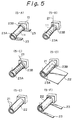
- each bobbin 10 is shown schematically. One of the rim portions 12 thereof is omitted from each drawing to make them more understandable.
- narrow insulating strips 23 having a predetermined width are wound on both side edge portions of the body portion 11 to form ridged portions 23A and 23B, respectively (as shown in Fig. 5-A).
- the wiring material 21 is folded on the surface of the insulating tape 22 toward the terminal 14 (as shown in Fig. 5-D).
- two further narrow insulating strips 23 having a predetermined width are wound on the two end portions of the insulating tape 22 to form two further ridged portions 23A and 23B (as shown in Fig. 5-F).
- a wiring coil is produced provided with a plurality of wiring layers, as shown in Fig. 3.
- the wiring coil thus produced includes the narrow insulating strips 23 which form the ridged portions 23A and 23B as insulated layers.
- the narrow insulating strips have extremely small stiffness and strength since they are 0.05 to 1.0mm in thickness and 2 to 10mm in width.
- the insulating strips 23 are wound on the bobbin 10 or on a surface of the wiring material 21, the insulating strips 23 are twisted even with a slight tension applied thereto. This makes it difficult for the insulating strips 23 to be wound precisely on a predetermined place.
- tension when tension is applied to the insulating strips 23, they are deformed, for example, are reduced in the thickness or the width, or are broken, to make it difficult to form a predetermined insulating layer.
- insulating strips having relatively high stiffness and strength should be used. Further, the operator should wind the insulating strips on the bobbin with a great care so as not to apply unnecessary tension thereto.
- the object of the present invention is to provide an insulating tape for winding coils which facilitates accurate winding of insulated strips on a bobbin or the like in a wiring coil producing method and further enables the winding operation to be carried out automatically.
- an insulating tape for winding coils which includes a guide sheet having a predetermined width and a plurality of narrow insulating strips provided with adhesive on both surfaces thereof and removably connected to the guide sheet at predetermined spaces.
- the insulating tape 1 for winding coils of the present invention includes guide sheet 2 having a predetermined width and a plurality of narrow insulating strips 3 provided with adhesive on both surfaces thereof and removably connected to the guide sheet at predetermined spaces.
- the guide (release) sheet 2 is made of a nonadhesive sheet-like material, such as paper or plastic film.
- the insulating strips 3 are preferably made of an epoxy resin impregnated fabric tape. In the illustrated case they are provided along the edge margins of the sheet 2.
- the insulating tape for winding coils 1 of the present invention is wound on a reel 4 or the like made of paper or plastic. At one end, there is a portion on which the narrow insulating strips 3 are not provided, to form a portion 2a to be wound on a winding reel 5.
- the reel 4 on which the insulating tape is wound is mounted on a chuck (not shown) rotatably supported on a machine frame (not shown) or a movable arm (not shown) moving in both vertical and horizontal directions, then the end of the guide sheet 2 is withdrawn from the reel 4 and wound on a reel 5.
- the narrow insulating strips 3 are wound on a bobbin 10 while moving a pressing means 30 or a movable arm to a surface of the bobbin 10 or a surface of wound insulated tape 22 to make the insulating strips 3 contact the surface while the bobbin is rotated.
- the insulating strips 3 are adhered to the end surfaces of the bobbin in predetermined lengths by the rotation of the bobbin 10 to form the ridge portions 3A and 3B, respectively.
- the rotation of the bobbin is stopped.
- the pressing means 30 is removed from a contact position X at which the insulating strips 3 contact the surface of the bobbin and is moved to a position Y at which the insulating strips 3 do not contact the surface of the bobbin.
- the insulating strips 3 are cut with a suitable cutter (not shown).
- the bobbin 10 is started rotating to wind the wiring material 21 delivered from a reel 40 through a suitable guide member 41 onto the surface of the bobbin 10 and between the ridge portions 3A and 3B.
- insulating tape 22 delivered from a reel 30 through a suitable guide member 31 is wound on the bobbin 10 to cover the wiring material 21 and the ridge portions 3A and 3B.
- a portion of the wiring material 21 is folded on the surface of the insulating tape 22 and covered with the tape 22 during the sheet winding operation as shown in Figs. 5-D and 5-E.
- the pressing means 30 is again moved to the position X to bring the insulating strips 3 into contact with the surface of the insulating sheet previously wound thereto and covering a portion of the wiring material 21 to form stacked ridge portions.
- the guide sheet 2 provided with the insulating strips 3 is guided by the rim portions 12 and 13 of the bobbin.
- the insulating tape 1 of the present invention includes a guide sheet 2 having a wide width and a plurality of narrow insulating strips provided with adhesive on both surfaces thereof and since the guide sheet 2 has relatively high stiffness and high strength, there is no deformation or twisting due to tension or other external force applied thereto.
- the narrow insulating strips can be accurately wound on the surface portion of the bobbin alongside the rim portions 12 and 13.
- the guide sheet 2 is wound on the reel 5 after the narrow insulating strips 3 are removed therefrom and wound on the surface of the bobbin 10.
- the narrow insulating strips can be precisely wound at predetermined defined positions of the bobbin just by arranging an end of the guide sheet at a predetermined winding position with respect to the bobbin.
- an insulating layer having predetermined dimensions can be formed without deformation or twisting of the narrow insulating strips caused by tension or the like in the winding operation, since the narrow insulating strips are placed on the guide sheet.
- the operation for winding the narrow insulating strips on the surface of the bobbin can be carried out utilizing an automatic apparatus, resulting in improved production efficiency in the wiring coil production.
Landscapes
- Engineering & Computer Science (AREA)
- Power Engineering (AREA)
- Manufacturing & Machinery (AREA)
- Insulating Of Coils (AREA)
Priority Applications (3)
| Application Number | Priority Date | Filing Date | Title |
|---|---|---|---|
| EP90312424A EP0489987B1 (fr) | 1990-11-14 | 1990-11-14 | Bande isolante pour l'enroulement de bobines |
| DE1990616444 DE69016444T2 (de) | 1990-11-14 | 1990-11-14 | Isolierband zum Wickeln von Spulen. |
| US07/839,688 US5284541A (en) | 1990-11-13 | 1992-02-24 | Insulating tape for winding coils |
Applications Claiming Priority (1)
| Application Number | Priority Date | Filing Date | Title |
|---|---|---|---|
| EP90312424A EP0489987B1 (fr) | 1990-11-14 | 1990-11-14 | Bande isolante pour l'enroulement de bobines |
Publications (2)
| Publication Number | Publication Date |
|---|---|
| EP0489987A1 true EP0489987A1 (fr) | 1992-06-17 |
| EP0489987B1 EP0489987B1 (fr) | 1995-01-25 |
Family
ID=8205610
Family Applications (1)
| Application Number | Title | Priority Date | Filing Date |
|---|---|---|---|
| EP90312424A Expired - Lifetime EP0489987B1 (fr) | 1990-11-13 | 1990-11-14 | Bande isolante pour l'enroulement de bobines |
Country Status (2)
| Country | Link |
|---|---|
| EP (1) | EP0489987B1 (fr) |
| DE (1) | DE69016444T2 (fr) |
Cited By (2)
| Publication number | Priority date | Publication date | Assignee | Title |
|---|---|---|---|---|
| CN102623170A (zh) * | 2012-04-16 | 2012-08-01 | 珠海市艾森科技有限公司 | 安装于自动绕线机的自动包胶装置 |
| CN103258637A (zh) * | 2013-05-07 | 2013-08-21 | 深圳市泰顺友电机电有限公司 | 一种多头自动绕线包胶一体机 |
Citations (1)
| Publication number | Priority date | Publication date | Assignee | Title |
|---|---|---|---|---|
| US4269367A (en) * | 1978-04-14 | 1981-05-26 | Tokyo Shibaura Denki Kabushiki Kaisha | Coil winding machine |
-
1990
- 1990-11-14 DE DE1990616444 patent/DE69016444T2/de not_active Expired - Fee Related
- 1990-11-14 EP EP90312424A patent/EP0489987B1/fr not_active Expired - Lifetime
Patent Citations (1)
| Publication number | Priority date | Publication date | Assignee | Title |
|---|---|---|---|---|
| US4269367A (en) * | 1978-04-14 | 1981-05-26 | Tokyo Shibaura Denki Kabushiki Kaisha | Coil winding machine |
Non-Patent Citations (4)
| Title |
|---|
| PATENT ABSTRACTS OF JAPAN, vol. 10, no. 213 (E-422)[2269], 25th July 1986; & JP-A-61 053 713 (HITACHI) 17-03-1986 * |
| PATENT ABSTRACTS OF JAPAN, vol. 3, no. 145 (E-155), 30th November 1979; & JP-A-54 124 216 (HITACHI SEISAKUSHO K.K.) 27-09-1979 * |
| PATENT ABSTRACTS OF JAPAN, vol. 3, no. 288 (E-781)[3636], 30th June 1989; & JP-A-1 071 112 (DENKI ONKYO) 16-03-1989 * |
| PATENT ABSTRACTS OF JAPAN, vol. 8, no. 81 (E-238)[1518], 13th April 1984; & JP-A-59 002 307 (MEIJI NATIONAL KOGYO K.K.) 07-01-1984 * |
Cited By (3)
| Publication number | Priority date | Publication date | Assignee | Title |
|---|---|---|---|---|
| CN102623170A (zh) * | 2012-04-16 | 2012-08-01 | 珠海市艾森科技有限公司 | 安装于自动绕线机的自动包胶装置 |
| CN103258637A (zh) * | 2013-05-07 | 2013-08-21 | 深圳市泰顺友电机电有限公司 | 一种多头自动绕线包胶一体机 |
| CN103258637B (zh) * | 2013-05-07 | 2015-04-22 | 深圳市泰顺友电机电有限公司 | 一种多头自动绕线包胶一体机 |
Also Published As
| Publication number | Publication date |
|---|---|
| EP0489987B1 (fr) | 1995-01-25 |
| DE69016444D1 (de) | 1995-03-09 |
| DE69016444T2 (de) | 1995-05-24 |
Similar Documents
| Publication | Publication Date | Title |
|---|---|---|
| EP0003647B1 (fr) | Corps de bobine et procédé pour réaliser des connexions d'enroulement | |
| US4780157A (en) | Method and apparatus for manufacturing transposed ribbon cable and electromagnetic device | |
| GB2062363A (en) | Coils for electric motors | |
| JPH0462142A (ja) | ロービング材自動積層装置 | |
| EP0486202A2 (fr) | Couche de base pour une bobine à fibre optique | |
| EP0643468A1 (fr) | Procédé et appareil pour la production d'armature à équilibrage amélioré pour machine dynamo-électrique | |
| US4658090A (en) | Ribbon cable, a transposed ribbon cable, and a method and apparatus for manufacturing transposed ribbon cable | |
| US5284541A (en) | Insulating tape for winding coils | |
| EP0489987A1 (fr) | Bande isolante pour l'enroulement de bobines | |
| JPH05298939A (ja) | フラットケーブル及びその製造方法 | |
| US4151964A (en) | Apparatus and method for manufacture of bell-shaped armatures | |
| JP2002246278A (ja) | 積層体、その製造装置及び製造方法、並びに、電気二重層コンデンサ | |
| GB1362844A (en) | Method of making an electrostatic wire stylus recording head and lead wires therefor | |
| US4979292A (en) | Method of forming filament harness | |
| US4888071A (en) | Method for manufacturing ribbon cable and transposed cable | |
| JP4402757B2 (ja) | 平形導線の巻線コイルの製造方法及び装置 | |
| JPH0749692Y2 (ja) | 巻線コイル用絶縁テープ | |
| US4948454A (en) | Process and apparatus for the application of a non-adhesive insulating tape to an electric coil winding | |
| JP2747256B2 (ja) | コイルの巻線方法 | |
| JPH07336834A (ja) | 複層絶縁電線の絶縁剥離装置 | |
| JP3070026B2 (ja) | コイルリード引出線の固定方法 | |
| US2941129A (en) | Electrical coil | |
| JPH04229608A (ja) | コイル枠 | |
| EP0274173A1 (fr) | Câble-ruban, câble-ruban transposé, et méthode et appareil pour sa fabrication et dispositif électromagnétique | |
| JPS6152620B2 (fr) |
Legal Events
| Date | Code | Title | Description |
|---|---|---|---|
| PUAI | Public reference made under article 153(3) epc to a published international application that has entered the european phase |
Free format text: ORIGINAL CODE: 0009012 |
|
| 17P | Request for examination filed |
Effective date: 19910923 |
|
| AK | Designated contracting states |
Kind code of ref document: A1 Designated state(s): DE GB |
|
| 17Q | First examination report despatched |
Effective date: 19930308 |
|
| GRAA | (expected) grant |
Free format text: ORIGINAL CODE: 0009210 |
|
| AK | Designated contracting states |
Kind code of ref document: B1 Designated state(s): DE GB |
|
| REF | Corresponds to: |
Ref document number: 69016444 Country of ref document: DE Date of ref document: 19950309 |
|
| PLBE | No opposition filed within time limit |
Free format text: ORIGINAL CODE: 0009261 |
|
| STAA | Information on the status of an ep patent application or granted ep patent |
Free format text: STATUS: NO OPPOSITION FILED WITHIN TIME LIMIT |
|
| 26N | No opposition filed | ||
| PGFP | Annual fee paid to national office [announced via postgrant information from national office to epo] |
Ref country code: GB Payment date: 19981104 Year of fee payment: 9 |
|
| PGFP | Annual fee paid to national office [announced via postgrant information from national office to epo] |
Ref country code: DE Payment date: 19981228 Year of fee payment: 9 |
|
| PG25 | Lapsed in a contracting state [announced via postgrant information from national office to epo] |
Ref country code: GB Free format text: LAPSE BECAUSE OF NON-PAYMENT OF DUE FEES Effective date: 19991114 |
|
| GBPC | Gb: european patent ceased through non-payment of renewal fee |
Effective date: 19991114 |
|
| PG25 | Lapsed in a contracting state [announced via postgrant information from national office to epo] |
Ref country code: DE Free format text: LAPSE BECAUSE OF NON-PAYMENT OF DUE FEES Effective date: 20000901 |