EP0490084A2 - Dispositif pour l'emballage ou le déballage de récipients - Google Patents
Dispositif pour l'emballage ou le déballage de récipients Download PDFInfo
- Publication number
- EP0490084A2 EP0490084A2 EP91119027A EP91119027A EP0490084A2 EP 0490084 A2 EP0490084 A2 EP 0490084A2 EP 91119027 A EP91119027 A EP 91119027A EP 91119027 A EP91119027 A EP 91119027A EP 0490084 A2 EP0490084 A2 EP 0490084A2
- Authority
- EP
- European Patent Office
- Prior art keywords
- rotary element
- gripper
- gripper head
- link
- heads
- Prior art date
- Legal status (The legal status is an assumption and is not a legal conclusion. Google has not performed a legal analysis and makes no representation as to the accuracy of the status listed.)
- Granted
Links
Images




Classifications
-
- B—PERFORMING OPERATIONS; TRANSPORTING
- B65—CONVEYING; PACKING; STORING; HANDLING THIN OR FILAMENTARY MATERIAL
- B65G—TRANSPORT OR STORAGE DEVICES, e.g. CONVEYORS FOR LOADING OR TIPPING, SHOP CONVEYOR SYSTEMS OR PNEUMATIC TUBE CONVEYORS
- B65G47/00—Article or material-handling devices associated with conveyors; Methods employing such devices
- B65G47/74—Feeding, transfer, or discharging devices of particular kinds or types
- B65G47/90—Devices for picking-up and depositing articles or materials
- B65G47/904—Devices for picking-up and depositing articles or materials provided with rotary movements only
-
- B—PERFORMING OPERATIONS; TRANSPORTING
- B65—CONVEYING; PACKING; STORING; HANDLING THIN OR FILAMENTARY MATERIAL
- B65B—MACHINES, APPARATUS OR DEVICES FOR, OR METHODS OF, PACKAGING ARTICLES OR MATERIALS; UNPACKING
- B65B21/00—Packaging or unpacking of bottles
- B65B21/02—Packaging or unpacking of bottles in or from preformed containers, e.g. crates
- B65B21/14—Introducing or removing groups of bottles, for filling or emptying containers in one operation
- B65B21/18—Introducing or removing groups of bottles, for filling or emptying containers in one operation using grippers engaging bottles, e.g. bottle necks
- B65B21/183—Introducing or removing groups of bottles, for filling or emptying containers in one operation using grippers engaging bottles, e.g. bottle necks the grippers moving in an endless path
Definitions
- the invention relates to a device for packing or unpacking containers, with a rotation element which can be rotated about a substantially horizontal axis and to which container gripper heads for repetitively passing through a closed spell containing an access position and a grip release position are attached at locations remote from the axis of rotation.
- Devices of this type are preferably used in the beverage industry for packaging bottles in carrier boxes or for unloading the carrier boxes. It is important that, despite the highest possible packing performance, which is associated with high transport speeds and consequently high acceleration and braking forces acting on the bottles, the bottles and boxes are handled gently. In particular, it must be prevented that frequent bottle breakage leads to malfunctions in the operation.
- a device for packaging containers of the type mentioned is known from DE-PS 10 87 967.
- three gripping heads suspended from the rotary element in the manner of a gondola can be moved in a vertical plane, the gripping heads being suspended on rails or pivot arms projecting laterally from the rotating element in such a way that, in addition to the movement in a vertical plane, also a horizontal movement the gripping heads can be done.
- An access position and a handle release position each result approximately in the most lowered position of the gripping heads. For example, in order to load bottles into a carrier box, a gripping head, in its most lowered position, accesses bottles conveyed to this access position.
- the gripping head in question is moved horizontally, so that the gripping head is positioned over a spine adjacent to the bottle conveying path, on which a carrier box to be filled is transported.
- the gripping head which has placed its bottles in the carrier box, to take up new bottles again, it has to make a further rotation by 360 ° during which there is a horizontal shifting back and alignment to the conveyor belt that delivers the bottles.
- a disadvantage of this known device for packaging containers is that the packing frequency is impaired by the fact that a complete circulation of the empty gripping head is necessary in order to be able to carry out a new loading of the gripping head with bottles.
- this object is achieved in that the container gripper heads are connected to the rotary element in each case via a relative movement of the gripper head against the rotary element in a substantially vertical plane, and a drive and control device for pivoting the gripper heads relative to the rotary element to produce the path in a desired shape is provided.
- a path curve can be generated with the device according to the invention in such a way that both the vertical and the horizontal speed of the gripper head are greatly reduced in the access position and the grip release position of the gripper head, and a vertical movement takes place in such a way that no particular control of the movement of the boxes or of the delivered bottles is necessary to ensure safe access or safe storage of the bottles in the crate.
- the solution according to the invention makes it unnecessary to accelerate the bottles delivered and adapt them to the rotational speed of the gripper heads Form groups of bottles to be packed. Rather, the bottles can be delivered continuously, with the gripper head picking up the foremost bottles of the bottle column being conveyed. In the vicinity of the access position or access release position, in particular, a kind of diving movement of the gripper head can be ensured, by means of which it is possible that the bottles can be lowered into the individual compartments of a carrier box without a large fall distance.
- the device has a device for parallel guidance of the gripper heads in a horizontal orientation.
- a parallel guide advantageously prevents the gripper heads suspended in the manner of a gondola from vibrating during the packing operation, and thus the bottles cannot be gripped or the bottles placed in the boxes in an orderly manner.
- a link element is provided as the suspension and the drive and control device comprises a roller star gear, a desired trajectory curve being generated by appropriate formation of the toothed path of the roller star gear.
- the tooth path of the roller star gear is fixed, and a roller star engages in the tooth path, which is connected to a shaft mounted on the rotary element, which in turn drives a shaft via a gear that is connected to a link element.
- the rotary element is preferably provided as a turntable on which three or four gripper heads are provided, the respective articulation points of the associated link element being at the same distance from the turntable Axis of rotation of the turntable and are arranged at the same angular distance from one another.
- a suspension comprising two link members, one of the two link members having a cam element which engages in a fixed curved groove, and the other link element is connected to the rotary element via a two-part auxiliary link linkage.
- One of the two links of the auxiliary linkage is provided with a cam element which engages in a second fixed cam groove.
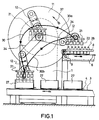
- the reference numeral 1 designates a base frame on which a rotor 11 is rotatably mounted on a fixed axis 10.
- the axis 10 is secured against rotation relative to the frame 1 by a cam 28 engaging in a safety switch 29.
- the rotor 11 is designed in the form of a hollow turntable, in the interior of which several gears are arranged, of which the gear 14 is shown. On the transmission will be discussed in more detail later. With 19 an oil sump is designated, which forms at the lower end of the interior formed in the rotor 11.
- the rotor 11 is driven by a motor gear unit 2, which comprises a drive pinion 18 which engages in a ring gear 17 connected to the rotor 11.
- the gripper head 21 is rigidly connected to a shaft 20 which is rotatably mounted in the link element 12.
- the gripper head 21 comprises pneumatically operated gripper tulips 22 and is provided with a centering frame 23, which can be displaced vertically relative to the gripper head 21, controlled by a cam cam 24.
- the cam disc 24 is rigidly connected to the link element 12 and a roller 31 connected to the centering frame 23 rolls on the cam disc.
- the fixed shaft 10 is rigidly connected to a pinion 32, which drives a pinion 25 via a chain element 34, for example via a toothed belt, which is arranged so as to be rotatable on the axis 13.
- the pinion 25 is designed as a double pinion and is in drive connection via a further chain element 35 with a pinion 33 which is fixedly connected to the shaft 20.
- the pinions 32, 25 and 33 have matching numbers of teeth.
- shafts 36 are mounted in the rotor 11, a drive connection being made between the shafts 36 and the shafts 13 by a gear, such as the gear 14.
- the waves 36 are rigidly connected to a roller star 15, which engages in a stationary annular groove 16, in which tooth arrangements are provided on one or both side walls for engagement with the roller star 15.
- the drive connection between the pinion 32 and the pinion 33 via the chain element 34, the double pinion 25 and the chain element 35 ensures that each gripper head is in a constant position during the rotation of the rotor 11 remains aligned, the device being adjusted so that all gripper heads are aligned in a horizontal position regardless of their position on the web 30.
- the roller 31 of the centering frame rolls on the cam plate 24 connected to the lanker element when the link elements 12 move, so that the frame relative to the shape of the cam plate is relative is moved vertically to the gripper head.
- the shape of the cam plate 24 is provided so that the centering frame is moved down shortly before the bottles are lowered into the boxes, so that the boxes can be brought into a defined position for lowering the bottles by the centering frame.
- the link elements 12 move relative to the turntable, which always rotates in a direction indicated by the arrow 37 in Fig. 1, that a gripper head 21, which has just picked up bottles 26 from the bottle conveyor 6, on one by a pivoting movement in the opposite Direction of rotation to the direction of rotation of the rotor 11 generated web section 30a is moved to a carrier box 27 arranged in a suitable position.
- a loop path is provided directly above the carrier box 27, whereby the gripper head is immersed in the Ben box, and the bottles can be gently placed in the box by the gripper head without falling from a greater height.
- both the horizontal and vertical speed components of the gripper head are greatly reduced in this track section, while on the vast majority of the track section from the Access position to the handle release position to achieve a high packing frequency, the bottle can be transported at a higher speed.
- the link elements 12 By suitably controlling the movement of the link elements 12, it can be ensured that no excessive acceleration or deceleration values occur in front of or behind the access or grip release position.
- the path 30b runs in such a way that the gripper head is moved over the stop 9 and then, by again providing a loop in the path of the gripper head, the gripper head is lowered to the bottles 26 to be gripped.
- both the horizontal and vertical speed components of the gripper head are greatly reduced compared to the other web sections. After grasping the bottles, the described passage is repeated.
- a box 27 is loaded by each of the three gripper heads 21 in the packing device shown in FIGS. 1 and 2, whereby a high packing frequency is achieved.
- the packing process can be designed without high acceleration and deceleration values and, in particular, without jerking, thereby protecting the packaging goods and the packaging containers, which also has an advantageous effect on the wear of the packaging device.
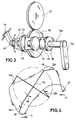
- FIG. 3 shows a drive device for a link element 12a, which instead of the drive device shown in FIGS. 1 and 2 with the gear 14 and the roller star gear could be used.
- the same or equivalent parts are therefore designated in FIG. 3 with the same reference numbers provided with an index a as in FIGS. 1 and 2.
- the drive device of FIG. 3 comprises a fixed gear 37, which would have to be arranged concentrically to the axis of rotation 10 in the device shown in FIGS. 1 and 2.
- the fixed gear 37 is in engagement with a gear 38 which is rotatable about an axis 13a which is mounted on a rotor (not shown in FIG. 3) and which in turn is in a gear 42 which is rotatable about an axis 45 and is rigidly connected to it , intervenes.
- a gear 41 which is in drive engagement via an intermediate gear 40 with a gear rotatable about the axis 13a.
- the gear 39 is rigidly connected to the axle 13a, which in turn is rigidly connected to the link element 12a.
- the gear 39 and thus the armature element 12a can be rotated against the gear 38.
- the axis 45 has at its end opposite the gear 41 a cam element 43 in the form of a roller which engages in a groove 44.
- the groove 44 is arranged in a stationary manner like the groove 16 shown in FIGS. 1 and 2, is also closed in itself, but differs from a circular circulation guideway in contrast to the groove 16.
- the axis 45 and the intermediate gear 40 are rotatably mounted in a rocker 70, which in turn is pivotally mounted on the axis 13a.
- FIG. 4 Another possible curved path for a gripper head is shown in FIG. 4.
- This cam track could be generated both with the drive device for the handlebar elements described in FIGS. 1 and 2 and with the device according to FIG. 3.
- 4 shows a rotor 11a which is provided for moving four gripper heads via four link elements 12b.
- 47 is a bottle access position and 46 a handle release position.
- no loop is provided at the handle release position.
- the horizontal as well as the vertical component of the speed of the gripper heads in the vicinity of the access position and also in the vicinity of the handle release position are greatly reduced compared to the majority of the other path sections.
- gearwheels which are connected to shafts 13c, the shafts 13c on the rotary element 11c are mounted and in turn are connected to link elements 12c.
- four gearwheels 61 and accordingly four link elements are provided for holding four gripper heads (not shown in FIGS. 5 and 6).
- the gearwheels 61 are in engagement with gearwheels 57 which are rotatably supported on shafts 55, the shafts 55 in turn being rotatably supported on the rotating element 11c.
- a clutch disc 59 is slidably disposed on the shaft 55.
- the clutch disc 59 has protruding bolts 60 for engagement in corresponding bores 58 in the gear 57. At a distance from the clutch disc 59, another gear 56 is arranged on the shaft 55 in a rotationally fixed manner. Between the further gear wheel 56 and the clutch disc 59, a helical spring 62 is provided, the ends of which abut the gear wheel 56 and the clutch disc 59. The gear wheel 56 is in engagement with a toothed segment 54 which is attached in a rotationally fixed manner on a shaft 54a which in turn is rotatably mounted on the rotary element 11c.
- the toothed segment 54 has a pin element 54b which projects through a slot opening 66 in the wall of the rotary element designed as a hollow body in the present exemplary embodiment and engages with a roller in a groove curve 52 which is formed in a fixed cam ring 50 fastened to the base frame 1c of the device is.
- an angle lever is designated by 64, which is firmly connected to a shift fork 63 which engages in an annular groove formed in the peripheral surface of the clutch disc 59.
- the angle lever 64 is guided with its end facing away from the shift fork 63 into an opening 65 in the wall of the rotary element 11c and has at this end a roller 64a with which it bears against a stroke curve 51 formed on the stationary cam ring 50.
- Designated at 68 is a lever which has a projecting pin element 68a at one end, which is guided through an opening 66a in the wall of the rotary element 11c and engages in a further cam groove 53 which is formed in the stationary cam ring 50.
- the lever 68 is fixedly connected at its other end to a shaft 68b which is supported at its ends on the rotary element 11c is.
- a further lever 67 is fastened to the shaft 68b and, at its end opposite the fastening point, can engage with a hook-like projecting part in a recess in the gearwheel 57.
- the spring 62 presses the clutch disk 59 with its projecting bolts 60 into the bores 58 of the gearwheel 57, so that movements transmitted through the pin element 54b to the toothed segments 54 via the gearwheel 56 and the shaft 55 onto the gearwheel 57, and thus from the gear 57 can be transferred via the gear 61 to the lanker elements 12c, so that a suitable movement of the gripper heads suspended on the link elements 12c is possible in accordance with the course of the curved groove 52.
- the coupling and locking mechanism described is provided to ensure that the lever 12c can rotate continuously in one direction relative to the rotating element 11c and not, as the device of Figures 5 and 6 would otherwise only allow without these devices, oscillating Movements.
- the rotary element 11d is cruciform and a significant difference from the previously described embodiments is that two interconnected lanker elements 103 and 104 are used as the suspension for the gripper heads.
- the inner link element 103 can be pivoted against the rotary element 11d, while the outer link element 104 in turn can be pivoted against the inner link element 103.
- auxiliary links 105 and 106 are pivotally connected to one another, the auxiliary link 105 being pivotally connected to the rotary element 11d and the auxiliary link 106 being pivotally connected to the outer link 104, the pivot point in the present exemplary embodiment being radially in front of the pivot point of the inner link 103 to the outer link 104 is arranged.
- the inner link 103 has a cam element 103a which engages in a cam groove 101 which is formed in a fixed cam plate 100 which is connected to the base frame 1d.
- the auxiliary link 105 is provided with a cam element 105a which engages in a second cam groove 102 formed in the cam disk 100.
- the cam elements 103a and 105a are positively guided in the grooves 101 and 102, as a result of which an additional movement in a vertical plane of the gripper heads 21d relative to the rotation of the rotary element 11d and thus a curved path 107 suitable for packaging is achieved.
- the gripper heads are compared to those with respect to this additional movement Embodiments described above more possibilities, so that a curved path can be achieved even further with respect to spatial adaptation options and suitable speed and acceleration values.
- a parallel guidance of the gripper heads 21d by a fixed pinion and toothed belt driven by this is possible similar to FIG. 2. All that is required is an additional toothed belt from the articulation point of the outer link 104 on the inner link 103 to the articulation point of the gripper head 21d on the outer link 104 with two additional pinions.
- a particularly compact design of the four belt drives is possible if a central, fixed sun gear 108 is provided concentrically to the axis of rotation of the rotating element 11d, into which four planet gears 109, which are mounted in the arms of the rotating element 11d, engage, each of which drives the drive pinion 34d of the belt drives to the gripper heads 21d rotated. This is indicated by dash-dotted lines in FIG. 7.
- the above-described exemplary embodiments each show devices for packing bottles 26 into carrier boxes 27.
- the conveyors 6, 6d for the bottles 26 and the conveyors 3, 3d for the carrier boxes 27 result from these devices Devices for unpacking the bottles 26 from the carrier boxes 27.
- the links 103 to 106 are also to be articulated in mirror image fashion on the rotating element 11d in order to maintain the favorable engagement conditions of the rollers 103a, 105a in the cam tracks 101, 102.
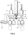
- an additionally movable gripper head as shown in FIG. 8, can be used.
- 80 denotes a carrier plate which can be connected via a shaft 85 to a suspension in accordance with the exemplary embodiments described above.
- the carrier plate 80 has two guide bushings 81, into which corresponding guide rods 82 connected to a gripper head 87 engage.
- a pneumatic cylinder 83 is also arranged on the carrier plate 80, the piston of which is connected to a carrier plate 88 of the gripper head 87 via a connecting piece 86.
- Tulip-like gripping elements 84 are attached to the carrier plate 88 of the gripper head 87.
- the path curve of the gripper head 87 can be further influenced, in particular by additionally moving the gripper head 87 perpendicular to the carrier plate 80 and thus a vertical displacement of the gripper head 87 during phases of accessing or releasing container groups
- the gripper head is kept constantly horizontal, which is sufficient to ensure that the containers are gripped securely or set down gently.
- a broken position of the gripper head 87 is indicated in FIG. 8 by the dashed lines.
- the pneumatic cylinder for generating the additional movement of the gripper head can be controlled by sensors which detect the respective angular position of the rotary element and thus also the respective position of the gripper heads.
- the shift is described as occurring around a vertical direction.
- this shift in the horizontal direction is also possible to do this shift in the horizontal direction to be carried out with the same means or to perform an inclined movement, that is to say a tilting movement about a horizontal axis.
- reference number 89 denotes a conveyor device with hinge chains which is driven synchronously with the rotary element and on which bottles 90 to be packaged are conveyed in a plurality of parallel rows in accordance with the direction of arrow 99 against a stop rod 91.
- the stop rod 91 is provided as part of a swivel bracket 98 with swivel arms 92 that can be swiveled about an axis of rotation 94.
- a pin element 93 is attached to at least one of the bracket legs 92 and engages in a groove curve 96 of a turntable 95 which can be rotated about an axis of rotation 97 in synchronism with the rotary element.
- the bottles 90 which are conveyed abut the stop bar 91 approximately in the position of the swivel bracket 98 indicated by dashed lines, at which point, controlled by the rotary movement of the turntable 95 with the groove curve 96, the speed of the stop bar 91 is somewhat lower than the speed of the bottles delivered, so that a relatively gentle stop, which is gentle on the bottles, takes place.
- the stop rod 91 then moves in the direction of arrow 99 under the rotation of the turntable 95 at a constant speed.
- the conveying by the conveying device 89 continues at a constant, somewhat higher speed, so that during this phase the bottles 90 align with one another by coming to a stop in the conveying direction.
- the side guides not shown in FIG.
Landscapes
- Engineering & Computer Science (AREA)
- Mechanical Engineering (AREA)
- Wrapping Of Specific Fragile Articles (AREA)
- Specific Conveyance Elements (AREA)
Applications Claiming Priority (4)
| Application Number | Priority Date | Filing Date | Title |
|---|---|---|---|
| DE4036038 | 1990-11-13 | ||
| DE4036038 | 1990-11-13 | ||
| DE4125573 | 1991-08-02 | ||
| DE4125573A DE4125573A1 (de) | 1990-11-13 | 1991-08-02 | Vorrichtung zum ein- oder auspacken von behaeltern |
Publications (3)
| Publication Number | Publication Date |
|---|---|
| EP0490084A2 true EP0490084A2 (fr) | 1992-06-17 |
| EP0490084A3 EP0490084A3 (en) | 1992-10-14 |
| EP0490084B1 EP0490084B1 (fr) | 1995-06-07 |
Family
ID=25898438
Family Applications (1)
| Application Number | Title | Priority Date | Filing Date |
|---|---|---|---|
| EP91119027A Expired - Lifetime EP0490084B1 (fr) | 1990-11-13 | 1991-11-07 | Dispositif pour l'emballage ou le déballage de récipients |
Country Status (7)
| Country | Link |
|---|---|
| US (1) | US5257888A (fr) |
| EP (1) | EP0490084B1 (fr) |
| JP (1) | JP2527867B2 (fr) |
| BR (1) | BR9104897A (fr) |
| CA (1) | CA2055234C (fr) |
| DE (2) | DE4125573A1 (fr) |
| ES (1) | ES2073095T3 (fr) |
Cited By (8)
| Publication number | Priority date | Publication date | Assignee | Title |
|---|---|---|---|---|
| EP0638478A1 (fr) * | 1993-07-23 | 1995-02-15 | KRONES AG Hermann Kronseder Maschinenfabrik | Dispositif pour tirer des récipients d'emballages de transport |
| WO1996032323A3 (fr) * | 1995-04-10 | 1996-12-19 | Christian Metges | Procede et dispositif pour emballer et pour deballer des recipients dans des caisses |
| EP0756994A1 (fr) * | 1995-08-02 | 1997-02-05 | KHS Maschinen- und Anlagenbau Aktiengesellschaft | Machine d'emballage pour introduire ou enlever des groupes de bouteilles ou récipients similaires dans ou hors des caisses pour bouteilles ou emballages similaires |
| DE102004016838A1 (de) * | 2004-04-01 | 2005-10-27 | Wanfried-Druck Kalden Gmbh | Verfahren und Vorrichtung zum Ausrichten von Gefäßen für flüssige oder fließfähige Medien, insbesondere Getränke |
| DE102008047414A1 (de) * | 2008-09-16 | 2010-04-08 | Leica Biosystems Nussloch Gmbh | Vorrichtung zur Behandlung von Präparaten |
| ITUB20154226A1 (it) * | 2015-10-08 | 2017-04-08 | Gima Spa | Stazione di prelievo e consegna di fogli sagomati definenti corpi scatolari di differente tipologia |
| EP4378839A1 (fr) * | 2022-11-30 | 2024-06-05 | Tetra Laval Holdings & Finance S.A. | Appareil pour remplir des emballages alimentaires |
| CN119706322A (zh) * | 2024-11-14 | 2025-03-28 | 因湃电池科技有限公司 | 工件抓取设备的控制方法、工件抓取设备及存储介质 |
Families Citing this family (56)
| Publication number | Priority date | Publication date | Assignee | Title |
|---|---|---|---|---|
| DE4204993C1 (fr) * | 1992-02-19 | 1993-02-25 | Krones Ag Hermann Kronseder Maschinenfabrik, 8402 Neutraubling, De | |
| DE4242163C2 (de) * | 1992-12-15 | 2001-06-21 | Krones Ag | Verfahren zum Behandeln von Gefäßen und Anlage zu dessen Durchführung |
| DE4243010C1 (de) * | 1992-12-19 | 1994-05-26 | Kronseder Maschf Krones | Packmaschine |
| DE4243008C1 (de) * | 1992-12-19 | 1994-01-20 | Kronseder Maschf Krones | Packmaschine |
| DE4307906C1 (de) * | 1993-03-12 | 1994-07-07 | Vetter & Co Apotheker | Vorrichtung zur taktweisen Bearbeitung von Gegenständen, insbes. von Zylindern für medizinische Spritzen |
| DE4414001A1 (de) * | 1993-04-23 | 1994-10-27 | Kronseder Maschf Krones | Palettiermaschine |
| DE4323736C2 (de) * | 1993-07-15 | 1996-01-18 | Felsomat Gmbh & Co Kg | Handhabungsvorrichtung |
| DE4332342A1 (de) * | 1993-09-23 | 1995-03-30 | Kronseder Maschf Krones | Verfahren und Packmaschine zum Entnehmen von Gefäßen aus Transportbehältern |
| US20030106288A1 (en) * | 1994-11-10 | 2003-06-12 | Hartness Thomas Patterson | Continuous circular motion case packing and closure apparatus and method |
| US6571532B1 (en) | 1994-11-10 | 2003-06-03 | Hartness International, Inc. | Continuous motion case packing apparatus and method |
| US5588282A (en) * | 1994-11-10 | 1996-12-31 | Hartness International, Inc. | Continuous motion case packing apparatus and method |
| US6729103B1 (en) * | 1994-11-10 | 2004-05-04 | Hartness International, Inc. | Continuous circular motion case packing and depacking apparatus and method |
| US6883296B2 (en) | 1994-11-10 | 2005-04-26 | Hartness International, Inc. | Case tab-lock slitting and flap sealer in combination with a continuous radial motion case packing apparatus and method |
| DE19700150A1 (de) * | 1997-01-06 | 1998-07-09 | Focke & Co | Vorrichtung zum Befüllen von Kartons |
| SE514070C2 (sv) * | 1999-04-30 | 2000-12-18 | Norden Pac Dev Ab | Förfarande och anordning för överförande av förpackningar från en första intermittent arbetande enhet andra kontinuerligt arbetande enhet |
| DE29914444U1 (de) * | 1999-08-20 | 2000-04-13 | KRONES AG, 93073 Neutraubling | Greiftulpe für Bügelverschlußflaschen |
| US6443812B1 (en) * | 1999-08-24 | 2002-09-03 | Rodel Holdings Inc. | Compositions for insulator and metal CMP and methods relating thereto |
| WO2001028856A1 (fr) | 1999-10-15 | 2001-04-26 | Hartness International, Inc. | Appareil et procede d'encaissage et de decaissage a mouvement circulaire continu |
| US6273242B1 (en) * | 2000-02-29 | 2001-08-14 | Riverwood International Corporation | Rotary transfer apparatus with an in-line cam mechanism |
| US7077619B2 (en) * | 2001-07-13 | 2006-07-18 | 3M Innovative Properties Company | Continuous motion robotic manipulator |
| EP1448460B1 (fr) * | 2001-09-05 | 2015-01-21 | Graphic Packaging International, Inc. | Appareil de bras-transfert rotatif |
| DE10236069B4 (de) | 2002-08-07 | 2004-07-08 | Uhlmann Pac-Systeme Gmbh & Co Kg | Vorrichtung für die Entnahme von flach zusammengelegten Faltschachteln aus einem Magazinschacht und deren Übergabe an einen Förderer |
| DE10316235B3 (de) * | 2003-04-09 | 2004-09-16 | Siemens Ag | Einrichtung zum Ändern der Transportrichtung von flachen Sendungen und der Lage der Sendungen relativ zu ihrer Transportrichtung |
| US7114535B2 (en) | 2003-08-28 | 2006-10-03 | Hartness International, Inc. | Circular motion filling machine and method |
| US7278531B2 (en) | 2004-06-29 | 2007-10-09 | Hartness International, Inc. | Flexible conveyor and connection elements |
| DE102004024155B4 (de) | 2004-05-14 | 2006-09-21 | Uhlmann Pac-Systeme Gmbh & Co. Kg | Vorrichtung zum Übergeben von Packungen |
| US7299832B2 (en) | 2004-06-29 | 2007-11-27 | Hartness International, Inc. | Rotary filling machine and related components, and related method |
| US7331156B2 (en) | 2004-06-29 | 2008-02-19 | Hartness International, Inc. | System for securely conveying articles and related components |
| US20060021318A1 (en) * | 2004-07-13 | 2006-02-02 | Oxbo International Corporation | Pickup apparatus |
| US7536848B2 (en) * | 2004-07-13 | 2009-05-26 | Oxbo International Corporation | Article pickup apparatus |
| GB0516051D0 (en) * | 2005-08-04 | 2005-09-14 | Kliklok Internat Ltd | Rotary transfer mechanism |
| WO2007038311A1 (fr) * | 2005-09-23 | 2007-04-05 | Delkor Systems, Inc. | Assemblage d’emballages divisés |
| DE102006012148A1 (de) * | 2006-03-16 | 2007-09-20 | Krones Ag | Fördermittel |
| DE102006030368A1 (de) * | 2006-06-27 | 2008-01-03 | Guido Haus | Vorrichtung zum Heben von Lasten |
| FR2910879B1 (fr) * | 2006-12-29 | 2009-04-03 | Michel Lamamy | Dispositif pour suremballer en lot au moins un objet |
| SE534190C2 (sv) * | 2008-04-23 | 2011-05-24 | Norden Machinery Ab | Förfarande och anordning för överföring av förpackningsbehållare från en första till en andra enhet |
| US8733069B2 (en) * | 2009-02-26 | 2014-05-27 | J. Lieb Foods, Inc. | Multi-pack packaging system |
| DE102010035496A1 (de) * | 2010-08-25 | 2012-03-01 | Krones Aktiengesellschaft | Fördervorrichtung zum Fördern von Vorformlingen |
| US20130105279A1 (en) * | 2011-10-31 | 2013-05-02 | Hernando Ramirez | System and method for independently rotating carriers |
| ITBO20120304A1 (it) * | 2012-06-05 | 2013-12-06 | Marchesini Group Spa | Dispositivo per il trasferimento di articoli farmaceutici da una contatrice all'interno di contenitori in avanzamento in continuo e macchina per il confezionamento di articoli farmaceutici entro relativi contenitori |
| DE102013210372B4 (de) * | 2013-06-04 | 2014-12-24 | Roche Pvt Gmbh | Vorrichtung zum Transport |
| CN103950578A (zh) * | 2014-04-21 | 2014-07-30 | 昆山达功电子有限公司 | 变压器排列装置 |
| EP3265305B1 (fr) * | 2015-03-02 | 2020-09-09 | Kilklok LLC | Machine de formation de ou d'alimentation en brique alimentaire ayant un mouvement commandé |
| CN105253585A (zh) * | 2015-10-10 | 2016-01-20 | 浙江立博生物技术有限公司 | 一种移液管自动加料装置 |
| DE102016101985B4 (de) * | 2016-02-04 | 2018-06-21 | Khs Gmbh | Transportstern zum Führen von Behältern in einer Behälterbehandlungsanlage |
| DE102016014333A1 (de) * | 2016-12-02 | 2018-06-07 | Focke & Co. (Gmbh & Co. Kg) | Verfahren und Vorrichtung zum Befüllen eines Behälters mit Produkten |
| WO2019079016A1 (fr) * | 2017-10-19 | 2019-04-25 | Westrock Packaging Systems, Llc | Dispositif de manipulation d'article pour monter des cartons |
| JP6732091B1 (ja) * | 2019-11-25 | 2020-07-29 | 株式会社旭金属 | 小袋供給装置 |
| CN112141738A (zh) * | 2020-09-25 | 2020-12-29 | 乔旭东 | 一种机械加工用自动上料装置 |
| US20220306326A1 (en) * | 2021-03-26 | 2022-09-29 | Proseal Uk Limited | Tray positioning and loading system |
| CN115448235A (zh) * | 2022-10-17 | 2022-12-09 | 江苏宇航食品科技有限公司 | 一种全自动牛奶罐装密封装置 |
| CN116692434B (zh) * | 2023-04-18 | 2025-12-12 | 普迈科(芜湖)机械有限公司 | 一种可调式玻璃瓶自动理瓶供瓶设备及方法 |
| JP7594813B1 (ja) * | 2023-08-02 | 2024-12-05 | ユニバーサル・フードマシン株式会社 | 連結個装袋の分配装置 |
| CN118723188B (zh) * | 2024-09-02 | 2024-12-31 | 烟台吉斯波尔酿酒有限公司 | 一种烟熏风味啤酒生产用包装装置 |
| CN118907828B (zh) * | 2024-09-06 | 2025-10-24 | 重庆科技大学 | 举升臂和芯轴夹取装置 |
| CN120573467B (zh) * | 2025-08-04 | 2025-10-31 | 四川并济智算科技有限公司 | 一种用于电路板电镀的远距离自动输送系统 |
Family Cites Families (23)
| Publication number | Priority date | Publication date | Assignee | Title |
|---|---|---|---|---|
| US1455014A (en) * | 1922-03-22 | 1923-05-15 | John F Anderson | Can exhauster |
| DE1087967B (de) * | 1958-09-04 | 1960-08-25 | Certus Maschb G M B H | Verfahren und Vorrichtung zum Be- und Entladen von Flaschenkaesten |
| DE1079535B (de) * | 1958-04-11 | 1960-04-07 | Certus Maschb G M B H | Verfahren und Vorrichtung zum Be- und Entladen von Flaschenkaesten |
| US3026989A (en) * | 1959-08-17 | 1962-03-27 | Afico Sa | Machine for loading articles from the top and for transferring said articles |
| US3252588A (en) * | 1964-04-17 | 1966-05-24 | Gen Electric | Lamp turnover and transfer device |
| DE1756922A1 (de) * | 1968-08-02 | 1970-08-27 | Max Kettner | Vorrichtung zum Aufnehmen und Abstellen von Flaschen,Glaesern und sonstigen Behaeltnissen |
| JPS5221945B2 (fr) * | 1971-11-30 | 1977-06-14 | ||
| GB1522596A (en) * | 1974-10-15 | 1978-08-23 | Hauni Werke Koerber & Co Kg | Production of filter plugs |
| JPS5721842Y2 (fr) * | 1975-07-15 | 1982-05-12 | ||
| CH599891A5 (fr) * | 1975-07-30 | 1978-06-15 | Sapal Plieuses Automatiques | |
| US4055943A (en) * | 1976-06-09 | 1977-11-01 | Abc Packaging Machine Corporation | Bottle loading machine |
| JPS581008B2 (ja) * | 1977-03-24 | 1983-01-08 | 澁谷工業株式会社 | 容器箱詰機の同期装置 |
| IT1147391B (it) * | 1981-07-28 | 1986-11-19 | Sasib Spa | Dispositivo trasferitore di oggetti astiformi in particolare di sigarette |
| US4441852A (en) * | 1981-09-28 | 1984-04-10 | Dixon Automatic Tool, Inc. | Parts handling machine |
| IT1159182B (it) * | 1982-06-23 | 1987-02-25 | Sasib Spa | Dispositivo trasferitore sequenzia le autocompensato in veloicita per convertire in rango trasversale una fila assialmente corrente di oggetti astiformi |
| DE3333301A1 (de) * | 1983-09-15 | 1985-03-28 | Otto Hänsel GmbH, 3000 Hannover | Vorrichtung zum einlegen von suesswarenstuecken, wie pralinen, bonbons, schokoladetabletten od. dgl. in schachteln oder verpackungseinsaetze |
| US4643633A (en) * | 1984-02-17 | 1987-02-17 | Minnesota Automation | Rotary transfer device |
| US4662925A (en) * | 1985-12-09 | 1987-05-05 | Ppg Industries, Inc. | Horizontal press bending of heat softened glass sheets |
| GB2193283B (en) * | 1986-04-04 | 1989-11-29 | Barry Wehmiller Int | Improvements relating to de-and re-crating machines |
| JPH01267115A (ja) * | 1988-04-19 | 1989-10-25 | Mitsubishi Heavy Ind Ltd | 物品箱詰め方法と装置 |
| US4902192A (en) * | 1988-05-19 | 1990-02-20 | Minnesota Automation, Inc. | Article control assembly for article transfer device |
| DE4024335A1 (de) * | 1990-07-31 | 1992-02-06 | Hermann Kronseder | Packvorrichtung |
| US5105931A (en) * | 1990-10-16 | 1992-04-21 | Minnesota Automation, Inc. | Article control assembly |
-
1991
- 1991-08-02 DE DE4125573A patent/DE4125573A1/de not_active Withdrawn
- 1991-11-07 EP EP91119027A patent/EP0490084B1/fr not_active Expired - Lifetime
- 1991-11-07 ES ES91119027T patent/ES2073095T3/es not_active Expired - Lifetime
- 1991-11-07 DE DE59105661T patent/DE59105661D1/de not_active Expired - Lifetime
- 1991-11-08 CA CA002055234A patent/CA2055234C/fr not_active Expired - Fee Related
- 1991-11-11 JP JP3294389A patent/JP2527867B2/ja not_active Expired - Fee Related
- 1991-11-12 BR BR919104897A patent/BR9104897A/pt not_active IP Right Cessation
- 1991-11-12 US US07/789,984 patent/US5257888A/en not_active Expired - Lifetime
Cited By (14)
| Publication number | Priority date | Publication date | Assignee | Title |
|---|---|---|---|---|
| EP0638478A1 (fr) * | 1993-07-23 | 1995-02-15 | KRONES AG Hermann Kronseder Maschinenfabrik | Dispositif pour tirer des récipients d'emballages de transport |
| CN1048463C (zh) * | 1993-07-23 | 2000-01-19 | 赫尔曼·克朗塞德机械工厂克朗塞有限公司 | 从运送箱内提取容器的装置 |
| WO1996032323A3 (fr) * | 1995-04-10 | 1996-12-19 | Christian Metges | Procede et dispositif pour emballer et pour deballer des recipients dans des caisses |
| EP0756994A1 (fr) * | 1995-08-02 | 1997-02-05 | KHS Maschinen- und Anlagenbau Aktiengesellschaft | Machine d'emballage pour introduire ou enlever des groupes de bouteilles ou récipients similaires dans ou hors des caisses pour bouteilles ou emballages similaires |
| DE102004016838A1 (de) * | 2004-04-01 | 2005-10-27 | Wanfried-Druck Kalden Gmbh | Verfahren und Vorrichtung zum Ausrichten von Gefäßen für flüssige oder fließfähige Medien, insbesondere Getränke |
| US7910060B2 (en) | 2008-09-16 | 2011-03-22 | Leica Biosystems Nussloch Gmbh | Apparatus for treating prepared specimens |
| DE102008047414A1 (de) * | 2008-09-16 | 2010-04-08 | Leica Biosystems Nussloch Gmbh | Vorrichtung zur Behandlung von Präparaten |
| DE102008047414B4 (de) * | 2008-09-16 | 2011-11-17 | Leica Biosystems Nussloch Gmbh | Vorrichtung zur Behandlung von Präparaten |
| ITUB20154226A1 (it) * | 2015-10-08 | 2017-04-08 | Gima Spa | Stazione di prelievo e consegna di fogli sagomati definenti corpi scatolari di differente tipologia |
| WO2017060375A1 (fr) * | 2015-10-08 | 2017-04-13 | Gima S.P.A. | Station pour saisir et délivrer des feuilles formées qui définissent des corps en forme de boîte de différents types |
| US10501220B2 (en) | 2015-10-08 | 2019-12-10 | Gima S.P.A. | Station for picking up and delivering shaped sheets that define box-like bodies of different types |
| EP4378839A1 (fr) * | 2022-11-30 | 2024-06-05 | Tetra Laval Holdings & Finance S.A. | Appareil pour remplir des emballages alimentaires |
| WO2024115081A1 (fr) * | 2022-11-30 | 2024-06-06 | Tetra Laval Holdings & Finance S.A. | Appareil de remplissage d'emballages alimentaires |
| CN119706322A (zh) * | 2024-11-14 | 2025-03-28 | 因湃电池科技有限公司 | 工件抓取设备的控制方法、工件抓取设备及存储介质 |
Also Published As
| Publication number | Publication date |
|---|---|
| ES2073095T3 (es) | 1995-08-01 |
| US5257888A (en) | 1993-11-02 |
| EP0490084B1 (fr) | 1995-06-07 |
| CA2055234C (fr) | 1999-05-11 |
| JPH04279416A (ja) | 1992-10-05 |
| EP0490084A3 (en) | 1992-10-14 |
| DE4125573A1 (de) | 1992-05-14 |
| BR9104897A (pt) | 1992-06-23 |
| DE59105661D1 (de) | 1995-07-13 |
| JP2527867B2 (ja) | 1996-08-28 |
| CA2055234A1 (fr) | 1992-05-14 |
Similar Documents
| Publication | Publication Date | Title |
|---|---|---|
| EP0490084B1 (fr) | Dispositif pour l'emballage ou le déballage de récipients | |
| DE69402520T2 (de) | Automatische Maschine zum Füllen und Verschliessen von Flakons oder dgl. Behältern | |
| DE4204993C1 (fr) | ||
| EP2032481B1 (fr) | Transporteur | |
| EP0251032B1 (fr) | Machine d'emballage ou de déballage | |
| DE2633538B2 (de) | Vorrichtung zur Überführung von Gegenstanden, insbesondere Schokoladentafeln von einer Zufuhrstation zu einer in einer anderen horizontalen Ebene liegenden Abgabestation | |
| EP0603551A1 (fr) | Machine pour emballer et déballer des objets | |
| DE3529071C2 (de) | Vorrichtung zum Stapeln von Packungseinheiten | |
| DE2418893A1 (de) | Vorrichtung zum bedrucken und zufuehren von deckeln auf behaelter | |
| DE2558558A1 (de) | Einwickelmaschine fuer quader-, wuerfel- oder eifoermige packgueter, insbesondere seifenstuecke | |
| DE1284354B (de) | Vorrichtung zum Umsetzen von Gegenstaenden | |
| DE69214897T2 (de) | Verfahren und Vorrichtung zum Verpacken von Eiscremetüten | |
| DE2711702A1 (de) | Verpackungsmaschine | |
| DE60305083T2 (de) | Vorrichtung zum Entladen von Platten | |
| DE69202069T2 (de) | Vorrichtung zum Verpacken von Portionsverpackungen in Kisten. | |
| DE4216671C2 (de) | Vorrichtung zum Ein-/Auspacken von Artikeln wie Flaschen, Gläsern, Dosen und dergleichen in oder aus Gebinden | |
| DE3336766C2 (de) | Ein- oder Auspackmaschine insbesondere für Flaschen | |
| DE2117719C3 (de) | Maschine zum Ent- oder Beladen von Flaschenkasten, Kartons und dgl | |
| EP0756994B1 (fr) | Machine d'emballage pour introduire ou enlever des groupes de bouteilles ou récipients similaires dans ou hors des caisses pour bouteilles ou emballages similaires | |
| DE19618510A1 (de) | Rotations-Transportvorrichtung zur Weitergabe von Gegenständen | |
| DE2731559A1 (de) | Stapelvorrichtung fuer profilstaebe aus stahl | |
| DE29501129U1 (de) | Vorrichtung zum Einsetzen von Gegenständen in Aufnahmebehälter | |
| DE3525988A1 (de) | Palettiermaschine fuer insbesondere im stapel ineinanderragende gegenstaende | |
| DE2550258A1 (de) | Verpackungsmaschine | |
| DE1761294A1 (de) | Automatische Maschine zum Einsetzen von Flaschengruppen in Verpackungskisten od.dgl. |
Legal Events
| Date | Code | Title | Description |
|---|---|---|---|
| PUAI | Public reference made under article 153(3) epc to a published international application that has entered the european phase |
Free format text: ORIGINAL CODE: 0009012 |
|
| AK | Designated contracting states |
Kind code of ref document: A2 Designated state(s): BE DE ES FR GB IT NL |
|
| PUAL | Search report despatched |
Free format text: ORIGINAL CODE: 0009013 |
|
| AK | Designated contracting states |
Kind code of ref document: A3 Designated state(s): BE DE ES FR GB IT NL |
|
| 17P | Request for examination filed |
Effective date: 19921204 |
|
| 17Q | First examination report despatched |
Effective date: 19940217 |
|
| GRAA | (expected) grant |
Free format text: ORIGINAL CODE: 0009210 |
|
| AK | Designated contracting states |
Kind code of ref document: B1 Designated state(s): BE DE ES FR GB IT NL |
|
| ITF | It: translation for a ep patent filed | ||
| ET | Fr: translation filed | ||
| GBT | Gb: translation of ep patent filed (gb section 77(6)(a)/1977) |
Effective date: 19950612 |
|
| REF | Corresponds to: |
Ref document number: 59105661 Country of ref document: DE Date of ref document: 19950713 |
|
| REG | Reference to a national code |
Ref country code: ES Ref legal event code: FG2A Ref document number: 2073095 Country of ref document: ES Kind code of ref document: T3 |
|
| PLBQ | Unpublished change to opponent data |
Free format text: ORIGINAL CODE: EPIDOS OPPO |
|
| PLBI | Opposition filed |
Free format text: ORIGINAL CODE: 0009260 |
|
| 26 | Opposition filed |
Opponent name: KHS MASCHINEN- UND ANLAGENBAU AKTIENGESELLSCHAFT Effective date: 19960120 |
|
| PLBF | Reply of patent proprietor to notice(s) of opposition |
Free format text: ORIGINAL CODE: EPIDOS OBSO |
|
| NLR1 | Nl: opposition has been filed with the epo |
Opponent name: KHS MASCHINEN- UND ANLAGENBAU AKTIENGESELLSCHAFT |
|
| PLBF | Reply of patent proprietor to notice(s) of opposition |
Free format text: ORIGINAL CODE: EPIDOS OBSO |
|
| PLBF | Reply of patent proprietor to notice(s) of opposition |
Free format text: ORIGINAL CODE: EPIDOS OBSO |
|
| PLBO | Opposition rejected |
Free format text: ORIGINAL CODE: EPIDOS REJO |
|
| APAC | Appeal dossier modified |
Free format text: ORIGINAL CODE: EPIDOS NOAPO |
|
| APAE | Appeal reference modified |
Free format text: ORIGINAL CODE: EPIDOS REFNO |
|
| APAC | Appeal dossier modified |
Free format text: ORIGINAL CODE: EPIDOS NOAPO |
|
| APAC | Appeal dossier modified |
Free format text: ORIGINAL CODE: EPIDOS NOAPO |
|
| PLBN | Opposition rejected |
Free format text: ORIGINAL CODE: 0009273 |
|
| STAA | Information on the status of an ep patent application or granted ep patent |
Free format text: STATUS: OPPOSITION REJECTED |
|
| 27O | Opposition rejected |
Effective date: 19980819 |
|
| NLR2 | Nl: decision of opposition | ||
| PGFP | Annual fee paid to national office [announced via postgrant information from national office to epo] |
Ref country code: NL Payment date: 20001123 Year of fee payment: 10 Ref country code: BE Payment date: 20001123 Year of fee payment: 10 |
|
| PG25 | Lapsed in a contracting state [announced via postgrant information from national office to epo] |
Ref country code: BE Free format text: LAPSE BECAUSE OF NON-PAYMENT OF DUE FEES Effective date: 20011130 |
|
| REG | Reference to a national code |
Ref country code: GB Ref legal event code: IF02 |
|
| BERE | Be: lapsed |
Owner name: KRONSEDER HERMANN Effective date: 20011130 |
|
| PG25 | Lapsed in a contracting state [announced via postgrant information from national office to epo] |
Ref country code: NL Free format text: LAPSE BECAUSE OF NON-PAYMENT OF DUE FEES Effective date: 20020601 |
|
| NLV4 | Nl: lapsed or anulled due to non-payment of the annual fee |
Effective date: 20020601 |
|
| APAH | Appeal reference modified |
Free format text: ORIGINAL CODE: EPIDOSCREFNO |
|
| PGFP | Annual fee paid to national office [announced via postgrant information from national office to epo] |
Ref country code: GB Payment date: 20051102 Year of fee payment: 15 |
|
| PGFP | Annual fee paid to national office [announced via postgrant information from national office to epo] |
Ref country code: ES Payment date: 20051103 Year of fee payment: 15 |
|
| GBPC | Gb: european patent ceased through non-payment of renewal fee |
Effective date: 20061107 |
|
| PG25 | Lapsed in a contracting state [announced via postgrant information from national office to epo] |
Ref country code: GB Free format text: LAPSE BECAUSE OF NON-PAYMENT OF DUE FEES Effective date: 20061107 |
|
| REG | Reference to a national code |
Ref country code: ES Ref legal event code: FD2A Effective date: 20061108 |
|
| PG25 | Lapsed in a contracting state [announced via postgrant information from national office to epo] |
Ref country code: ES Free format text: LAPSE BECAUSE OF NON-PAYMENT OF DUE FEES Effective date: 20061108 |
|
| PGFP | Annual fee paid to national office [announced via postgrant information from national office to epo] |
Ref country code: DE Payment date: 20091105 Year of fee payment: 19 |
|
| PGFP | Annual fee paid to national office [announced via postgrant information from national office to epo] |
Ref country code: FR Payment date: 20091123 Year of fee payment: 19 Ref country code: IT Payment date: 20091114 Year of fee payment: 19 |
|
| REG | Reference to a national code |
Ref country code: DE Ref legal event code: R119 Ref document number: 59105661 Country of ref document: DE Effective date: 20110601 Ref country code: DE Ref legal event code: R119 Ref document number: 59105661 Country of ref document: DE Effective date: 20110531 |
|
| REG | Reference to a national code |
Ref country code: FR Ref legal event code: ST Effective date: 20110801 |
|
| PG25 | Lapsed in a contracting state [announced via postgrant information from national office to epo] |
Ref country code: DE Free format text: LAPSE BECAUSE OF NON-PAYMENT OF DUE FEES Effective date: 20110531 |
|
| PG25 | Lapsed in a contracting state [announced via postgrant information from national office to epo] |
Ref country code: FR Free format text: LAPSE BECAUSE OF NON-PAYMENT OF DUE FEES Effective date: 20101130 |
|
| PG25 | Lapsed in a contracting state [announced via postgrant information from national office to epo] |
Ref country code: IT Free format text: LAPSE BECAUSE OF NON-PAYMENT OF DUE FEES Effective date: 20101107 |