EP0490108A2 - Verfahren, Vorrichtung und Anwendungen der quantitativen Bestimmung von mehrere Gammaphotonen aussendenden Isotopen mit erhöhter Empfindlichkeit - Google Patents
Verfahren, Vorrichtung und Anwendungen der quantitativen Bestimmung von mehrere Gammaphotonen aussendenden Isotopen mit erhöhter Empfindlichkeit Download PDFInfo
- Publication number
- EP0490108A2 EP0490108A2 EP91119367A EP91119367A EP0490108A2 EP 0490108 A2 EP0490108 A2 EP 0490108A2 EP 91119367 A EP91119367 A EP 91119367A EP 91119367 A EP91119367 A EP 91119367A EP 0490108 A2 EP0490108 A2 EP 0490108A2
- Authority
- EP
- European Patent Office
- Prior art keywords
- gamma
- scintillators
- photodetectors
- isotopes
- shield
- Prior art date
- Legal status (The legal status is an assumption and is not a legal conclusion. Google has not performed a legal analysis and makes no representation as to the accuracy of the status listed.)
- Granted
Links
Images





Classifications
-
- G—PHYSICS
- G01—MEASURING; TESTING
- G01T—MEASUREMENT OF NUCLEAR OR X-RADIATION
- G01T1/00—Measuring X-radiation, gamma radiation, corpuscular radiation, or cosmic radiation
- G01T1/16—Measuring radiation intensity
- G01T1/20—Measuring radiation intensity with scintillation detectors
-
- G—PHYSICS
- G01—MEASURING; TESTING
- G01T—MEASUREMENT OF NUCLEAR OR X-RADIATION
- G01T7/00—Details of radiation-measuring instruments
Definitions
- This invention relates to improvements in the art of quantitating radioisotopes whose decay culminates in a production of multiple gamma-photons, and the quantitation of molecules with these isotopes incorporated.
- the order of magnitude improvements result from an appropriate choice of isotopes and novel apparatus, a Coincident Gamma-photon Detector (CGD), which together achieve an excellent rejection of background radiation events.
- CCD Coincident Gamma-photon Detector
- Radioisotopes are detected through the absorption of the energies of decay products.
- Scintillators are often used to convert the energy of the emitted particle into a burst of low energy photons, which are collected by photodetectors. More specifically low cost organic scintillators (plastic or liquid) are used in prior-art instruments. Their advantages are low cost, a capacity to use complex shapes and fast timing. The major disadvantages excluding their use in the CGD are low gamma stopping power and mediocre energy resolution. Signal amplification and analysis commonly precede the final registration of a decay count.
- the sources of background radiation which trigger radiation counters include cosmic rays, radon gas and the traces of man-made and natural radioisotopes contaminating many materials used in radiation counters. Highest in the latter category are carbon-14 and potassium-40.
- the background of registered counts without a sample sets a minimum for the amount of radioisotope which can be detected or must be utilized to achieve a valid quantitative assay. There must be enough sample radioactivity to achieve a statistically significant sample count rate over that of the background count.
- the backgrounds registered by current commercial instruments are in the range of 15-60 counts per minute.
- the sensitivity of an assay is thus improved by any measures which reduce background counts. With increased sensitivity shorter counting times and/or reduced amounts of a sample will suffice for a radioisotopic assays. There will be corresponding increases in sample throughput, decreased radiation hazards and less radioactive waste to dispose of.
- the scintillator converts the gamma to a burst of lower energy photons which are absorbed by a photodetector and the energy quantitated with associated electronics. Energy depositions outside of the energy window of the isotope's gamma are not counted.
- a detector external to the sample chamber shield can be used in conjunction with the sample chamber's instruments. The external veto counter rejects a coincident count from the sample chamber.
- isotopes with more complex decay signatures.
- isotopes whose decay with the concurrent production of more than two gamma-photons.
- there is a substantial sub-family which initiate decay through the emission of a positron and leave the nucleus in an excited angular momentum state, leading to prompt gamma emission.
- the net decay signature is a production of the back-to-back 511 keV gamma pair and a solitary gamma with a non-correlated emission direction and distinct energy (for some of the isotopes the solitary gammas can have a few different energies).
- the average delay between the appearance of the annihilation pair and the solitary gamma generally is much less than 100 nsec (nanoseconds). Typically it is about 0.1 nsec within liquids or solids and 10-100 nsec in air at one atmosphere of pressure.
- triple gamma isotopes members of this family will be termed “triple gamma isotopes.”
- chemical reagents they include carbon, nitrogen, oxygen, fluorine, bromine and iodine.
- the chemistry of iodine is particularly useful.
- iodine is used to radioisotopically label preformed macromolecules including ribonucleic acids, deoxyribonucleic acids, carbohydrates and proteins.
- the single-gamma-emitters iodine-125 and iodine-131 are extensively utilized to label antibodies and/or antigens for the radioimmunoassay (RIA) procedures of biomedical research and medical diagnostics.
- Immunoassays utilize the extraordinarily binding specificities of antibodies to quantitate either antigens or antibodies, and the quantitations can proceed in complex body fluids or on tissue samples.
- RIA is the most sensitive of the immunoassay techniques. Methodologies are well described in: A.E. Botton, W.H. Hunter, "Radioimmunoassay and related methods," page 26.1-26.55 in the Handbook of Experimental Immunology, ed. L.A. Herzenberg et al., publisher Blackwell Scientific, 1984 and D.
- Each detector had a NaI(Tl) scintillator coupled to two inch photodetectors, Ortec preamplifiers and spectroscopy preamplifiers,appropriate signal delay lines and a high voltage power supply. No external shielding was employed.
- One detector served as a master to initiate a coincidence interval of 50 nsec.
- Three coincidence counting modes were implemented: (1) to count all events registered by the master; (2) to count a master event if accompanied by a coincident event in another counter; and to count a master event if accompanied by coincident events in the two other detectors. In this third mode, two of the energy windows were 511 ⁇ 50 keV. The energy spectrum was measured for each coincidence mode using multichannel analyzers.
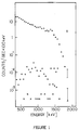
- This peak doubled in height when air with its radon replaced 50 ml of blood or urine during acquisition of a triple coincidence spectrum, as shown in Figure 1b.
- Compton scattered gammas which contribute to accidental gamma triples arriving within the 50 nsec coincident interval. This contribution is quenched by the presence of more absorbing blood or urine.
- the experimental results also guide choices of triple gamma isotopes most suitable for radioisotopic labeling of molecules.
- the solitary gamma should have an energy distinguishable from the 510 keV radon-222 gamma, so that the gamma background from radon can be most effectively rejected.
- the energy spectrum from blood obtained with the ultra-low background counter recommends an energy greater than 300 keV and preferably in the 600-1000 keV range.
- a survey of over 1000 known isotopes was made for triple gamma isotopes which satisfied the above criteria. Also a halflife of at a least a few hours is desirable to accommodate production, radioisotopic labeling chemistries and distribution to users.
- the iodine isotopes with their longer halflives and simple adduction chemistries are particularly well suited for use as radioisotopic labels for other molecules.
- the preferred embodiment of the CGD is optimized to the needs of the RIA with iodine isotopes. Quantitations will be feasible much below the level of the backgrounds of contemporary assay systems. Thus diagnostic detections of antigens (such as cancer or HIV virus indicators) will be much more sensitive.
- More generally assays of the molecules incorporating the triple gamma isotopes can be performed with much higher sensitivity. At least a thousand fold reduction in the minimal amount of radioisotope necessary for an assay will be achievable with CGD instruments, and corresponds to less than a nanocurie of triple gamma isotope. The corresponding amount of radiation is less than that from radioactive contaminants of television screens or the drinking water in areas of the Rocky Mountains.
- the binding of its conjugate iodine-126 labeled viral antigen would prepare the rod with its antibody-antigen complex for a displacement assay.
- the disassociation of the iodine-126-antigen from the antibody would be accelerated, by the presence of homologous antigen competing for the two binding sites of each antibody.
- the plastic After a chosen interval, the plastic would be withdrawn and its retained iodine-126 antibody quantitated in a CGD. From the retention, time in body fluid and calibration parameters, the concentration of the viral antigen in the body fluid would be calculated. The great value in such in situ assays would be avoidance of numerous artifacts which can accompany removal of biological specimens from their natural environment.
- a CGD will be a compact instrument, accommodate micro-samples, and be suitable for isotopes with long half lives. PET systems occupy a few rooms, are designed to accommodate people and require very short lived isotopes.
- a CGD assay will require about a nanocurie of isotope while PET imaging runs require tens of millicuries of isotope.
- the CGD uses only several scintillators while PET requires hundreds. The difference in the channels of required electronics leads to different technological challenges and design trade offs.
- the method of the invention is the improved quantitation of isotopes decaying with concurrent emission of a positron and a gamma-photon, which culminates in the production of three gammas of known energy with two being a gamma pair resulting from positron-electron annihilation.
- the improvement results from the rejection of background events which are distinguishable from the decay signature of the known triple gamma isotope in the sample, with a concomitant capacity to achieve more sensitive quantitations of the isotope. This method was made possible by the results described above in Invention Development which provide the background spectra of blood, urine and air without added radioisotopes.
- the knowledge of the background spectrum permits the choice of the triple gamma isotope(s) which both: (1) satisfy practical requirements of the radioisotopic labeling and (2) has a suitably distinguishing decay signature.
- a candidate decay of the known isotope is counted only if the instrument of the invention cannot distinguish the event from a triple gamma decay as determined by each of the three following criteria:
- the apparatus of the invention implementing the comparison of candidate events and the signature of a known triple gamma isotope is a Coincident Gamma-photon Detector (CGD) with the following general features: a sample containment transparent to the decay gammas, three or more gamma detectors well shielded from one another and intercepting gammas from the sample containment; the fast electronics including means for timing and pulse height analysis; exterior shielding; and a flow of radioisotope depleted gas serving to minimize airborne traces of contaminating radioisotopes. Automated systems of sample transport serving a CGD are prior art.
- the triple gamma isotopes can be advantageously used as labels for the sensitive quantitation of radioisotopically labeled molecules.
- Triple gamma isotopes have not previously been utilized for this role.
- the applications of the invention thus include the quantitations of molecules labeled with multiple gamma isotopes, when background count rejection is accomplished by application of the three above specified criteria.
- the chemical methods of sample preparation are prior art.
- the invention is also useful for quantitations of other isotopes decaying with production of multiple gammas of known energy, i.e. positron emitters and isotopes whose nuclei can rapidly transit through several angular momentum states with accompanying production of gamma-photons.
- the efficacy of background rejection in these cases is dependent both on the isotope and the environment provided by the containing sample.
- Figure 1a is a plot of accepted counts versus total energy of the radiation with 50 ml of normal blood measured in the sample chamber, under event acceptance conditions of: ⁇ - no coincidence; o - double coincidence; and x - triple coincidence.
- Figure 1b is a plot with triple coincidence with: ⁇ --- ⁇ air; o---o normal blood; and x - normal urine.
- Figure 2 is a diagram of signal flow in the gamma detectors.
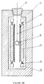
- Figure 3a is a vertical cross section of a typical detector assembly which is a preferred embodiment of the invention having four detectors.
- Figure 3b is horizontal cross section along line 2-2 of the detector assembly shown in Figure 3a.
- Figure 4 is an enlarged vertical cross section of a detector subassembly.
- Figure 5 is a cross-section of a detector subassembly consisting of scintillator, photomultiplier, photomultiplier bases and preamplifier.
- Figure 6 is a cross-sectional view of another photodetector mounting modification.
- Figure 7 is a side vertical view of the preferred embodiment of the photodetector mounting used in the gamma detector.
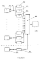
- Figure 8 is a schematic circuit diagram of the fast electronic and data acquisition circuitry.
- FIG 9 is a schematic circuit diagram of the electronics realizing a simplified energy discrimination using multiple, adjustable single channel analyzers (SCA).
- SCA single channel analyzers
- Figure 10 is a horizontal cross section of the passive/active external radiation shield.
- All components of the apparatus are prepared from highly purified materials, so as to minimize gamma producing contaminants.
- the gammas are absorbed by well-type multicrystals 1, wherein the electronic signal is amplified by low noise preamplifiers 2.
- the signals are further amplified by shaping amplifiers 3 which are also used as summators.
- the pulse heights analyzers 4, e.g. analogue-to-digital converters (ADCs) and coincidence circuitry 5 are connected via Programmable Logic Analyzer (PLA) 6 to the appropriate microprocessor 7.
- ADCs analogue-to-digital converters
- PDA Programmable Logic Analyzer
- FIGS. 3a and 3b of the detector chamber illustrate for purposes of clarity cross sections as being of square and elongated shape and having four detectors which is preferable in the practice of the invention.
- the device could also be of parallelpiped, cylindrical or round construction with a minimum of three equally spaced and separated detectors.
- each of four scintillators 10 is coupled through two solid state photodetectors 12 to low noise preamplifiers 13.
- the radioactive sample is in a container 8 made from low atomic number materials. Container 8 is sealed to prevent radioactive dust from contaminating the detector interior.
- the container is suspended on very high purity, quartz rod 14. The entire assembly is purged from a bottom vent with clean helium gas to eliminate radon and radioactive dusts prior to initiation of counting.
- the small aperture for sample insertion is blocked by a plug 15 after purging.
- the sample is positioned within a cylindrical low atomic number metal, e.g. aluminum foil 9.
- This foil can be simply replaced when an increasing background count indicates contamination.
- the positrons are predominantly annihilated within the sample and volume circumscribed by the cylinder. Count loses which would often accompany positron annihilation on a scintillator are thus avoided.
- Due to the low atomic number of the said container and the said foil shield they are transparent to the gammas of energy less than 300 keV. The gammas are absorbed in the scintillation crystals producing photoelectrons and a resultant low energy photon shower.
- the high density septa 12 are between crystals, to minimize back-scatter of photoelectrons and photons between detectors.
- the septa have a density preferably greater than 5 g/cc, such as obtained with bismuth, lead, thallium, mercury, gold, copper, tungsten, tantalum, and the like and alloys thereof.
- the entire detector subassembly is shielded from external radiation by a low radioactive background passive shield 11, constructed to serve as both Faraday cage blocking external electromagnetic pulse noise and external radiation (electrons/photons/neutrons) shield.
- a scintillator 16 is covered by diffusively reflecting thin layer 17 and coupled to a photomultiplier 18. This reflecting layer limits loses of low energy photons from the photodetector assembly.
- the photomultiplier base 19 and the low noise fast preamplifier are also present.
- the photodetectors are optically coupled to the scintillators are preferably narrow gap photodetectors such as mercuric iodide, high purity germanium, and the like.
- the photomultiplier base 19 and the low noise, fast preamplifier 20 are also presented.
- solid state photodetectors are used, i.e.
- the scintillators are optically coupled to preferably narrow gap semiconducting photodetectors made of silicon, mercuric iodide, high purity germanium, and the like.
- the scintillator 16 preferably has a density greater than 4 g/cc and an atomic number greater than 50.
- Particularly preferred are scintillators with a density greater than 10 g/cc.
- FIGs 5-7 there are illustrated various mounting techniques for the fabrication of the photodetectors/scintillator.
- the scintillator 22 is mounted to a single solid state photodetector 21 using a fan-shaped optically transparent coupling 23.
- the side of the assembly which is not adjacent to the solid state photodetector 21 is suitably coated with a diffusing/reflecting layer 24.
- the dashed line represents in Figure 5 the division between the non-glass coupler 23 and the scintillator crystal 22, whereas in Figure 6 there is no dash separation line shown, as the scintillator 26 is formed and shaped to provide the desired "truncated" effect to the end mounts for these particular photodetector/scintillators.
- FIG 7 there is shown another alternate construction which is of the preferred arrangement wherein two solid state photodetectors 28 are joined and connected to the scintillator 29 having tapered ends (like those shown in Figure 6.
- said scintillator 29 is further provided with a diffusive reflector 30.
- FIG 8 there is shown a schematic circuit diagram of the multichannel electronics and data acquisition circuitry.
- the signal from the scintillating detector 31 is amplified by a fast preamplifier 32 and shaped by a shaping amplifier 33.
- the pulse amplitude is then analyzed by a pulse height analyzer 34 and triggers a NIM (or TTL) level pulse in a fast threshold device (single-shot) 35.
- the output from four single shots is feeding coincidence circuitry 36. All pulse high analyzers 34 and coincidence circuit 36 are communicating with a dedicated microprocessor 37 via eight bites bus line 38. For simplicity only two channels of electronics are depicted whereas in the real device three or more channels will be used.
- the detectors 31 detect ionizing radiation and output electrical signals. Since the signals output by the detectors 31 are typically low-level signals, they are received by low-noise preamplifiers 32, generally two preamplifiers 32, per channel, which amplify the low-level signals without appreciably degrading the signal-to-noise ratio of the low-level signals.
- the signals developed by the preamplifiers 32 are received by amplifiers 33, generally one amplifier 33 per channel, which add, amplify and appropriately shape the signals for output to a pulse height analyzer 34.
- the pulse height analyzer 34 analyzes the signal output by the amplifier 33 to determine the number of occurrences of pulses that fall within a specified amplitude range and outputs a signal to coincidence circuitry 35.
- each single channel pulse height analyzer analyzes the amplified and shaped signal output of its respective amplifier 33 to determine the number of occurrences of pulses that fall within its respective specified amplitude range.
- the coincidence circuitry 35 outputs a pulse to a Programmable Logic Analyzer 36 when it receives a specified number of appropriate pulses within an assigned time interval from the pulse height analyzer 34.
- the Programmable Logic Analyzer 36 analyzes the pulses received form the coincidence circuitry 35 and outputs a signal appropriate for processing by a microprocessor 37.
- the micro-processor 37 receives the signal from the Programmable Logic Analyzer 36, processes the signal and determines whether to register the analyzed event as a valid count.
- FIG. 8 is a block diagram of the electronic circuitry of the present invention which is conventional in design and construction, a more detailed description is deemed unnecessary. In this regard, it should also be understood that other circuit designs may be employed by skilled artisans in lieu of the circuit design shown herein without departing from the scope of the present invention.
- FIG 9 an alternate circuit design is shown having an additional detector with a corresponding preamplifier, amplifier and single channel pulse height analyzer operated in a threshold mode.
- This detector-analyzer arrangement is mounted externally of the passive shield and outputs a pulse/signal to the programmable logic analyzer which is used to reject background radiation, such as cosmic Rays.
- the Programmable Logic Analyzer 46 analyzes the coincidence and value of the output of twelve (much less expensive) single channel pulse height analyzers, and the anticoincidence of the thirteen single pulse height channel analyzer, and then, if desired, may update the count rate of a suitable counter (now shown in Figure 10) connected to the Programmable Logic Analyzer.
- a suitable counter now shown in Figure 10
- FIG. 9 there is shown a schematic circuit diagram of the preferred embodiment of the multichannel electronics and data acquisition circuitry, specifically set to detect the iodine-126.
- the signal from the scintillating detector 39 is amplified by a fast preamplifier 40 and shaped by a shaping amplifier 41. It is then split and looked upon by three single channel analyzers (SCAl, SCA2 and SCA3).
- the SCAl 42 is set for energy of 511 keV ⁇ 10%.
- SCA2 43 is set for an energy of 600 keV ⁇ 10% and SCA3 44 is set for 1.1 meV ⁇ 10%. If the detected energy is within the SCA range, a short duration TTL level pulse is generated.
- the output from four scintillation counters is processed by twelve SCA and then analyzed by a Programmable Logic Analyzer (PLA) 46.
- PPA Programmable Logic Analyzer
- the output of the plastic scintillator 45 is appropriately amplified/shaped and is analyzed by SCA 47 operated in the threshold mode and can be used to reject cosmic rays.
- the PLA looks into a coincidence and value of output of twelve SCAs and anticoincidence of thirteen SCAs and then updates the count-rate at counter 48.
- FIG 10 there is shown an optional shielding arrangement which may be employed in the practice of the invention.
- a scintillation counter assembly 49 formed in the same manner as those hereinbefore described, such as shown in Figures 1-6, and said assembly; is disposed inside a plastic anticoincidence scintillator 50.
- Very high purity oxygen free copper (OFHC) is used as an internal part of passive shield 51 and operates to stop all photons with E ⁇ 100 keV, including K-edge photons from lead.
- a further thick ring of high purity lead 52 stops the majority of high energy photons (E ⁇ 100 keV) as well as all charged particles with E ⁇ 10 meV.
- an external ring of boron loaded plastic 53 is used to stop the majority of low energy neutrons.
- a cylindrical shape is shown, other geometrical shapes may be employed for construction of the device, such as cylindrical, square or rectangular, parallelpiped, and the like.
Landscapes
- Physics & Mathematics (AREA)
- Health & Medical Sciences (AREA)
- Life Sciences & Earth Sciences (AREA)
- General Physics & Mathematics (AREA)
- High Energy & Nuclear Physics (AREA)
- Molecular Biology (AREA)
- Spectroscopy & Molecular Physics (AREA)
- Measurement Of Radiation (AREA)
- Analysing Materials By The Use Of Radiation (AREA)
Applications Claiming Priority (2)
| Application Number | Priority Date | Filing Date | Title |
|---|---|---|---|
| US07/478,945 US5083026A (en) | 1990-02-12 | 1990-02-12 | Method, apparatus and applications of the quantitation of multiple gamma-photon producing isotopes with increased sensitivity |
| US478945 | 1990-12-02 |
Publications (3)
| Publication Number | Publication Date |
|---|---|
| EP0490108A2 true EP0490108A2 (de) | 1992-06-17 |
| EP0490108A3 EP0490108A3 (en) | 1993-02-24 |
| EP0490108B1 EP0490108B1 (de) | 1997-07-23 |
Family
ID=23902035
Family Applications (1)
| Application Number | Title | Priority Date | Filing Date |
|---|---|---|---|
| EP91119367A Expired - Lifetime EP0490108B1 (de) | 1990-02-12 | 1991-11-13 | Verfahren, Vorrichtung und Anwendungen der quantitativen Bestimmung von mehrere Gammaphotonen aussendenden Isotopen mit erhöhter Empfindlichkeit |
Country Status (4)
| Country | Link |
|---|---|
| US (1) | US5083026A (de) |
| EP (1) | EP0490108B1 (de) |
| DE (1) | DE69126954T2 (de) |
| ES (1) | ES2106758T3 (de) |
Cited By (4)
| Publication number | Priority date | Publication date | Assignee | Title |
|---|---|---|---|---|
| EP0667539A1 (de) * | 1994-02-03 | 1995-08-16 | Nuclear Engineering, Ltd. | Verfahren zur Messung der Gammastrahlungs von Radionukliden, insbesondere für Primärewasser von einer Kernreaktor |
| GB2400909A (en) * | 2003-03-12 | 2004-10-27 | Gen Electric | Oil well logging sensor |
| WO2005116691A1 (en) * | 2004-05-24 | 2005-12-08 | Symetrica Limited | Gamma ray detectors |
| RU2296352C1 (ru) * | 2005-11-22 | 2007-03-27 | Закрытое акционерное общество "ИНТРА" | Сцинтилляционное детектирующее устройство |
Families Citing this family (23)
| Publication number | Priority date | Publication date | Assignee | Title |
|---|---|---|---|---|
| US5532122A (en) * | 1993-10-12 | 1996-07-02 | Biotraces, Inc. | Quantitation of gamma and x-ray emitting isotopes |
| US5854084A (en) | 1996-07-12 | 1998-12-29 | Biotraces, Inc. | Enhanced chromatography using multiphoton detection |
| EP1019750A1 (de) * | 1995-12-28 | 2000-07-19 | Canberra Industries, Inc. | Wahre übereinstimmungs-sunnenkorrektur für strahlungsdetektoren |
| DE19854430A1 (de) * | 1998-11-25 | 2000-06-08 | Esm Eberline Instr Strahlen Un | Verfahren und Einrichtung zum Messen der radioaktiven Kontamination eines Meßobjektes |
| GB2381862A (en) * | 2001-11-10 | 2003-05-14 | Schlumberger Holdings | Fluid density measurement |
| KR100478533B1 (ko) * | 2002-07-30 | 2005-03-28 | 한국수력원자력 주식회사 | 레이저를 이용한 탈륨 동위원소 분리방법 |
| US6924487B2 (en) * | 2002-10-01 | 2005-08-02 | Constellation Technology Corporation | Neutron detector |
| TWI272934B (en) * | 2004-04-02 | 2007-02-11 | Nat Health Research Institutes | A device and method for digitizing pet radiation events |
| US7820977B2 (en) * | 2005-02-04 | 2010-10-26 | Steve Beer | Methods and apparatus for improved gamma spectra generation |
| US8173970B2 (en) * | 2005-02-04 | 2012-05-08 | Dan Inbar | Detection of nuclear materials |
| US20110101230A1 (en) * | 2005-02-04 | 2011-05-05 | Dan Inbar | Advanced SNM Detector |
| US7847260B2 (en) | 2005-02-04 | 2010-12-07 | Dan Inbar | Nuclear threat detection |
| GB0622956D0 (en) * | 2006-11-17 | 2006-12-27 | Univ Birmingham | Molecular detection system |
| BRPI1016011A2 (pt) * | 2009-06-29 | 2016-04-26 | Baker Hugues Inc | uso de cristais sólidos como tubos de luz contínua para convergir luz para janela pmt. |
| WO2012135725A2 (en) * | 2011-03-30 | 2012-10-04 | The Board Of Trustees Of The Leland Stanford Junior University | Methods and systems for increasing the sensitivity of simultaneous multi-isotope positron emission tomography |
| US9320478B2 (en) | 2011-04-29 | 2016-04-26 | The Board Of Trustees Of The Leland Stanford Junior University | Dual-isotope position emitting tomography for disease evaluation |
| US9310491B2 (en) * | 2012-09-27 | 2016-04-12 | Schlumberger Technology Corporation | Scintillator with tapered geometry for radiation detectors |
| US20140325828A1 (en) * | 2013-05-01 | 2014-11-06 | Schlumberger Technology Corporation | Method of making a well-logging radiation detector |
| FR3010534B1 (fr) * | 2013-09-06 | 2015-10-09 | Commissariat Energie Atomique | Systeme et procede de detection de rayonnements neutron, gamma et muon avec des scintillateurs plastiques contigus |
| CN106405615A (zh) * | 2016-08-26 | 2017-02-15 | 北京放射性核素实验室 | 一种高灵敏探测放射性气体核素活度的装置及方法 |
| CN109557575A (zh) * | 2018-12-17 | 2019-04-02 | 中国原子能科学研究院 | 一种中子多重性测量装置及其使用方法 |
| CN109633732A (zh) * | 2019-01-09 | 2019-04-16 | 中国原子能科学研究院 | 一种测量装置 |
| CN110501740B (zh) * | 2019-08-23 | 2024-12-03 | 南京核安核能科技有限公司 | 一种本底数字化反康反宇宙射线谱仪HPGe探测器探测方法 |
Family Cites Families (6)
| Publication number | Priority date | Publication date | Assignee | Title |
|---|---|---|---|---|
| US3979593A (en) * | 1973-03-22 | 1976-09-07 | Australian Atomic Energy Commission | Detector for measuring a radioisotope tracer gas |
| US4395634A (en) * | 1979-12-21 | 1983-07-26 | General Mining Union Corporation Limited | Radiometric methods and means |
| US4495420A (en) * | 1982-04-28 | 1985-01-22 | Univerzita Komenskeho | Multilayer scintillation chamber for the simultaneous measurement of radioactive samples |
| US4833326A (en) * | 1985-04-08 | 1989-05-23 | Packard Instrument Company, Inc. | Liquid scintillation measurement system with active guard shield |
| US4864140A (en) * | 1987-08-31 | 1989-09-05 | The University Of Michigan | Coincidence detection system for positron emission tomography |
| US4931646A (en) * | 1989-03-17 | 1990-06-05 | The United States Of America As Represented By The Secretary Of The Army | Remote multichannel coincident nuclear detector and characterization system |
-
1990
- 1990-02-12 US US07/478,945 patent/US5083026A/en not_active Expired - Lifetime
-
1991
- 1991-11-13 DE DE69126954T patent/DE69126954T2/de not_active Expired - Fee Related
- 1991-11-13 EP EP91119367A patent/EP0490108B1/de not_active Expired - Lifetime
- 1991-11-13 ES ES91119367T patent/ES2106758T3/es not_active Expired - Lifetime
Cited By (5)
| Publication number | Priority date | Publication date | Assignee | Title |
|---|---|---|---|---|
| EP0667539A1 (de) * | 1994-02-03 | 1995-08-16 | Nuclear Engineering, Ltd. | Verfahren zur Messung der Gammastrahlungs von Radionukliden, insbesondere für Primärewasser von einer Kernreaktor |
| GB2400909A (en) * | 2003-03-12 | 2004-10-27 | Gen Electric | Oil well logging sensor |
| WO2005116691A1 (en) * | 2004-05-24 | 2005-12-08 | Symetrica Limited | Gamma ray detectors |
| US7547887B2 (en) | 2004-05-24 | 2009-06-16 | Symetrica Limited | Gamma ray spectrometers |
| RU2296352C1 (ru) * | 2005-11-22 | 2007-03-27 | Закрытое акционерное общество "ИНТРА" | Сцинтилляционное детектирующее устройство |
Also Published As
| Publication number | Publication date |
|---|---|
| DE69126954T2 (de) | 1998-02-12 |
| EP0490108B1 (de) | 1997-07-23 |
| EP0490108A3 (en) | 1993-02-24 |
| DE69126954D1 (de) | 1997-09-04 |
| ES2106758T3 (es) | 1997-11-16 |
| US5083026A (en) | 1992-01-21 |
Similar Documents
| Publication | Publication Date | Title |
|---|---|---|
| EP0490108B1 (de) | Verfahren, Vorrichtung und Anwendungen der quantitativen Bestimmung von mehrere Gammaphotonen aussendenden Isotopen mit erhöhter Empfindlichkeit | |
| US5866907A (en) | Ultralow background multiple photon detector | |
| Prekeges | Nuclear Medicine Instrumentation (book):. | |
| US5665971A (en) | Radiation detection and tomography | |
| AU700518B2 (en) | Ultralow background multiple photon detector | |
| US8039810B2 (en) | Scintillation-based continuous monitor for beta-emitting radionuclides in a liquid medium | |
| Landsberger et al. | Compton suppression neutron activation analysis: past, present and future | |
| RU2143711C1 (ru) | Детектор для регистрации ионизирующих излучений | |
| Mauerhofer et al. | A Compton suppression spectrometer for neutron activation analysis | |
| Laurec et al. | A new low background gamma spectrometer equipped with an anti-cosmic device | |
| US3246151A (en) | Low background beta-ray scintillation spectrometer | |
| Pommé et al. | Standardisation of 125I using seven techniques for radioactivity measurement | |
| Steinberg et al. | [20] The measurement of radioisotopes | |
| Hentig et al. | Records in ultra low radioactivity measurements with neutron activation analysis | |
| Palazzolo et al. | A beta spectrometer for monitoring environmental matrices | |
| Kaihola | Glass vial background reduction in liquid scintillation counting | |
| Ellett et al. | A total absorption gamma ray spectrometer combining sodium iodide and plastic scintillators | |
| Steinberg | Counting methods for the assay of radioactive samples | |
| Chotoo et al. | Evaluation of polymer-coated CsI: Tl as an alpha/beta pulse shape discriminating flow cell | |
| WO1995012825A1 (en) | Flow cell for use in a flow scintillation analyzer | |
| RU2217777C2 (ru) | Устройство для определения концентрации радиоактивных веществ | |
| KELLER | Applied radiation measurements | |
| Crosbie | Chapter IV Ionization Methods of Counting Radio-Isotopes | |
| Khater | Radiation detection methods | |
| Trueblood et al. | DIRECTIONAL CORRELATION AND INTENSITY STUDIES OF ELECTROMAGNETIC TRANSITIONS IN $ sup 181$ Ta. |
Legal Events
| Date | Code | Title | Description |
|---|---|---|---|
| PUAI | Public reference made under article 153(3) epc to a published international application that has entered the european phase |
Free format text: ORIGINAL CODE: 0009012 |
|
| AK | Designated contracting states |
Kind code of ref document: A2 Designated state(s): DE ES FR GB IT |
|
| PUAL | Search report despatched |
Free format text: ORIGINAL CODE: 0009013 |
|
| AK | Designated contracting states |
Kind code of ref document: A3 Designated state(s): DE ES FR GB IT |
|
| 17P | Request for examination filed |
Effective date: 19931109 |
|
| 17Q | First examination report despatched |
Effective date: 19950111 |
|
| GRAG | Despatch of communication of intention to grant |
Free format text: ORIGINAL CODE: EPIDOS AGRA |
|
| RAP1 | Party data changed (applicant data changed or rights of an application transferred) |
Owner name: BIOTRACES, INC. |
|
| GRAH | Despatch of communication of intention to grant a patent |
Free format text: ORIGINAL CODE: EPIDOS IGRA |
|
| GRAH | Despatch of communication of intention to grant a patent |
Free format text: ORIGINAL CODE: EPIDOS IGRA |
|
| GRAA | (expected) grant |
Free format text: ORIGINAL CODE: 0009210 |
|
| AK | Designated contracting states |
Kind code of ref document: B1 Designated state(s): DE ES FR GB IT |
|
| REF | Corresponds to: |
Ref document number: 69126954 Country of ref document: DE Date of ref document: 19970904 |
|
| ITF | It: translation for a ep patent filed | ||
| ET | Fr: translation filed | ||
| REG | Reference to a national code |
Ref country code: ES Ref legal event code: FG2A Ref document number: 2106758 Country of ref document: ES Kind code of ref document: T3 |
|
| PLBE | No opposition filed within time limit |
Free format text: ORIGINAL CODE: 0009261 |
|
| STAA | Information on the status of an ep patent application or granted ep patent |
Free format text: STATUS: NO OPPOSITION FILED WITHIN TIME LIMIT |
|
| 26N | No opposition filed | ||
| PGFP | Annual fee paid to national office [announced via postgrant information from national office to epo] |
Ref country code: ES Payment date: 19981123 Year of fee payment: 8 |
|
| PG25 | Lapsed in a contracting state [announced via postgrant information from national office to epo] |
Ref country code: ES Free format text: LAPSE BECAUSE OF NON-PAYMENT OF DUE FEES Effective date: 19991114 |
|
| PGFP | Annual fee paid to national office [announced via postgrant information from national office to epo] |
Ref country code: GB Payment date: 20010131 Year of fee payment: 10 |
|
| PG25 | Lapsed in a contracting state [announced via postgrant information from national office to epo] |
Ref country code: GB Free format text: LAPSE BECAUSE OF NON-PAYMENT OF DUE FEES Effective date: 20011113 |
|
| PGFP | Annual fee paid to national office [announced via postgrant information from national office to epo] |
Ref country code: DE Payment date: 20011210 Year of fee payment: 11 |
|
| PGFP | Annual fee paid to national office [announced via postgrant information from national office to epo] |
Ref country code: FR Payment date: 20011212 Year of fee payment: 11 |
|
| REG | Reference to a national code |
Ref country code: GB Ref legal event code: IF02 |
|
| PG25 | Lapsed in a contracting state [announced via postgrant information from national office to epo] |
Ref country code: DE Free format text: LAPSE BECAUSE OF NON-PAYMENT OF DUE FEES Effective date: 20030603 |
|
| PG25 | Lapsed in a contracting state [announced via postgrant information from national office to epo] |
Ref country code: FR Free format text: LAPSE BECAUSE OF NON-PAYMENT OF DUE FEES Effective date: 20030731 |
|
| REG | Reference to a national code |
Ref country code: FR Ref legal event code: ST |
|
| REG | Reference to a national code |
Ref country code: ES Ref legal event code: FD2A Effective date: 20001214 |
|
| PG25 | Lapsed in a contracting state [announced via postgrant information from national office to epo] |
Ref country code: IT Free format text: LAPSE BECAUSE OF NON-PAYMENT OF DUE FEES;WARNING: LAPSES OF ITALIAN PATENTS WITH EFFECTIVE DATE BEFORE 2007 MAY HAVE OCCURRED AT ANY TIME BEFORE 2007. THE CORRECT EFFECTIVE DATE MAY BE DIFFERENT FROM THE ONE RECORDED. Effective date: 20051113 |