EP0490261A2 - Système de facsimilé - Google Patents
Système de facsimilé Download PDFInfo
- Publication number
- EP0490261A2 EP0490261A2 EP91120853A EP91120853A EP0490261A2 EP 0490261 A2 EP0490261 A2 EP 0490261A2 EP 91120853 A EP91120853 A EP 91120853A EP 91120853 A EP91120853 A EP 91120853A EP 0490261 A2 EP0490261 A2 EP 0490261A2
- Authority
- EP
- European Patent Office
- Prior art keywords
- facsimile
- telephone
- pseudo
- signal
- call request
- Prior art date
- Legal status (The legal status is an assumption and is not a legal conclusion. Google has not performed a legal analysis and makes no representation as to the accuracy of the status listed.)
- Granted
Links
Images


Classifications
-
- H—ELECTRICITY
- H04—ELECTRIC COMMUNICATION TECHNIQUE
- H04N—PICTORIAL COMMUNICATION, e.g. TELEVISION
- H04N1/00—Scanning, transmission or reproduction of documents or the like, e.g. facsimile transmission; Details thereof
- H04N1/32—Circuits or arrangements for control or supervision between transmitter and receiver or between image input and image output device, e.g. between a still-image camera and its memory or between a still-image camera and a printer device
- H04N1/327—Initiating, continuing or ending a single-mode communication; Handshaking therefor
- H04N1/32704—Establishing a communication with one of a facsimile and another telecommunication apparatus sharing a single line
- H04N1/32706—Type of the other apparatus
- H04N1/32708—Telephone
-
- H—ELECTRICITY
- H04—ELECTRIC COMMUNICATION TECHNIQUE
- H04N—PICTORIAL COMMUNICATION, e.g. TELEVISION
- H04N1/00—Scanning, transmission or reproduction of documents or the like, e.g. facsimile transmission; Details thereof
- H04N1/32—Circuits or arrangements for control or supervision between transmitter and receiver or between image input and image output device, e.g. between a still-image camera and its memory or between a still-image camera and a printer device
- H04N1/327—Initiating, continuing or ending a single-mode communication; Handshaking therefor
- H04N1/32704—Establishing a communication with one of a facsimile and another telecommunication apparatus sharing a single line
- H04N1/32715—Detecting
- H04N1/32719—Detecting a facsimile calling signal, e.g. CNG
-
- H—ELECTRICITY
- H04—ELECTRIC COMMUNICATION TECHNIQUE
- H04N—PICTORIAL COMMUNICATION, e.g. TELEVISION
- H04N1/00—Scanning, transmission or reproduction of documents or the like, e.g. facsimile transmission; Details thereof
- H04N1/32—Circuits or arrangements for control or supervision between transmitter and receiver or between image input and image output device, e.g. between a still-image camera and its memory or between a still-image camera and a printer device
- H04N1/327—Initiating, continuing or ending a single-mode communication; Handshaking therefor
- H04N1/32704—Establishing a communication with one of a facsimile and another telecommunication apparatus sharing a single line
- H04N1/32715—Detecting
- H04N1/32726—Detecting signals other than facsimile protocol signals, e.g. DTMF signals
-
- H—ELECTRICITY
- H04—ELECTRIC COMMUNICATION TECHNIQUE
- H04N—PICTORIAL COMMUNICATION, e.g. TELEVISION
- H04N1/00—Scanning, transmission or reproduction of documents or the like, e.g. facsimile transmission; Details thereof
- H04N1/32—Circuits or arrangements for control or supervision between transmitter and receiver or between image input and image output device, e.g. between a still-image camera and its memory or between a still-image camera and a printer device
- H04N1/327—Initiating, continuing or ending a single-mode communication; Handshaking therefor
- H04N1/32704—Establishing a communication with one of a facsimile and another telecommunication apparatus sharing a single line
- H04N1/32715—Detecting
- H04N1/32728—Detecting an off-hook condition
-
- H—ELECTRICITY
- H04—ELECTRIC COMMUNICATION TECHNIQUE
- H04N—PICTORIAL COMMUNICATION, e.g. TELEVISION
- H04N1/00—Scanning, transmission or reproduction of documents or the like, e.g. facsimile transmission; Details thereof
- H04N1/32—Circuits or arrangements for control or supervision between transmitter and receiver or between image input and image output device, e.g. between a still-image camera and its memory or between a still-image camera and a printer device
- H04N1/327—Initiating, continuing or ending a single-mode communication; Handshaking therefor
- H04N1/32704—Establishing a communication with one of a facsimile and another telecommunication apparatus sharing a single line
- H04N1/32739—Generating signals
- H04N1/32741—Generating ringing or calling signals or tones
Definitions
- the present invention relates to a facsimile system including a facsimile apparatus and a telephone apparatus, in which the telephone apparatus is furnished externally with respect to the facsimile apparatus and shares one telephone line with the facsimile apparatus.
- a facsimile apparatus is developed to be reduced in its size and weight nowadays. Especially, as a facsimile apparatus of a low cost and low grade model for the ordinary household use, such a facsimile apparatus as can be externally connected to the conventional telephone apparatus and has only a basic facsimile function, is being well developed.
- the facsimile apparatus shares one telephone line with the telephone apparatus.
- facsimile apparatus when the call is requested to the relevant telephone number, the operator firstly hears and checks the sound outputted from the speaker of the handset of the telephone apparatus by himself, and manually starts either the facsimile receiving operation by use of the facsimile apparatus (facsimile receiving mode) or the conversation by use of the telephone apparatus (conversation mode).
- the inventors of the present invention know a developed type of the facsimile apparatus having a TEL/FAX automatically switching function, in which the facsimile apparatus is adapted such that the conversation mode is firstly set when the call arrives, that is to say, the telephone line is firstly automatically connected to the telephone apparatus through the facsimile apparatus so as to ring the telephone apparatus for the predetermined times. Then, the facsimile receiving mode is subsequently set, that is to say, the telephone line is automatically connected to the facsimile apparatus so that it can start the facsimile receiving operation, if the operator does not respond to this ringing sound by picking up the handset (OFF hook) during the conversation mode.
- the operator can not establish the conversation of the telephone apparatus any more, since the telephone line is not connected to the telephone apparatus in this facsimile receiving mode, which is a problem in the practical use of this type of facsimile system.
- this facsimile apparatus judges whether the calling station is a facsimile apparatus or a telephone apparatus by checking the CNG (Calling Tone) signal, which is supposed to be generated and transmitted from the facsimile apparatus. If it is found that the calling station is a telephone apparatus, the facsimile apparatus generates a pseudo-ringing sound by an exclusive pseudo-ringing device provided in the facsimile apparatus so as to ring up the operator at the site of the facsimile apparatus.
- CNG Click Tone
- the sound can be generated only at the site of the facsimile apparatus i.e. not at the site of the telephone apparatus.
- the telephone apparatus is located near the facsimile apparatus, the sound generated by the facsimile apparatus can be heard at the site of the telephone apparatus as well by the operator without any problem.
- the telephone apparatus is located remote from the facsimile apparatus, the pseudo-ringing sound can not be heard by the operator who is in the vicinity of the telephone apparatus, which is the problem in this type of facsimile apparatus. Since the telephone apparatus is often located to such a remote place especially in case of the cord-less telephone, which is being well developed nowadays, this problem is quite serious in a practical sense.
- the facsimile may be provided with many sophisticated functions such as a telephone line holding function, and a call requesting function to call the telephone apparatus, which is externally furnished with respect to the facsimile apparatus, just in the same manner as the calling station calls the telephone apparatus via the telephone exchange through the telephone line.
- this facsimile apparatus can make the telephone apparatus ringing even when the call request signal from the telephone exchange through the telephone line is not inputted to the facsimile apparatus.
- this facsimile apparatus is adapted to ring the external telephone apparatus whenever it is necessary in the TEL/FAX automatically switching operation i.e. to make a real ringing sound of the telephone apparatus, in place of the above mentioned pseudo-ringing sound generated by the facsimile apparatus.
- the operator can hear this real ringing-sound at the site of the telephone apparatus even if it is located remote from the facsimile apparatus, without the above mentioned problem.
- a facsimile system including: a telephone apparatus; a facsimile receiving device for detecting a CNG (Calling Tone) signal, which follows a call request signal from a telephone exchange, on a telephone line, and receiving a facsimile data through the telephone line if the CNG signal is detected; a switching device for selectively connecting the telephone line to either the facsimile receiving device or the telephone apparatus; a device for controlling the switching device such that the switching device connects the telephone line to the telephone apparatus if the CNG signal is not detected by the facsimile receiving device while the telephone line is connected to the facsimile receiving device; and a device for generating a control signal if the CNG signal is not detected by the facsimile receiving device.
- CNG Calling Tone
- the facsimile system also includes a pseudo-call requesting device connected to the generating device and the telephone apparatus for outputting a pseudo-call request signal, which is substantially same as the call request signal from the telephone exchange, to the telephone apparatus to make the telephone apparatus ringing when the control signal is inputted from the generating device.
- the telephone line when there is a call to the present facsimile system, the telephone line is connected as the original state, by the switching device under the control of the control device, to the telephone apparatus (conversation mode) for the predetermined number of times of the arrived call request signal, so as to make the telephone apparatus ringing during the corresponding period. Then, if the operator does not respond to the telephone apparatus, the telephone line is connected, by the switching device under the control of the control device, to the facsimile receiving device (facsimile receiving mode). Alternatively, the telephone line may be connected as the original state, by the switching device under the control of the control device, to the facsimile receiving device.
- the facsimile receiving device when the telephone line is connected to the facsimile receiving device, the facsimile receiving device responds to the pertinent call request signal from the telephone exchange. Accordingly, the call request signal is ceased, and the communication on the telephone line between the facsimile system and the calling station is established. Then the facsimile receiving device checks if there is a CNG signal on the telephone line.
- the facsimile receiving device If the facsimile receiving device detects the CNG signal, the facsimile receiving device judges that the calling station is the facsimile apparatus for requesting the facsimile communication. Thus, the facsimile receiving operation is started by the facsimile receiving device.
- the facsimile receiving device judges that the calling station is a telephone apparatus for requesting the conversation (i.e. voice communication). Then, the generating device generates and outputs the control signal, such as a DTMF (Dual Tone Multi-Frequency) signal, to the pseudo-call requesting device. Then, the pseudo-call requesting device generates and outputs the pseudo-call request signal, which is substantially same as the real call request signal from the telephone exchange.
- the control signal such as a DTMF (Dual Tone Multi-Frequency) signal
- the telephone apparatus can be made ringing by this pseudo-call request signal, in the pertinent TEL/FAX automatic switching operation, just in the same manner as when the real call request signal is inputted to the telephone apparatus.
- the operator in the vicinity of the telephone apparatus can still hear the real ringing sound of the telephone apparatus in this case and can establish the conversation on the telephone apparatus without any problem.
- the facsimile receiving device, the switching device, the control device and the generating device are provided in one unit of a facsimile apparatus.
- the pseudo-call requesting device can be equipped between thus constructed facsimile apparatus and the telephone apparatus.
- the construction of the facsimile system becomes quite advantageous in that a facsimile apparatus quite similar in its specification to that of the rather simple facsimile apparatus in the aforementioned related art for the household use, can be employed as the facsimile apparatus, while the above mentioned very convenient TEL/FAX automatic switching operation can be realized with such a simple facsimile apparatus and a conventional type telephone apparatus, just by equipping the pseudo-call requesting device between them, with a benefit of making the total cost quite low.
- Fig. 1 which is composed of Fig. 1A and Fig. 1B, shows a block diagram of a facsimile system as one embodiment of the present invention.
- the facsimile system includes a pseudo-call requesting apparatus 1, a facsimile apparatus 2 and a telephone apparatus 3.
- the pseudo-call requesting apparatus 1 is connected to a telephone line L at its terminal A .
- the pseudo-call requesting apparatus 1 is also connected to the facsimile apparatus 2 and to the telephone apparatus 3. More particularly, a terminal B of the pseudo-call requesting apparatus 1 is connected to a terminal BB of the facsimile apparatus 2, and a terminal C of the pseudo-call requesting apparatus 1 is connected to a terminal CC of the facsimile apparatus 2, while a terminal D of the pseudo-call requesting apparatus 1, is connected to the telephone apparatus 3.
- the telephone apparatus 3 is externally furnished with respect to the facsimile apparatus 2, has a handset 3a, and is adapted to ring when it is dialed i.e. the call request signal, which is normally transmitted from the telephone exchange through the telephone line L in the normal telephone operation, is inputted thereto.
- the telephone apparatus 3 shares the telephone line L with the facsimile apparatus 3 under the control of a line control unit 10 of the facsimile apparatus 2.
- the facsimile apparatus 2 is provided with a switch SW3, a facsimile receiving unit 9 and the line control circuit 10, such that the switch SW3 is adapted to be switched so as to connect the telephone line L via the terminals A , B and BB , to either the facsimile receiving unit 9 or the telephone apparatus 3 further via the terminals CC , C and D .
- the facsimile apparatus 2 has an automatic TEL/FAX switching function, in which the conversation (i.e. voice communication) mode and the facsimile receiving mode can be automatically switched over to each other. More particularly, when the calling station dials the facsimile apparatus 2, the facsimile apparatus 2 allows the pertinent call request signal from the telephone exchange to pass therethrough to the telephone apparatus 3 via the switch SW3 for a predetermined time period, so as to ring the telephone apparatus 3 for predetermined times, and then the facsimile apparatus 2 switches the switch SW3 to the side of the facsimile receiving unit 9 so as to check if there is the CNG signal on the telephone line L , that is to say, the calling station is a facsimile apparatus or not.
- the facsimile apparatus 2 switches the switch SW3 to the side of the facsimile receiving unit 9 so as to check if there is the CNG signal on the telephone line L , that is to say, the calling station is a facsimile apparatus or not.
- the facsimile apparatus 2 may be provided with a mode selection switch of a operation panel on the main body of the facsimile apparatus 2, to select either the above mentioned TEL/FAX automatically switching mode or a manual switching mode, in which the operator can manually select the facsimile receiving operation or the telephone operation after checking the CNG signal sound by the handset 3a.
- the facsimile apparatus 2 is also provided with a pseudo-ringing circuit 11, a hook detection circuit 12 and a DTMF (Dual Tone Multi-Frequency) signal generating circuit 13.
- the pseudo-ringing circuit 11 generates a pseudo-ringing sound at the site of the facsimile apparatus 2 in order to ring up again the operator after the operation mode is once automatically switched over to the facsimile receiving mode and yet it is found that the voice communication is actually requested by the telephone apparatus of the calling station by checking the CNG signal.
- the hook detection circuit 12 is adapted to detect the ON/OFF hook condition of the handset 3a of the telephone apparatus 3 via the terminals D , C and CC .
- the DTMF signal generating circuit 13 is adapted to generate the DTMF signal to the pseudo-call requesting apparatus 1 via the terminals BB and B , so as to start and stop the operation of the pseudo-call requesting apparatus 1.
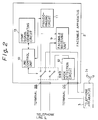
- the facsimile apparatus 2 is adapted to be operative too in such a configuration that the facsimile apparatus 2 is directly connected to the telephone line L and to the telephone apparatus 3 (without the pseudo-call requesting apparatus 1 therebetween), since the facsimile apparatus 2 can establish either the facsimile communication by itself or the voice communication by use of the telephone apparatus 3 over the telephone line L , as shown in Fig. 2.
- the terminal BB is adapted to be directly connected with the telephone line L while the terminal CC is adapted to be directly connected to the telephone apparatus 3.
- the telephone apparatus 3 cannot ring after the operation mode is once automatically switched to the facsimile receiving mode and it is found out that the voice communication is actually requested by the telephone apparatus of the calling station, since the call request signal from the telephone exchange, which would make the telephone apparatus 3 ring, does not exist any more on the telephone line L after the facsimile apparatus 2 responds to this call request signal and checks the CNG signal.
- the pseudo-call requesting apparatus 1 is equipped between the facsimile apparatus 2 and the telephone apparatus 3 as shown in Fig. 1, so that the pseudo-call requesting apparatus 1 can make the telephone apparatus 3 ring again when it is required after the facsimile apparatus 2 checks the CNG signal.
- the pseudo-call requesting apparatus 1 is adapted to generate and send the pseudo-call request signal, which is substantially same as the real call request signal utilized on the telephone line L in its normal telephone operation.
- This pseudo-call request signal is generated in correspondence with a specific control signal i.e. the DTMF signal, which is generated by and outputted from the facsimile apparatus 2, as explained hereinbelow in detail.
- the pseudo-call requesting apparatus 1 is provided with a hook detection circuit 4, a pseudo-call request signal generating circuit 5, a loop current supplying circuit 6, a control circuit 7, a DTMF signal detection circuit 8, a switch SW1, and a switch SW2.
- the hook detection circuit 4 is adapted to detect the ON/OFF hook condition of the handset 3a i.e. detect the ON/OFF operation of the hook of the telephone apparatus 3 by the operator.
- the pseudo-call request signal generating circuit 5 is adapted to call the facsimile apparatus 2 and the telephone apparatus 3 by transmitting a pseudo-call request signal, for example 16 Hz signal which is same as the real call request signal on the telephone line L .
- the loop current supplying circuit 6 is adapted to supply the telephone apparatus 3 with a loop current so as to drive the telephone apparatus 3.
- the switch SW1 is adapted to connect and disconnect the telephone apparatus 3 with the telephone line L via the terminals D , C , CC , BB , B , and A and is closed in its normal status.
- the switch SW2 is adapted to connect and disconnect the loop current supplying circuit 6 with the telephone apparatus 3 via the terminal D in correspondence with the open or close condition of the switch SW1.
- the control circuit 7, which is composed of a microprocessor for example, is adapted to control the pseudo-call request signal generating circuit 5, the loop current supplying circuit 6, and the switches SW1 and SW2.
- the DTMF signal detection circuit 8 is adapted to detect the DTMF signal which is given from the facsimile apparatus 2 via the terminals BB and B , and the control circuit 7 starts and stops its operation according to the detection of this DTMF signal by the DTMF signal detection circuit 8.
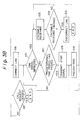
- Fig. 3 which is composed of Fig. 3A, Fig. 3B and Fig. 3C and shows the operation flow of the facsimile apparatus 2, and Fig. 4, which shows the operation flow of the pseudo-call requesting apparatus 1 of Fig. 1.
- the TEL/FAX automatically switching mode in which the aforementioned automatic TEL/FAX switching function is enabled, is set in the facsimile apparatus 2 in advance by the operator, by use of the mode selection switch (step S1).
- step S2 When there is an arrival of a call from the calling station through the telephone line L to the facsimile apparatus 2, in which the switch SW3 is normally switched to connect the telephone line L to the telephone apparatus 3 via the terminals C , CC and D (step S2), the telephone apparatus 3 starts ringing in correspondence with the call request signal, which is transmitted from the telephone exchange (not shown in Fig. 1) of the telephone line L (step S3).
- the flow branches to the step S5 and the conversation i.e. the voice communication through the telephone line L is established between the telephone apparatus 3 and the telephone apparatus of the calling station.
- step S6 If the OFF hook of the telephone apparatus 3 is not detected by the hook detection circuit 12 at the step S4 (No), this detecting operation is repeated until the predetermined ringing number of times of the telephone apparatus 3 is counted (step S6 and step S7) or until the call request from the telephone exchange is ceased (step S9). If the call request is ceased before ringing for the predetermined times at the step S9 (Yes), the telephone line L is automatically disconnected by the telephone exchange, and the operation of the facsimile system is also ended.
- the facsimile receiving unit 9 assumes the calling station is a facsimile apparatus, and is set in a condition of waiting for the arrival of the CNG (Calling Tone) signal from the calling station, and the facsimile receiving apparatus 9 keeps detecting the CNG signal (step S10) for the predetermined time period (step S11). If the CNG signal is detected within this predetermined time period at the step S10 (Yes), the flow branches to the step S12 and the prescribed facsimile receiving operation is performed by the facsimile receiving unit 9. Then, this facsimile receiving operation is continued until all of the facsimile data is transmitted (step S13). When the facsimile receiving operation is finished at the step S13 (Yes), the telephone line L is disconnected (step S14).
- the flow branches from the step S11 (Yes) to the step S15, and the DTMF signal is generated by the DTMF signal generating circuit 14 and is transmitted to the pseudo-call requesting apparatus 1 via the terminals B and BB .
- the pseudo-ringing circuit 11 generates the pseudo-ringing sound (step S16).
- step S15 The operation of the pseudo-call requesting apparatus 1 on receiving the DTMF signal from the facsimile apparatus 2 (step S15), is explained here with referring to Fig. 4.
- the inputted DTMF signal is detected by the DTMF signal detection circuit 8 (step S17). Then, corresponding to this detection of the DTMF signal, the control circuit 7 judges that the calling station is not a facsimile apparatus but a telephone apparatus. Thus, the control circuit 7 switches the switch SW1 to its open condition and switches the switch SW2 to its closed condition, so as to call the telephone apparatus 3 i.e. connect both of the pseudo-call request signal generating circuit 5 and the loop current supplying circuit 6 to the telephone apparatus 3 via the terminal D .
- the control circuit 7 directs the pseudo-call request signal generating circuit 5 to generate the pseudo-call request signal, for example 16 Hz signal, and calls the telephone apparatus 3 (step S18).
- the control circuit 7 operates the switch SW2 alternatively to its open and closed condition corresponding to the generation and cease of the pseudo-call request signal, so as to keep the line loop between the telephone apparatus 3 and the pseudo-call requesting apparatus 1 by supplying the loop current by use of the loop current supplying circuit 6, while the real call request signal from the telephone line L is ceased. In this way, the telephone apparatus 3 is kept ringing by the pseudo-call requesting apparatus 1 in the pertinent condition (step S18).
- the control circuit 7 switches the switch SW1 to its closed condition and switches the switch SW2 to its open condition, so as to connect the telephone apparatus 3 to the telephone line L via the terminals D , C , CC , BB , B and A . Consequently, the conversation i.e. the voice communication between the telephone apparatus 3 and the telephone apparatus of the calling station through the telephone tine L , can be established.
- the facsimile apparatus 2 if the OFF hook of the telephone apparatus 3 is not detected within the predetermined time period by the hook detection circuit 12 while counting the pseudo-ringing number of times, at the steps S16, S21 and S22 in Fig. 3, the facsimile apparatus 2 transmits the DTMF signal, in order to stop the call requesting operation of the pseudo-call requesting apparatus 1, by the DTMF signal generating circuit 13 (step S23), and stops the pseudo-ringing circuit 11 to ring (step S24).
- the call requesting operation by use of the pseudo-call request signal generating circuit 5 with respect to the telephone apparatus 3 is continued, until the DTMF signal from the facsimile apparatus 2 is detected by the DTMF signal detection circuit 8 (step S25). If the DTMF signal is detected at the step S25 (Yes), the flow branches to the step S27, and the pseudo-call requesting apparatus 1 stops the call request operation with respect to the telephone apparatus 3. In this way the telephone apparatus 3 stops ringing (S27), and the operation is ended.
- the circuit control unit 10 switches the switch SW3 to connect the telephone line L to the facsimile receiving unit 9 via the terminals A , B and BB .
- the facsimile receiving unit 9 assumes that the calling station is a facsimile apparatus and is set in a condition of waiting for the CNG signal from the calling station. In this manner, the facsimile receiving apparatus 9 keeps detecting the CNG signal (step S28). If the CNG signal is detected (Yes), the prescribed facsimile receiving operation is performed by the facsimile receiving unit 9 (step S12). Then, when the facsimile receiving operation is finished (step S13), the facsimile apparatus 2 disconnects the telephone line L (step S14).
- the facsimile apparatus 2 disconnects the telephone line L (step S29) and the operation is ended.
- Fig. 5 shows a timing chart of the above described operation of the pseudo-call requesting apparatus 1 from the DTMF signal detection to the OFF hook detection.
- Fig. 5 there are shown the timings of the DTMF signal inputted to the DTMF signal detection circuit 8, the open/close operation signal (SW1) outputted from the control circuit 7 to the switch SW1, the pseudo-call request signal outputted from the pseudo-call request signal generating circuit 5, the open/close operation signal (SW2) outputted from the control circuit 7 to the switch SW2, and the hook detection signal outputted from the hook detection circuit 4.
- the switch SW1 when the DTMF signal is detected by the DTMF signal detection circuit 8 at the time T1, the switch SW1 is switched to its open condition by the control circuit 7, and at the same time, the transmission of the pseudo-call request signal is started by the pseudo-call request signal generating circuit 5. Then, the switch SW2 is started to be alternatively switched to its open and close condition in synchronization with the pseudo-call request signal, and this switching operation of the switch SW2 and this transmitting operation of the pseudo-call request signal are continued until the hook detection circuit 4 detects the OFF hook condition at the time T2 and thus the conversation is enabled.
- the pseudo-call request to the telephone apparatus 3 by the pseudo-call requesting apparatus 1 is not necessary, since the operator manually responds to this call request from the telephone exchange by use of the handset 3a of the telephone apparatus 3.
- the pseudo-call requesting apparatus 1 is effective in case that the telephone apparatus 3 is connected to the facsimile apparatus 2 by the cord-less connection and is located remote from the facsimile apparatus 2, since the telephone apparatus 3 can ring by virtue of the pseudo-call requesting apparatus 1, so that the operator at the vicinity of the telephone apparatus 3, who cannot hear the pseudo-ringing sound generated by the facsimile apparatus 2, can still hear the ringing sound of the telephone apparatus 3 in this case.
- the conventional telephone apparatus 3 and the rather simple facsimile apparatus 2 having a little function i.e. a basic function necessary for the facsimile communication and a simple FAX/TEL automatically switching function (having no function to call the external telephone apparatus), can accomplish a quite convenient FAX/TEL automatically switching function, in cooperation with the pseudo-call requesting apparatus 1 which can be equipped between them in a quite versatile manner.
- the telephone apparatus 3 can ring again in the TEL/FAX automatically switching receiving operation of the facsimile system, after the conversation mode is switched over to the facsimile receiving mode, and then the facsimile apparatus 2 finds out that the calling station is the telephone apparatus. This is because the telephone apparatus 3 can receive the pseudo-call request signal at this time from the pseudo-call requesting apparatus 1 just in the same manner as receiving the real call request signal from the telephone exchange.
- the operator in the vicinity of the telephone apparatus 3 can still hear the ringing sound of the telephone apparatus 3 in this case and can establish the conversation on the telephone apparatus 3 without any problem.
- the construction of the present embodiment is also quite advantageous in that a facsimile apparatus quite similar in its specification to that of the aforementioned related art facsimile apparatus for the household use, can be employed as the facsimile apparatus 2, while the above mentioned very convenient TEL/FAX automatic switching operation can be realized with such a facsimile apparatus and a conventional type telephone apparatus, just by equipping the pseudo-call requesting apparatus 1 between them, with a benefit of making the total cost quite low.
Landscapes
- Engineering & Computer Science (AREA)
- Multimedia (AREA)
- Signal Processing (AREA)
- Facsimile Transmission Control (AREA)
- Facsimiles In General (AREA)
- Telephonic Communication Services (AREA)
Applications Claiming Priority (2)
| Application Number | Priority Date | Filing Date | Title |
|---|---|---|---|
| JP2400744A JPH04213266A (ja) | 1990-12-07 | 1990-12-07 | ファクシミリシステム |
| JP400744/90 | 1990-12-07 |
Publications (3)
| Publication Number | Publication Date |
|---|---|
| EP0490261A2 true EP0490261A2 (fr) | 1992-06-17 |
| EP0490261A3 EP0490261A3 (en) | 1992-10-28 |
| EP0490261B1 EP0490261B1 (fr) | 1996-07-17 |
Family
ID=18510624
Family Applications (1)
| Application Number | Title | Priority Date | Filing Date |
|---|---|---|---|
| EP91120853A Expired - Lifetime EP0490261B1 (fr) | 1990-12-07 | 1991-12-04 | Système de facsimilé |
Country Status (4)
| Country | Link |
|---|---|
| US (1) | US5267302A (fr) |
| EP (1) | EP0490261B1 (fr) |
| JP (1) | JPH04213266A (fr) |
| DE (1) | DE69120910T2 (fr) |
Cited By (3)
| Publication number | Priority date | Publication date | Assignee | Title |
|---|---|---|---|---|
| EP0778693A3 (fr) * | 1995-12-05 | 1999-02-10 | Sharp Kabushiki Kaisha | Appareil de communication utilisant une ligne téléphonique |
| WO1999012323A1 (fr) * | 1997-08-28 | 1999-03-11 | Koninklijke Philips Electronics N.V. | Dispositif combine comprenant un systeme de telecopie et un systeme de telephone, ainsi qu'un commutateur de telecopie actif |
| EP1185059A3 (fr) * | 2000-08-30 | 2004-04-07 | Sony Corporation | Appareil téléphonique |
Families Citing this family (11)
| Publication number | Priority date | Publication date | Assignee | Title |
|---|---|---|---|---|
| JP2895331B2 (ja) * | 1992-10-30 | 1999-05-24 | シャープ株式会社 | ファクシミリ装置 |
| JP2656196B2 (ja) * | 1992-12-16 | 1997-09-24 | 松下電送株式会社 | データ通信装置 |
| JP3249214B2 (ja) * | 1992-12-22 | 2002-01-21 | キヤノン株式会社 | ファクシミリ装置およびデータ通信装置およびその制御方法 |
| US5528385A (en) * | 1993-10-08 | 1996-06-18 | Zoom Telephonics, Inc. | Faxmodem with scanning capability |
| JP3329549B2 (ja) * | 1993-12-28 | 2002-09-30 | 松下電送システム株式会社 | 通信装置 |
| US5519768A (en) * | 1994-12-01 | 1996-05-21 | Bellsouth Corporation | Facsimile detection system and method |
| US5841843A (en) * | 1996-01-02 | 1998-11-24 | Brother International Corporation | Facsimile forwarding method and system using a simulated telephone line interface |
| KR100223213B1 (ko) * | 1996-11-28 | 1999-10-15 | 윤종용 | 복합기능을 가지는 팩시밀리에서 문서 강제 수신방법 |
| US8565386B2 (en) * | 2009-09-29 | 2013-10-22 | Avaya Inc. | Automatic configuration of soft phones that are usable in conjunction with special-purpose endpoints |
| US9516069B2 (en) | 2009-11-17 | 2016-12-06 | Avaya Inc. | Packet headers as a trigger for automatic activation of special-purpose softphone applications |
| JP6562686B2 (ja) * | 2015-04-14 | 2019-08-21 | キヤノン株式会社 | ファクシミリ装置、ファクシミリ装置の制御方法及びプログラム |
Family Cites Families (13)
| Publication number | Priority date | Publication date | Assignee | Title |
|---|---|---|---|---|
| JPS60126959A (ja) * | 1983-12-14 | 1985-07-06 | Ricoh Co Ltd | ファクシミリ中継装置 |
| JPH0342770Y2 (fr) * | 1985-02-08 | 1991-09-06 | ||
| JPS6239950A (ja) * | 1985-08-15 | 1987-02-20 | Fujitsu Ltd | 電話呼び出し方式 |
| JP2532403B2 (ja) * | 1986-09-26 | 1996-09-11 | 松下電器産業株式会社 | 回線端末装置 |
| JP2574295B2 (ja) * | 1987-05-06 | 1997-01-22 | 松下電送株式会社 | ファクシミリ装置 |
| JPS644157A (en) * | 1987-06-26 | 1989-01-09 | Hitachi Ltd | Facsimile/telephone automatic changeover system |
| CA1294078C (fr) * | 1987-09-30 | 1992-01-07 | Matahira Kotani | Appareil de communication par fac-simile |
| CA1308825C (fr) * | 1988-05-30 | 1992-10-13 | Tosho Oka | Repeteur terminal a repetition de signaux de boucle de courant continu |
| US5027385A (en) * | 1988-09-26 | 1991-06-25 | Tamura Electric Works, Ltd. | Facsimile apparatus for communicating on external and internal telephone sets |
| US4910764A (en) * | 1989-04-13 | 1990-03-20 | Product Engineering & Manufacturing, Inc. | Facsimile and voice communications interface device |
| JPH03114349A (ja) * | 1989-09-28 | 1991-05-15 | Oki Electric Ind Co Ltd | 電話機とファクシミリの自動切替方法 |
| JPH04958A (ja) * | 1990-04-18 | 1992-01-06 | Sharp Corp | ファクシミリ装置 |
| EP0458540B1 (fr) * | 1990-05-21 | 1998-01-28 | Canon Kabushiki Kaisha | Appareil de communication |
-
1990
- 1990-12-07 JP JP2400744A patent/JPH04213266A/ja active Pending
-
1991
- 1991-12-04 US US07/802,634 patent/US5267302A/en not_active Expired - Lifetime
- 1991-12-04 DE DE69120910T patent/DE69120910T2/de not_active Expired - Lifetime
- 1991-12-04 EP EP91120853A patent/EP0490261B1/fr not_active Expired - Lifetime
Cited By (4)
| Publication number | Priority date | Publication date | Assignee | Title |
|---|---|---|---|---|
| EP0778693A3 (fr) * | 1995-12-05 | 1999-02-10 | Sharp Kabushiki Kaisha | Appareil de communication utilisant une ligne téléphonique |
| US6163600A (en) * | 1995-12-05 | 2000-12-19 | Sharp Kabushiki Kaisha | Communication apparatus using telephone line |
| WO1999012323A1 (fr) * | 1997-08-28 | 1999-03-11 | Koninklijke Philips Electronics N.V. | Dispositif combine comprenant un systeme de telecopie et un systeme de telephone, ainsi qu'un commutateur de telecopie actif |
| EP1185059A3 (fr) * | 2000-08-30 | 2004-04-07 | Sony Corporation | Appareil téléphonique |
Also Published As
| Publication number | Publication date |
|---|---|
| US5267302A (en) | 1993-11-30 |
| EP0490261B1 (fr) | 1996-07-17 |
| JPH04213266A (ja) | 1992-08-04 |
| DE69120910T2 (de) | 1997-02-13 |
| DE69120910D1 (de) | 1996-08-22 |
| EP0490261A3 (en) | 1992-10-28 |
Similar Documents
| Publication | Publication Date | Title |
|---|---|---|
| US5014296A (en) | Facsimile terminal device having voice message recording capability | |
| US5146489A (en) | Dedicated line eliminator for facsimile/telephone systems | |
| US4910764A (en) | Facsimile and voice communications interface device | |
| GB2166624A (en) | Remote control unit for automatic telephone answering device | |
| US5267302A (en) | Facsimile system | |
| US5877872A (en) | Facsimile apparatus | |
| US5329580A (en) | Communication terminal adaptor | |
| EP0448312B1 (fr) | Dispositif de communication fac-similé-téléphone partagé | |
| JP3008708B2 (ja) | 電話回線に電話機とブランチ接続される通信装置 | |
| JP2529549B2 (ja) | フアクシミリ装置 | |
| JP2530466B2 (ja) | ボタン電話装置 | |
| JP3870544B2 (ja) | 通信端末装置 | |
| JP3067273B2 (ja) | ボタン電話装置 | |
| GB2130848A (en) | Telephone call transfer apparatus with receiving announcing means | |
| JPH06121027A (ja) | ファクシミリ着信規制機能付き電話機 | |
| JP3533035B2 (ja) | Fax着信の自動受信方法 | |
| JPS61237595A (ja) | 電話装置 | |
| JP3055364B2 (ja) | ファクシミリ装置 | |
| JPH09200424A (ja) | 網制御装置 | |
| JPH03179857A (ja) | ファクシミリ及び留守番電話受信方式 | |
| JPH0583457A (ja) | フアクシミリ装置 | |
| JPS61274576A (ja) | フアクシミリ装置 | |
| JPH07298025A (ja) | 音声応答装置およびファクシミリ装置 | |
| JPH0238035B2 (fr) | ||
| JPH05130359A (ja) | 自動発信機能付フアクシミリ装置の着信先への誤接続防止方法とその自動発信機能付フアクシミリ装置 |
Legal Events
| Date | Code | Title | Description |
|---|---|---|---|
| PUAI | Public reference made under article 153(3) epc to a published international application that has entered the european phase |
Free format text: ORIGINAL CODE: 0009012 |
|
| AK | Designated contracting states |
Kind code of ref document: A2 Designated state(s): DE FR GB |
|
| PUAL | Search report despatched |
Free format text: ORIGINAL CODE: 0009013 |
|
| AK | Designated contracting states |
Kind code of ref document: A3 Designated state(s): DE FR GB |
|
| 17P | Request for examination filed |
Effective date: 19930120 |
|
| 17Q | First examination report despatched |
Effective date: 19950127 |
|
| GRAH | Despatch of communication of intention to grant a patent |
Free format text: ORIGINAL CODE: EPIDOS IGRA |
|
| GRAH | Despatch of communication of intention to grant a patent |
Free format text: ORIGINAL CODE: EPIDOS IGRA |
|
| GRAA | (expected) grant |
Free format text: ORIGINAL CODE: 0009210 |
|
| AK | Designated contracting states |
Kind code of ref document: B1 Designated state(s): DE FR GB |
|
| REF | Corresponds to: |
Ref document number: 69120910 Country of ref document: DE Date of ref document: 19960822 |
|
| ET | Fr: translation filed | ||
| PLBE | No opposition filed within time limit |
Free format text: ORIGINAL CODE: 0009261 |
|
| STAA | Information on the status of an ep patent application or granted ep patent |
Free format text: STATUS: NO OPPOSITION FILED WITHIN TIME LIMIT |
|
| 26N | No opposition filed | ||
| REG | Reference to a national code |
Ref country code: GB Ref legal event code: IF02 |
|
| PGFP | Annual fee paid to national office [announced via postgrant information from national office to epo] |
Ref country code: FR Payment date: 20101224 Year of fee payment: 20 |
|
| PGFP | Annual fee paid to national office [announced via postgrant information from national office to epo] |
Ref country code: GB Payment date: 20101201 Year of fee payment: 20 |
|
| PGFP | Annual fee paid to national office [announced via postgrant information from national office to epo] |
Ref country code: DE Payment date: 20101130 Year of fee payment: 20 |
|
| REG | Reference to a national code |
Ref country code: DE Ref legal event code: R071 Ref document number: 69120910 Country of ref document: DE |
|
| REG | Reference to a national code |
Ref country code: DE Ref legal event code: R071 Ref document number: 69120910 Country of ref document: DE |
|
| REG | Reference to a national code |
Ref country code: GB Ref legal event code: PE20 Expiry date: 20111203 |
|
| PG25 | Lapsed in a contracting state [announced via postgrant information from national office to epo] |
Ref country code: GB Free format text: LAPSE BECAUSE OF EXPIRATION OF PROTECTION Effective date: 20111203 |
|
| PG25 | Lapsed in a contracting state [announced via postgrant information from national office to epo] |
Ref country code: DE Free format text: LAPSE BECAUSE OF EXPIRATION OF PROTECTION Effective date: 20111205 |