EP0490468A1 - Un dispositif à charnière bilatérale décrochable pour une boîte console de véhicule - Google Patents
Un dispositif à charnière bilatérale décrochable pour une boîte console de véhicule Download PDFInfo
- Publication number
- EP0490468A1 EP0490468A1 EP91308262A EP91308262A EP0490468A1 EP 0490468 A1 EP0490468 A1 EP 0490468A1 EP 91308262 A EP91308262 A EP 91308262A EP 91308262 A EP91308262 A EP 91308262A EP 0490468 A1 EP0490468 A1 EP 0490468A1
- Authority
- EP
- European Patent Office
- Prior art keywords
- box
- main body
- edge
- box main
- box lid
- Prior art date
- Legal status (The legal status is an assumption and is not a legal conclusion. Google has not performed a legal analysis and makes no representation as to the accuracy of the status listed.)
- Withdrawn
Links
- 230000007246 mechanism Effects 0.000 claims description 13
- 238000010276 construction Methods 0.000 abstract 1
- XEEYBQQBJWHFJM-UHFFFAOYSA-N Iron Chemical compound [Fe] XEEYBQQBJWHFJM-UHFFFAOYSA-N 0.000 description 2
- 240000007594 Oryza sativa Species 0.000 description 1
- 235000007164 Oryza sativa Nutrition 0.000 description 1
- 230000000881 depressing effect Effects 0.000 description 1
- 230000000694 effects Effects 0.000 description 1
- 229910052742 iron Inorganic materials 0.000 description 1
- 230000002093 peripheral effect Effects 0.000 description 1
- 235000009566 rice Nutrition 0.000 description 1
Images
Classifications
-
- B—PERFORMING OPERATIONS; TRANSPORTING
- B60—VEHICLES IN GENERAL
- B60R—VEHICLES, VEHICLE FITTINGS, OR VEHICLE PARTS, NOT OTHERWISE PROVIDED FOR
- B60R7/00—Stowing or holding appliances inside vehicle primarily intended for personal property smaller than suit-cases, e.g. travelling articles, or maps
- B60R7/04—Stowing or holding appliances inside vehicle primarily intended for personal property smaller than suit-cases, e.g. travelling articles, or maps in driver or passenger space, e.g. using racks
-
- E—FIXED CONSTRUCTIONS
- E05—LOCKS; KEYS; WINDOW OR DOOR FITTINGS; SAFES
- E05B—LOCKS; ACCESSORIES THEREFOR; HANDCUFFS
- E05B83/00—Vehicle locks specially adapted for particular types of wing or vehicle
- E05B83/28—Locks for glove compartments, console boxes, fuel inlet covers or the like
- E05B83/32—Locks for glove compartments, console boxes, fuel inlet covers or the like for console boxes, e.g. between passenger seats
-
- E—FIXED CONSTRUCTIONS
- E05—LOCKS; KEYS; WINDOW OR DOOR FITTINGS; SAFES
- E05D—HINGES OR SUSPENSION DEVICES FOR DOORS, WINDOWS OR WINGS
- E05D1/00—Pinless hinges; Substitutes for hinges
- E05D1/06—Pinless hinges; Substitutes for hinges consisting of two easily-separable parts
-
- E—FIXED CONSTRUCTIONS
- E05—LOCKS; KEYS; WINDOW OR DOOR FITTINGS; SAFES
- E05D—HINGES OR SUSPENSION DEVICES FOR DOORS, WINDOWS OR WINGS
- E05D15/00—Suspension arrangements for wings
- E05D15/48—Suspension arrangements for wings allowing alternative movements
- E05D15/50—Suspension arrangements for wings allowing alternative movements for opening at either of two opposite edges
- E05D15/507—Suspension arrangements for wings allowing alternative movements for opening at either of two opposite edges by detachment of the hinge from the wing or the frame
-
- E—FIXED CONSTRUCTIONS
- E05—LOCKS; KEYS; WINDOW OR DOOR FITTINGS; SAFES
- E05Y—INDEXING SCHEME ASSOCIATED WITH SUBCLASSES E05D AND E05F, RELATING TO CONSTRUCTION ELEMENTS, ELECTRIC CONTROL, POWER SUPPLY, POWER SIGNAL OR TRANSMISSION, USER INTERFACES, MOUNTING OR COUPLING, DETAILS, ACCESSORIES, AUXILIARY OPERATIONS NOT OTHERWISE PROVIDED FOR, APPLICATION THEREOF
- E05Y2201/00—Constructional elements; Accessories therefor
- E05Y2201/40—Motors; Magnets; Springs; Weights; Accessories therefor
- E05Y2201/46—Magnets
-
- E—FIXED CONSTRUCTIONS
- E05—LOCKS; KEYS; WINDOW OR DOOR FITTINGS; SAFES
- E05Y—INDEXING SCHEME ASSOCIATED WITH SUBCLASSES E05D AND E05F, RELATING TO CONSTRUCTION ELEMENTS, ELECTRIC CONTROL, POWER SUPPLY, POWER SIGNAL OR TRANSMISSION, USER INTERFACES, MOUNTING OR COUPLING, DETAILS, ACCESSORIES, AUXILIARY OPERATIONS NOT OTHERWISE PROVIDED FOR, APPLICATION THEREOF
- E05Y2900/00—Application of doors, windows, wings or fittings thereof
- E05Y2900/50—Application of doors, windows, wings or fittings thereof for vehicles
- E05Y2900/53—Type of wing
- E05Y2900/538—Interior lids
Definitions
- This invention relates to a releasable double-hinge device to be suitably used for the lid of an automobile console box or of an electric rice boiler or the door of a cabinet in order for the lid or the door to be capable of being opened from either of opposite ends and totally removed.
- an automobile is normally provided at a side of the driver's seat a with a console box b for storing small items having a lid c which is preferably hinged not only at the front end d but also at the rear end e for user's convenience.
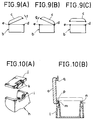
- Figs. 9(A) and 9(B) show that the lid of the console box is hinged at both the front and rear ends and therefore can be swung open in the direction of not only arrow f but also arrow g.
- Fig. 9(C) shows that the lid C can be totally removed from the console box whenever necessary.
- Fig. 10(A) and Fig. 10(B) show known releasable double-hinge devices to be used for such a console box.
- the box main body h is provided at a side as well as at the opposite side with a pair of oppositely arranged lock holes i , into which a pair of lock pins k arranged on the corresponding side of the lid i can be respectively introduced firstly by depressing them by means of a hand-operated implement (not shown) against the resilient force of a built-in spring and thereafter by releasing them into the respective holes.
- a hand-operated implement not shown
- the box main body 1 is provided at each of a pair of opposing sides with a pair of oppositely arranged pins m and n , which are received by respective C-shaped deformable bearings p or q arranged on the corresponding edges of the lid o .
- the lid o equipped with such a double-hinge device would not rotate smoothly when the engagement between the pin and the bearing is loose, whereas it should be removed and put back in position with considerable effort if a smoothly rotatable engagement is to be achieved between the pin and the bearing.
- a similar device disclosed in Japanese Patent Jitsukai Hei No. 1-86674 involves a lever to be operated for installing a lid. While a door lock device designed for a refrigerator and disclosed in Japanese Patent Tokkai Shou No. 59-52183 and a door fitting structure disclosed in Japanese Patent Tokkai Shou No. 58-86277 may fall in the same category of device in question, they have a rather complicated configuration involving latches, springs and knobs.
- a releasable double-hinge device for an automobile console box constituted by a box main body having at the top an opening and a box lid for removably covering the opening of the box main body, said device comprising two sets of an identical number of pivotal members rotatably arranged along the lateral edges of the box main body and two set of the same number of connectors arranged at respective corresponding positions under and along the lateral edges of the box lid so that the box lid may be releasably fitted to the box main body by engaging the connectors with the respective pivotal members without using a lever or a similar tool and opened and closed smoothly as the pivotal members and the respective corresponding connectors are securely and mutually engaged although it may be separated from the box main body simply by pulling it with an appropriate pulling force.
- the number of components of the device may be minimized and the operation of assembling the components may be simplified.
- a second object of the present invention is to provide a releasable double-hinge device of the type as described above further comprising shafts attached to a console main box so that pairs of pivotal members and the associated connectors are mutually and integrally connected by means of the respective shaft to ensure smooth movement of the releasable lid of the console box.
- a third object of the present invention is to provide a releasable double-hinge device of the type as described above further comprising assist-springs arranged around the respective shafts in order to urge the box lid to be opened or closed with ease.
- the first object of the invention is achieved by providing a releasable double-hinge device for an automobile console box constituted by a box main body having at the top an opening and a box lid for removably covering the opening of the box main body, said device comprising two sets of an identical number of pivotal members rotatably arranged along the lateral edges of the box main body and two set of the same number of connectors arranged at respective corresponding positions under and along the lateral edges of the box lid, each of the pairs of said pivotal members and connectors of the releasable double-hinge device arranged vis-a-vis being provided with a release-connect mechanism for releasably connecting the connector to the corresponding pivotal member when the pivotal member is held in its upright stationary position so that the box lid may be swung open around a lateral edge of the box lid when the other lateral edge is moved away from the corresponding edge of the box main body by releasing the release-connect mechanisms arranged along said
- a releasable double-hinge device for an automobile console box constituted by a box main body having at the top an opening and a box lid for removably covering the opening of the box main body as described above by referring to the first aspect of the invention, said device further comprising shafts each having a circular cross section and running through a pair of pivotal members arranged on the opposite lateral edges of the box main body to rigidly connect them, each of the connectors arranged on the box lid being provided with a U-shaped engaging groove for receiving said shaft when the connector is engaged with the corresponding pivotal member so that the connector and the pivotal member rotates around the shaft for smoothly opening or closing the box lid.
- a releasable double-hinge device for an automobile console box constituted by a box main body having at the top an opening and a box lid for removably covering the opening of the box main body as described above by referring to the first aspect of the invention, wherein each of said shafts is provided with an assist-spring having both ends rigidly fitted to the box main body and a central biasing section to abut said box lid and urge it to be opened or closed.
- each of the connectors and the corresponding pivotal member are united by means of a release-connect mechanism utilizing magnetic force or a ball stopper when the connectors arranged on a box lid are placed vis-a-vis the respective corresponding pivotal members so that the opening of a box main body is closed by the box lid.
- the box lid may be swung open around the other edge of the box main body because the connectors and the corresponding pivotal members are respectively engaged with each other. It may be clear that the box lid may alternatively be swung open in the opposite direction around the first edge of the box main body.
- box lid may be totally removed from the box main body by pulling the box lid upward to release the connectors from the corresponding pivotal members.
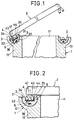
- Fig. 1 is a sectional front view of a first embodiment of the invention showing the opened box lid and only the principal area of the box main body.
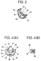
- Fig. 2 is a view similar to Fig. 1 but showing the box lid under closed condition.
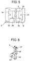
- Fig. 3 is a perspective view of one of the pivotal members of the embodiment of Fig. 1 showing only its principal area.
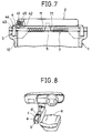
- Fig. 4(A) is a sectional front view of one of the pivotal members and a corresponding connector under connected condition
- Fig. 4(B) is an enlarged sectional front view of the pivotal member of a second embodiment of the invention.
- Fig. 5 is a schematic partial plan view of a box main body showing one of the pivotal members of the embodiment of Fig. 1 fitted therein.
- Fig. 6 is a perspective view of one of the connectors of the embodiment of Fig. 1.
- Fig. 7 is a lateral sectional view of the embodiment of Fig. 1.
- Fig. 8 is a perspective view of a known automobile console box.
- Fig. 9(A), 9(B) and 9(C) are schematic side views of the console box of Fig. 8 showing respectively when it is opened from the right, when it is opened from he left and when the box lid is totally removed.
- Fig. 10(A) is a partial perspective view of a known console box and Fig. 10(B) is a sectional side view of another known console box.
- reference numeral 1 denotes a console box main body having an opening 11 and numeral 2 denotes a box lid to cover said opening 11.
- numeral 2 denotes a box lid to cover said opening 11.
- more than one pivotal members 3, 3 are rotatably and unreleasably arranged.
- each of said pivotal members 3, 3 has a semicircular front view and comprises a peripheral wall provided with a semicircular groove 31 running along the center of its outer periphery and a thin inner section 34 to form a pair of lateral engaging ridges 32, 33 axially extending from the outer periphery of said thin inner section 34, whose open end is indented to form a connecting edge 35 which faces squarely upward when the pivotal member 3 is left stationary.
- a balancer 36 is further arranged in the pivotal member 3 to ensure its upward stationary position.
- the lateral edges 12, 13 are provided with grooves 14 to receive respective corresponding pivotal members 3, 3 as shown in Fig. 5.
- connectors 4, 4 are arranged on the inner surface of the box lid 2 at positions corresponding to those of the pivotal members 3, 3.
- each of said connectors 4, 4 has a flat fitting section 41 provided with a number of fitting bores 42 and an inverted U-shaped connector main body 44 arranged at the bottom of said fitting section 41 and having an engaging semicircular groove 43 at the top of its cut-out area.
- Said fitting section 41 can be rigidly held to the box lid 2 by means of screws 45 driven through the fitting holes 42 with the receiving groove 43 facing vis-a-vis the corresponding one of the lateral edges 12, 13 of the box main body 1 as illustrated in Fig. 7.
- a shaft 5 is arranged along the centers of rotation of the pivotal members 3, 3 on each of the lateral edges 12, 13 of the box main body 1 so that said shafts 5, 5 are received by the corresponding engaging grooves 43 when the connectors 4, 4 are arranged in position on the respective corresponding connecting edges 35, 35 of the pivotal members 3, 3.
- a release-connect mechanism 6 is further arranged to releasably connect each of the connectors 4, 4 to the corresponding one of the pivotal members 3, 3 in Figs 1 through 3.
- Such a release-connect mechanism 6 may be typically realized by preparing the connectors 4, 4 from soft iron and arranging a piece of magnet 61 on the connecting edge 35 of each of the pivotal member 3, 3 so that each of the connectors 4, 4 and the corresponding one of the pivotal members 3, 3 are attracted to each other by the magnetic force of the magnet 61 although they can be separated from each other by pulling up the connector 4 with an appropriate force.
- Fig. 4 shows an alternative release-connect mechanism, where each of the connector main bodies 44 of the connectors 4, 4 is provided with a pair of lateral engaging bores 45, 45, while a ball-shaped engaging piece 37 is releasably placed in each of said engaging bores 45, 45 with a spring 38 arranged between the engaging piece 37 and the engaging bore 45 so that the former may partly come out of and go back into the bore 45 under the effect of the spring 38.
- Reference numeral 39 in Fig. 4 denotes a flange of the engaging bore 45 arranged to prevent the engaging piece 37 from totally coming out of the bore 45.
- each of the shafts 5 is provided with an assist-spring 7 having a central biasing section 71, whose both ends are rigidly fitted to the edges 12, 13 of the box main body 1 while the central biasing section 71 abuts the box lid 2 to urge the latter to open or close it so that the box lid 2 may be fully or partly automatically opened and closed under the effort of the assist spring 7.
- the lid of the console box can be opened or closed from either lateral side to store small items in the box or take out them from it and totally removed from the console box main body if it is not needed.
- no lever or a similar tool is required so that the operation of putting the lid in position and that of separating it from the box can be performed very quickly.
- such a device comprises a minimum number of components, they can be assembled with utmost ease and manufactured at a reduced cost.
- the connection between the connectors and the respective pivotal members is secured and smooth movement of the lid is ensured because of the use of additional shafts.
- the user can enjoy smooth movement of the lid to a maximum degree because of the use of assist-springs for the shafts.
Landscapes
- Engineering & Computer Science (AREA)
- Mechanical Engineering (AREA)
- Vehicle Step Arrangements And Article Storage (AREA)
- Closures For Containers (AREA)
Applications Claiming Priority (2)
| Application Number | Priority Date | Filing Date | Title |
|---|---|---|---|
| JP410790/90 | 1990-12-14 | ||
| JP41079090A JP3208453B2 (ja) | 1990-12-14 | 1990-12-14 | 自動車のコンソールボックス用等の両開き開閉装置 |
Publications (1)
| Publication Number | Publication Date |
|---|---|
| EP0490468A1 true EP0490468A1 (fr) | 1992-06-17 |
Family
ID=18519897
Family Applications (1)
| Application Number | Title | Priority Date | Filing Date |
|---|---|---|---|
| EP91308262A Withdrawn EP0490468A1 (fr) | 1990-12-14 | 1991-09-10 | Un dispositif à charnière bilatérale décrochable pour une boîte console de véhicule |
Country Status (3)
| Country | Link |
|---|---|
| US (1) | US5210906A (fr) |
| EP (1) | EP0490468A1 (fr) |
| JP (1) | JP3208453B2 (fr) |
Cited By (18)
| Publication number | Priority date | Publication date | Assignee | Title |
|---|---|---|---|---|
| EP0599031A1 (fr) * | 1992-11-23 | 1994-06-01 | Kiepe Elektrik GmbH | Conteneur du toit pour le logement de composants électriques et électromécaniques de commande d'entraînement et de véhicules ferroviaires et des trolleybus |
| FR2715690A1 (fr) * | 1994-01-28 | 1995-08-04 | Moreno Fabrice | Agencement de support pivotant d'un ouvrant à une partie fixe formant dormant. |
| US5647652A (en) * | 1995-12-20 | 1997-07-15 | Chrysler Corporation | Dual-hinged center console |
| DE10151704C2 (de) * | 2001-10-19 | 2003-10-23 | Draexlmaier Lisa Gmbh | Deckelöffnungsmechanismus und Fahrzeugmittelkonsole |
| WO2004000607A1 (fr) * | 2002-06-25 | 2003-12-31 | Daimlerchrysler Ag | Compartiment de rangement pour un vehicule |
| DE10247453B4 (de) * | 2002-10-11 | 2005-03-24 | Lisa Dräxlmaier GmbH | Zweiseitig zu öffnender Behälter |
| CN101400870B (zh) * | 2006-03-14 | 2012-09-26 | 株式会社利富高 | 双开盖装置及中心操纵箱 |
| GB2503953A (en) * | 2012-07-14 | 2014-01-15 | Jonathan Stephen Prestwich | A door with magnetic hinges which can be opened from two opposite edges |
| CN103552513A (zh) * | 2013-10-12 | 2014-02-05 | 芜湖市顺昌汽车配件有限公司 | 一种车用扶手箱结构 |
| DE102013014155A1 (de) | 2013-08-24 | 2014-04-24 | Daimler Ag | Behälter umfassend ein Ablagefach mit einer Wandung und einen Auflagedeckel zum Verschließen des Gehäusefachs |
| WO2014124730A1 (fr) * | 2013-02-12 | 2014-08-21 | Daimler Ag | Console centrale destinée à un véhicule automobile |
| CN105275292A (zh) * | 2015-10-15 | 2016-01-27 | 苏州拓科装饰工程有限公司 | 一种铰链 |
| CN107468016A (zh) * | 2017-09-29 | 2017-12-15 | 南丹县职业教育中心 | 一种便携式保温杯 |
| CN108652212A (zh) * | 2017-03-31 | 2018-10-16 | 霍沃思公司 | 双铰链磁性盖装置 |
| CN109421609A (zh) * | 2017-08-28 | 2019-03-05 | 丰田合成株式会社 | 两开收纳装置 |
| US10717390B2 (en) | 2016-05-18 | 2020-07-21 | Shanghai Yanfeng Jinqiao Automotive Trim Systems Co. Ltd. | Console assembly for vehicle interior |
| US11572723B2 (en) | 2019-02-27 | 2023-02-07 | Shanghai Yanfeng Jinqiao Automotive Triim Systems Co. Ltd. | Vehicle interior component |
| US12036951B2 (en) | 2020-09-28 | 2024-07-16 | Ford Global Technologies, Llc | Storage box for a vehicle |
Families Citing this family (61)
| Publication number | Priority date | Publication date | Assignee | Title |
|---|---|---|---|---|
| JPH0631554U (ja) * | 1992-09-30 | 1994-04-26 | 池田物産株式会社 | 両開き蓋装置 |
| DE4328821C2 (de) * | 1993-08-27 | 1998-06-04 | Eckhard Baermann | Beidseitig einsetzbare Scharnieranordnung |
| US6116674A (en) * | 1997-09-05 | 2000-09-12 | Ford Motor Company | Removable console for use with a vehicle |
| US6003716A (en) * | 1997-09-05 | 1999-12-21 | Ford Motor Company | Dual opening console |
| AT406783B (de) * | 1998-02-23 | 2000-09-25 | Kappel Hannes | Beschlag |
| US6399882B1 (en) | 1998-10-02 | 2002-06-04 | Siemens Energy & Automation, Inc. | Dual-hinged door for an electrical power distribution busway |
| US6250729B1 (en) | 1999-09-27 | 2001-06-26 | Ford Global Technologies, Inc. | Dual opening sliding console for use with a vehicle |
| FR2816563B1 (fr) * | 2000-11-14 | 2003-02-28 | Sai Automotive Allibert Ind | Console centrale de vehicule automobile |
| US7089627B2 (en) * | 2001-04-23 | 2006-08-15 | L'oreal Usa, Inc. | Magnetic hinge and device including magnetically-attracted plates |
| KR100642028B1 (ko) * | 2001-08-21 | 2006-11-06 | 로레알 유에스에이 인코포레이티드 | 화장품 케이스 |
| US6761388B2 (en) | 2002-01-08 | 2004-07-13 | Plastech Engineered Products | Console system having a double-hinged lid |
| US20030167599A1 (en) * | 2002-03-07 | 2003-09-11 | David Seidler | Magnetic hinge |
| US7055216B2 (en) * | 2002-03-07 | 2006-06-06 | Concept Workshop Worldwide Llc | Magnetic hinge |
| KR20030082803A (ko) * | 2002-04-18 | 2003-10-23 | 기아자동차주식회사 | 차량의 센터콘솔 잠금장치 |
| KR20030086806A (ko) * | 2002-05-07 | 2003-11-12 | 현대자동차주식회사 | 자동차용 2웨이 오픈형 콘솔박스 커버구조 |
| US6908096B2 (en) * | 2002-09-06 | 2005-06-21 | Uara Services, Inc. | Cover, including hinged door, for trailer hitch receivers of multiple sizes and methods |
| US6840785B2 (en) * | 2003-03-07 | 2005-01-11 | Thomas & Betts International, Inc. | Cover assembly for an electrical box |
| US7121412B2 (en) * | 2003-07-09 | 2006-10-17 | Hubbell Incorporated | Hinged swing bracket assembly for a rack system |
| TWI231137B (en) * | 2004-02-09 | 2005-04-11 | Primax Electronics Ltd | Machinery system having an upper body capable of being positioned at any angle |
| DE102004025655B3 (de) * | 2004-05-26 | 2005-10-27 | Lisa Dräxlmaier GmbH | Klapp-Deckel eines Gehäuses |
| US20060010650A1 (en) * | 2004-07-16 | 2006-01-19 | French Lon G | Double hinge apparatus |
| US7665186B2 (en) * | 2006-10-30 | 2010-02-23 | Sony Ericsson Mobile Communications Ab | Hinge with anti-skew features |
| US7810862B2 (en) * | 2007-02-14 | 2010-10-12 | 89908, Inc. | Dual access vehicle storage assembly |
| US7748762B2 (en) * | 2007-09-19 | 2010-07-06 | Honda Motor Co., Ltd. | Vehicle console assembly |
| US20090100732A1 (en) * | 2007-10-19 | 2009-04-23 | Concept Workshop Worldwide, Llc | Magnetic display device |
| ES2642051T3 (es) | 2008-05-28 | 2017-11-15 | Steelcase Inc. | Conjunto de superficie de trabajo |
| DE602008004497D1 (de) * | 2008-07-16 | 2011-02-24 | Siemens Milltronics Proc Instr | Klappverpackungsbehälter |
| US20110085297A1 (en) * | 2009-10-14 | 2011-04-14 | General Dynamics C4 Systems, Inc. | Self Releasing Hinge |
| CA3002291C (fr) * | 2010-03-09 | 2019-11-26 | Philip Sandler | Epandeur de materiaux monte sur camion |
| US8925469B2 (en) | 2010-05-28 | 2015-01-06 | Steelcase Inc. | Grommet assembly for work surfaces |
| JP5444200B2 (ja) * | 2010-12-06 | 2014-03-19 | 株式会社八木研 | 扉開閉構造 |
| JP4846046B1 (ja) * | 2010-08-06 | 2011-12-28 | 株式会社八木研 | 扉開閉構造 |
| CN103052760B (zh) * | 2010-08-06 | 2015-08-05 | 株式会社八木研 | 门开闭构造 |
| US8517792B1 (en) * | 2011-03-09 | 2013-08-27 | Primos, Inc. | Box call with magnetic hinge and methods |
| US8360269B1 (en) * | 2011-07-09 | 2013-01-29 | General Jack Technology Ltd. | Communication box |
| US8424948B2 (en) * | 2011-08-30 | 2013-04-23 | GM Global Technology Operations LLC | Vehicle with decklid hold-open assist |
| US9676340B2 (en) * | 2012-06-20 | 2017-06-13 | Faurecia Interior Systems India Pvt. Ltd. | Storage device arranged to be opened in two different directions |
| JP6044759B2 (ja) * | 2012-07-12 | 2016-12-14 | カシオ計算機株式会社 | 鍵盤楽器 |
| US9272831B2 (en) * | 2012-08-15 | 2016-03-01 | Nice-Pak Products, Inc. | Dispenser |
| US20140090634A1 (en) * | 2012-09-28 | 2014-04-03 | Fan Li | Reduce impact by barbecue smoke |
| US9302628B2 (en) * | 2013-04-02 | 2016-04-05 | Lund Motion Products, Inc. | Dual access vehicle storage assembly |
| DE102013019389A1 (de) * | 2013-11-18 | 2015-05-21 | GM Global Technology Operations LLC (n. d. Ges. d. Staates Delaware) | Verschließbare Vorrichtung zur Aufbewahrung von Gegenständen in einem Fahrzeug |
| FR3016386A1 (fr) * | 2014-01-14 | 2015-07-17 | Marc Tauss | Ensemble support/porte multidirectionnelle |
| DE202014000605U1 (de) * | 2014-01-22 | 2015-04-23 | Grass Gmbh & Co. Kg | Vorrichtung zur Verbindung eines bewegbaren Möbelteils wie Klappe, Tür oder dergleichen, mit einem feststehenden Möbelteil |
| MX390023B (es) * | 2014-04-24 | 2025-03-20 | Upsite Tech Inc | Sistema de puerta para control de flujo de aire. |
| DE202014009636U1 (de) | 2014-12-03 | 2016-03-04 | GM Global Technology Operations LLC (n. d. Ges. d. Staates Delaware) | Staufach für ein Fahrzeug und Fahrzeug mit dem Staufach |
| WO2016140788A1 (fr) * | 2015-03-04 | 2016-09-09 | Bobrick Washroom Equipment, Inc. | Système de séparation et de fermeture pour élément de séparation |
| US10724264B2 (en) | 2015-11-18 | 2020-07-28 | Sundance Spas, Inc. | Intermittent locking door mechanism |
| US10344513B2 (en) | 2017-08-18 | 2019-07-09 | Shanghai Yangeng Jinqiao Automotive Trim Systems Co. Ltd. | Component for vehicle interior |
| CN108179941A (zh) * | 2017-12-31 | 2018-06-19 | 重庆市合川区刘彬家具厂 | 家具柜门磁性铰链结构 |
| CN108193970A (zh) * | 2017-12-31 | 2018-06-22 | 重庆市合川区刘彬家具厂 | 一种家具柜门磁性铰链结构 |
| USD1080371S1 (en) | 2022-12-27 | 2025-06-24 | New Revo Brand Group, Llc | Clip for vise accessories |
| US12560400B2 (en) | 2018-08-29 | 2026-02-24 | New Revo Brand Group, Llc | Accessory for working device |
| US12384005B2 (en) | 2018-08-29 | 2025-08-12 | New Revo Brand Group, Llc | Ball joint system and support device |
| US11706894B2 (en) * | 2019-08-05 | 2023-07-18 | Panduit Corp. | Cable manager with a hinged door |
| US11582538B2 (en) * | 2019-08-05 | 2023-02-14 | Panduit Corp. | Horizontal cable manager with a hinged door |
| EP4314925A4 (fr) | 2021-03-26 | 2025-07-02 | Commscope Technologies Llc | Système de panneau de communications |
| SE547201C2 (en) * | 2021-07-08 | 2025-05-27 | Rolf Palmgren | Electromagnetic gate arrangement, a maze comprising an electromagnetic gate arrangement and a method for operating an electromagnetic gate arrangement |
| KR102675243B1 (ko) * | 2022-03-23 | 2024-06-14 | 카이엠 주식회사 | 자동차용 콘솔 개폐장치 |
| CN114987344B (zh) * | 2022-06-07 | 2025-07-11 | 上海延锋金桥汽车饰件系统有限公司 | 一种车辆内部部件 |
| KR102759142B1 (ko) * | 2022-06-13 | 2025-01-24 | 카이엠 주식회사 | 마찰힌지를 구비하는 양방향 개폐형 자동차 암레스트 |
Citations (3)
| Publication number | Priority date | Publication date | Assignee | Title |
|---|---|---|---|---|
| DE1067577B (de) * | 1958-03-28 | 1959-10-22 | Junker & Ruh Ag | Schliessvorrichtung fuer Back- oder Bratofen-Klapptueren |
| DE3111595A1 (de) * | 1981-03-24 | 1982-10-28 | Mukai, Taichi | Im eingebauten zustand wahlweise beliebig oft links oder rechts anschlagbare tuer |
| FR2623779A1 (fr) * | 1987-11-30 | 1989-06-02 | Nifco Inc | Dispositif d'ouverture/fermeture |
Family Cites Families (18)
| Publication number | Priority date | Publication date | Assignee | Title |
|---|---|---|---|---|
| US2791346A (en) * | 1953-07-08 | 1957-05-07 | Gen Motors Corp | Magnetic receiver |
| US2790992A (en) * | 1954-08-11 | 1957-05-07 | Walter E Schirmer | Hinge construction |
| US2817870A (en) * | 1954-12-22 | 1957-12-31 | Int Harvester Co | Combined hinge and latch device |
| US3152716A (en) * | 1961-08-02 | 1964-10-13 | Expandolite Inc | Container |
| US3388418A (en) * | 1965-07-27 | 1968-06-18 | Monarch Tool & Machinery Compa | Magnetic hinge |
| US3436860A (en) * | 1966-03-21 | 1969-04-08 | Fred W James | Door hinge and latch mechanism |
| GB1218457A (en) * | 1967-10-25 | 1971-01-06 | Hettich F Kg | Hinges |
| DE6923018U (de) * | 1969-06-10 | 1970-01-22 | Kunststoff Gmbh | Moebel mit scharnier und zuhaltevorrichtung |
| DE2016398A1 (de) * | 1970-04-07 | 1971-11-04 | Lautenschlaeger Kg Karl | Schnäpperscharnier für Möbeltüre |
| US3728819A (en) * | 1970-04-28 | 1973-04-24 | Kiekert Soehne Arn | Vehicle doors |
| DE2325057C3 (de) * | 1973-05-17 | 1984-01-05 | Fa. Richard Heinze, 4900 Herford | Möbelscharnier |
| AT353135B (de) * | 1973-12-12 | 1979-10-25 | Praemeta | Verdeckt anbringbares, seiten-und tiefenein- stellbares scharnier fuer tuerfluegel mit einem oeffnungswinkel bis zu 180 grad, insbesondere moebelscharnier |
| US4126964A (en) * | 1977-09-08 | 1978-11-28 | Anderson Ernest L | Pivotal sliding sash window |
| JPS5886277A (ja) * | 1981-11-18 | 1983-05-23 | 日本電気ホームエレクトロニクス株式会社 | 扉取付構体 |
| JPS5952183A (ja) * | 1982-09-17 | 1984-03-26 | 株式会社日立製作所 | 冷蔵庫の扉閉止装置 |
| JPS6090042A (ja) * | 1983-10-24 | 1985-05-21 | Mitsui Toatsu Chem Inc | 銀触媒の製造法 |
| JPS60242275A (ja) * | 1984-05-14 | 1985-12-02 | 日産自動車株式会社 | 自動車のコンソ−ルボツクス |
| JPS6486674A (en) * | 1987-09-28 | 1989-03-31 | Pfu Ltd | Image input device |
-
1990
- 1990-12-14 JP JP41079090A patent/JP3208453B2/ja not_active Expired - Fee Related
-
1991
- 1991-08-28 US US07/750,584 patent/US5210906A/en not_active Expired - Fee Related
- 1991-09-10 EP EP91308262A patent/EP0490468A1/fr not_active Withdrawn
Patent Citations (4)
| Publication number | Priority date | Publication date | Assignee | Title |
|---|---|---|---|---|
| DE1067577B (de) * | 1958-03-28 | 1959-10-22 | Junker & Ruh Ag | Schliessvorrichtung fuer Back- oder Bratofen-Klapptueren |
| DE3111595A1 (de) * | 1981-03-24 | 1982-10-28 | Mukai, Taichi | Im eingebauten zustand wahlweise beliebig oft links oder rechts anschlagbare tuer |
| FR2623779A1 (fr) * | 1987-11-30 | 1989-06-02 | Nifco Inc | Dispositif d'ouverture/fermeture |
| JPH0186674U (fr) * | 1987-11-30 | 1989-06-08 |
Cited By (24)
| Publication number | Priority date | Publication date | Assignee | Title |
|---|---|---|---|---|
| EP0599031A1 (fr) * | 1992-11-23 | 1994-06-01 | Kiepe Elektrik GmbH | Conteneur du toit pour le logement de composants électriques et électromécaniques de commande d'entraînement et de véhicules ferroviaires et des trolleybus |
| FR2715690A1 (fr) * | 1994-01-28 | 1995-08-04 | Moreno Fabrice | Agencement de support pivotant d'un ouvrant à une partie fixe formant dormant. |
| US5647652A (en) * | 1995-12-20 | 1997-07-15 | Chrysler Corporation | Dual-hinged center console |
| DE10151704C2 (de) * | 2001-10-19 | 2003-10-23 | Draexlmaier Lisa Gmbh | Deckelöffnungsmechanismus und Fahrzeugmittelkonsole |
| WO2004000607A1 (fr) * | 2002-06-25 | 2003-12-31 | Daimlerchrysler Ag | Compartiment de rangement pour un vehicule |
| US7523975B2 (en) | 2002-06-25 | 2009-04-28 | Daimler Ag | Storage compartment for a vehicle |
| DE10247453B4 (de) * | 2002-10-11 | 2005-03-24 | Lisa Dräxlmaier GmbH | Zweiseitig zu öffnender Behälter |
| CN101400870B (zh) * | 2006-03-14 | 2012-09-26 | 株式会社利富高 | 双开盖装置及中心操纵箱 |
| GB2503953A (en) * | 2012-07-14 | 2014-01-15 | Jonathan Stephen Prestwich | A door with magnetic hinges which can be opened from two opposite edges |
| WO2014124730A1 (fr) * | 2013-02-12 | 2014-08-21 | Daimler Ag | Console centrale destinée à un véhicule automobile |
| WO2015028117A1 (fr) * | 2013-08-24 | 2015-03-05 | Daimler Ag | Récipient comprenant un compartiment de rangement muni d'une paroi et un couvercle à poser pour fermer le compartiment de rangement |
| DE102013014155A1 (de) | 2013-08-24 | 2014-04-24 | Daimler Ag | Behälter umfassend ein Ablagefach mit einer Wandung und einen Auflagedeckel zum Verschließen des Gehäusefachs |
| CN103552513A (zh) * | 2013-10-12 | 2014-02-05 | 芜湖市顺昌汽车配件有限公司 | 一种车用扶手箱结构 |
| CN103552513B (zh) * | 2013-10-12 | 2016-03-23 | 芜湖市顺昌汽车配件有限公司 | 一种车用扶手箱结构 |
| CN105275292A (zh) * | 2015-10-15 | 2016-01-27 | 苏州拓科装饰工程有限公司 | 一种铰链 |
| US10737628B2 (en) | 2016-05-18 | 2020-08-11 | Shanghai Yanfeng Jinqiao Automotive Trim Systems Co. Ltd. | Console assembly for vehicle interior |
| US10717390B2 (en) | 2016-05-18 | 2020-07-21 | Shanghai Yanfeng Jinqiao Automotive Trim Systems Co. Ltd. | Console assembly for vehicle interior |
| CN108652212A (zh) * | 2017-03-31 | 2018-10-16 | 霍沃思公司 | 双铰链磁性盖装置 |
| CN109421609A (zh) * | 2017-08-28 | 2019-03-05 | 丰田合成株式会社 | 两开收纳装置 |
| CN109421609B (zh) * | 2017-08-28 | 2021-09-17 | 丰田合成株式会社 | 两开收纳装置 |
| CN107468016B (zh) * | 2017-09-29 | 2019-04-02 | 南丹县职业教育中心 | 一种便携式保温杯 |
| CN107468016A (zh) * | 2017-09-29 | 2017-12-15 | 南丹县职业教育中心 | 一种便携式保温杯 |
| US11572723B2 (en) | 2019-02-27 | 2023-02-07 | Shanghai Yanfeng Jinqiao Automotive Triim Systems Co. Ltd. | Vehicle interior component |
| US12036951B2 (en) | 2020-09-28 | 2024-07-16 | Ford Global Technologies, Llc | Storage box for a vehicle |
Also Published As
| Publication number | Publication date |
|---|---|
| JP3208453B2 (ja) | 2001-09-10 |
| US5210906A (en) | 1993-05-18 |
| JPH04215543A (ja) | 1992-08-06 |
Similar Documents
| Publication | Publication Date | Title |
|---|---|---|
| US5210906A (en) | Releasable double-hinge device for an automobile console box | |
| US5173992A (en) | Releasable double-hinge device for an automobile console box | |
| US8100453B2 (en) | Lid device opened at both sides and center console box | |
| US5144720A (en) | Releasable double-hinge device for an automobile console box | |
| US20020163209A1 (en) | Inner handle assembly of a sliding door | |
| US5187836A (en) | Door hinge arrangement for opening the door at either side | |
| JPH07301484A (ja) | ドア開閉装置 | |
| EP0551560A1 (fr) | Serrure pour portes coulissantes avec deux pênes-crochets montés en directions opposées | |
| US5782510A (en) | Glove box latch | |
| CN212615875U (zh) | 合屏闭锁枢纽器 | |
| KR101652772B1 (ko) | 차량용 암레스트 힌지구조 | |
| CN208827664U (zh) | 可多向开启的盖体与汽车扶手箱 | |
| JP7042394B2 (ja) | 洗濯機 | |
| TWI646246B (zh) | 門體開闔裝置及具備此門體開闔裝置的櫃體 | |
| TWM632391U (zh) | 鉸鏈 | |
| JPH10196190A (ja) | 家具の開閉部材の係止機構 | |
| KR100195521B1 (ko) | 자동차의 리어콘솔 개폐장치 | |
| JPH0216354Y2 (fr) | ||
| KR100451068B1 (ko) | 글로브박스의 체결구조 | |
| JPH0216353Y2 (fr) | ||
| JPS6017508Y2 (ja) | 折畳み扉の蝶番開閉装置 | |
| JPH02106943U (fr) | ||
| JPH0848189A (ja) | コンソールボックスにおけるリッドの開閉装置 | |
| US20060059658A1 (en) | Hinge member and a combination of a containing structure, lid and hinge combination and method | |
| KR910003558Y1 (ko) | 냉장고의 좌,우 개문 장치 |
Legal Events
| Date | Code | Title | Description |
|---|---|---|---|
| PUAI | Public reference made under article 153(3) epc to a published international application that has entered the european phase |
Free format text: ORIGINAL CODE: 0009012 |
|
| AK | Designated contracting states |
Kind code of ref document: A1 Designated state(s): DE FR GB |
|
| 17P | Request for examination filed |
Effective date: 19921029 |
|
| 17Q | First examination report despatched |
Effective date: 19940729 |
|
| STAA | Information on the status of an ep patent application or granted ep patent |
Free format text: STATUS: THE APPLICATION IS DEEMED TO BE WITHDRAWN |
|
| 18D | Application deemed to be withdrawn |
Effective date: 19941210 |