EP0490716B1 - Procédé et dispositif pour corriger l'effet de pendage dans un mesure d'induction d'un puits et la production d'un enregistrement correspondant à cette correction - Google Patents
Procédé et dispositif pour corriger l'effet de pendage dans un mesure d'induction d'un puits et la production d'un enregistrement correspondant à cette correction Download PDFInfo
- Publication number
- EP0490716B1 EP0490716B1 EP91403035A EP91403035A EP0490716B1 EP 0490716 B1 EP0490716 B1 EP 0490716B1 EP 91403035 A EP91403035 A EP 91403035A EP 91403035 A EP91403035 A EP 91403035A EP 0490716 B1 EP0490716 B1 EP 0490716B1
- Authority
- EP
- European Patent Office
- Prior art keywords
- tbt
- formation
- dip
- induction
- dip angle
- Prior art date
- Legal status (The legal status is an assumption and is not a legal conclusion. Google has not performed a legal analysis and makes no representation as to the accuracy of the status listed.)
- Expired - Lifetime
Links
Images










Classifications
-
- G—PHYSICS
- G01—MEASURING; TESTING
- G01V—GEOPHYSICS; GRAVITATIONAL MEASUREMENTS; DETECTING MASSES OR OBJECTS; TAGS
- G01V3/00—Electric or magnetic prospecting or detecting; Measuring magnetic field characteristics of the earth, e.g. declination, deviation
- G01V3/18—Electric or magnetic prospecting or detecting; Measuring magnetic field characteristics of the earth, e.g. declination, deviation specially adapted for well-logging
- G01V3/26—Electric or magnetic prospecting or detecting; Measuring magnetic field characteristics of the earth, e.g. declination, deviation specially adapted for well-logging operating with magnetic or electric fields produced or modified either by the surrounding earth formation or by the detecting device
- G01V3/28—Electric or magnetic prospecting or detecting; Measuring magnetic field characteristics of the earth, e.g. declination, deviation specially adapted for well-logging operating with magnetic or electric fields produced or modified either by the surrounding earth formation or by the detecting device using induction coils
-
- G—PHYSICS
- G01—MEASURING; TESTING
- G01V—GEOPHYSICS; GRAVITATIONAL MEASUREMENTS; DETECTING MASSES OR OBJECTS; TAGS
- G01V3/00—Electric or magnetic prospecting or detecting; Measuring magnetic field characteristics of the earth, e.g. declination, deviation
- G01V3/38—Processing data, e.g. for analysis, for interpretation, for correction
Definitions
- the subject matter of the present invention relates to a well logging computer software which corrects an induction log for dip and well deviation effects.
- Induction logging measures the resistivity (or its inverse, conductivity) of the formation by first inducing eddy currents to flow in the formations in response to an AC transmitter signal, and then measuring a phase component signal in a receiver signal generated by the presence of the eddy currents.
- Variations in the magnitude of the eddy currents in response to variations in formation conductivity are reflected as variations in the receiver signal.
- the magnitude of a phase component of the receiver signal, that component in-phase with the transmitter signal is indicative of the conductivity of the formation.
- a signal generator operates to produce an AC transmitter signal which is applied to a transmitter coil.
- the current in the transmitter coil induces in the formations a magnetic field, which, in turn, causes eddy currents to flow in the formations.
- the magnetic field of the transmitter is coupled into a receiver coil R thereby generating a receiver signal
- Logging tools having "a receiver coil” and "a transmitter coil” each of which may be comprised of one or more coils arranged in a predetermined geometrical fashion to obtain a desired response are commonly used.
- the receiver signal is then generally amplified and applied to one or more phase sensitive detectors (PSDs).
- PSDs phase sensitive detectors
- Each PSD detects a phase component signal having the same phase as a phase reference signal which is also applied to the detector.
- the phase reference signal has a predetermined phase relationship to the current in the transmitter coil(s).
- the output of the PSD(s) may be further processed downhole, or may be sent uphole to surface equipment for processing or display to an operating engineer. Such processing may be accomplished using many well known techniques, including phasor deconvolution processing taught by U.S. Patent 4,513,376 issued to T. Barber on April 23, 1985; and U.S. Patent 4,471,436 issued to R. Schaefer and T. Barber on September 11, 1984.
- Induction logs produced by the above referenced art are interpreted through algorithms and models that assume azimuthal symmetry about the borehole. In reality, either formation dip or well deviation often destroys this symmetry.
- Figure 1 shows the assumed symmetry for most induction modeling.
- the bedding planes are perpendicular to the axis of the induction sonde, and the induced current in the formation does not cross any of the bed boundaries.
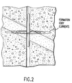
- Figure 2 shows the dip case.
- the formation currents are forced to cross the bed boundaries.
- the response of the induction tool to the formation layers in the presence of dip has been studied in the literature.
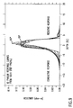
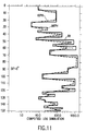
- Figure 3 shows the effect of dip on the deep induction array (ID) with traditional processing (ILD log) in a 50:1 contrast resistive bed.
- ID deep induction array
- ILD log traditional processing
- the logs do not show much change in the maximum resistivity level in the resistive bed with increasing dip because the large error is dominated by shoulder effect (shoulder effect refers to the tendency of induction arrays to include beds above and below the zone of interest into the measurement. This leads to measurements that are in error in resistive beds).
- shoulder effect refers to the tendency of induction arrays to include beds above and below the zone of interest into the measurement. This leads to measurements that are in error in resistive beds).
- the effect of apparent dip on logs with other environmental effects corrected is different from the traditional logs.
- FIG. 4 shows the deep induction array (ID) processed using the Phasor method (deep induction array Phasor, or IDPH).3
- IDPH deep induction array Phasor
- the computer receiving a plurality of formation parameter data "sigma(j-n)" and, using the correction algorithm, produces a correct curve shape of formation parameters "sigma F " for an induction log when a tool is disposed at an apparent dip angle in resistive beds having a plurality of bedding planes
- the correction algorithm being mathematically presented in equation 13
- the correction algorithm developing a filter h(a) for each dip angle "a”, such that, when the filter "h(a)" is multiplied by or convolved with a particular formation parameter "sigma(j-n)", a corrected formation parameter "sigma F " is produced, the corrected formation parameter being an estimate of a formation parameter, such as conductivity, that is made in the absence of apparent dip.
- phasor logs are corrected for all other environmental effects at zero dip by assuming that the various effects (shoulder effect, borehole effect, and invasion effects) are separable, and can be corrected in sequence.
- dip is most probably not fully separable from other environmental effects, there are a number of significant examples where it should be nearly so, such as in wells drilled with oil-based mud.
- An algorithm based on the assumption of separability is outlined in the following sections.
- a correction algorithm has been developed which improves the accuracy of the readings in the resistive bed, but which does not attempt to reduce the apparent thickening of said resistive beds.
- the charge-buildup effects which lead to this apparent thickening are quite nonlinear, depending strongly on the conductivity contrast across the boundary.
- the increase in shoulder effect with dip angle is approximately linear in both contrast and conductivity magnitude.
- This near-linearity allows a correction algorithm to be developed using the inverse-filter method.
- the algorithm as currently developed gives greatly improved resistivity accuracy in resistive beds at apparent dip angles up to 70 degrees. Tests on a large number of computed logs confirm the apparent linearity of the main part of the dip effect.
- the invention contemplates a method for correcting induction logs for the errors introduced when the induction sonde is not perpendicular to the formation bedding planes.
- This dip correction method uses an inverse filter derived from response functions that describe mathematically the response of the induction tool as it crosses the bedding planes at an angle other than perpendicular. At a given fixed angle, this response function is unique.
- the inverse filter is computed to correct the distortions in the response introduced by the apparent dip angle and to return to a response that would have been obtained if the induction sonde, had been disposed perpendicular to the bedding planes.
- the filters are derived from response functions computed after the logs have been corrected to the true bed thickness (TBT) reference frame to remove the geometrical effects of a longer path through the formation when the borehole is not perpendicular to the bedding planes.
- TBT true bed thickness
- Such filters are computed for angles every 10 degrees and the correct result is obtained from interpolation between between the defined filter angles. Preferred details and structures are hereinafter more particularly described.
- the explicit algorithm for doing dip correction with filters derived from step-profiles involves several steps. These are:
- the invention of this specification is a Dip Correction Algorithm adapted to be used in association with a well logging truck computer which produces an induction log, for correcting an error introduced in the induction log by dip effect by means of inverse filters which are computed using log response functions derived from simple dipping formation models.
- the response function has the character of a set of weights by which one can determine what fraction of the total signal at a single measure station in the log came from a particular element of formation. This has the mathematical form of a convolution such that the measured conductivity ⁇ m can be related to the formation conductivity distribution ⁇ F through the response function g v by the convolution operation
- the new technique introduced here involves using forward models of the induction process to compute the response in a simple step-profile formation at a given dip angle.
- Equation (B) The response function derived by the use of equation (B) satisfies Equation (A), so that it can then be used to derive an inverse filter for the distortions produced by the dip using standard methods.
- the essence of the subject invention is the development of a method to find a response function in non-azimuthally symmetrical formation geometries, and the application of that method to develop a correction for the errors introduced into the induction log by dip effect.
- a transmitter coil T and a receiver coil R are mounted on a support member S having a transmitter-receiver spacing L for investigating a formation F.
- the transmitter current induces eddy currents in the formation, one loop of which is shown diagrammatically as a circle at a point P having cylindrical coordinates P(rho,z) with a distance between the point P and transmitter or receiver being shown as r T or r R respectively.
- the induction signal received by the receiver coil(s) from the formation is simply the volume integral of all of the formation current density induced by the electromagnetic induction signal being transmitted into the formation by the transmitter(s). For a two-coil array at the zero conductivity limit this volume integral is easily interpreted.
- the instrument constant K takes into account the size of the coils, the number of turns and spacing as is well known. For an array with more than two coils, the total response is a superposition of the possible individual coil-pair responses.
- Integrating the response function gGF( ⁇ ,z) with respect to r yields the response of the array to the bedding layers of the earth formation, known as the vertical response function or geometrical factor g(z).
- the response of an induction sonde to an arbitrary formation conductivity distribution can be written as the convolution of the formation conductivity distribution with some function g which may change with sonde position in the formation. However, in general, there will be some apparent response function which satisfies the following equation:
- a typical processing method (hereinafter referring to as "phasor processing"), which is used to filter the receiver signals to produce a measurement of a formation characteristic, is well disclosed in U.S. Pat. No. 4,513,376 to Barber.
- This processing method reduces the effects of variations in the induction tool response with formation conductivity (skin effect). However, this process assumes a perpendicular angle between a longitudinal axis of the sonde and bedding planes.
- the phasor processing is used on the voltage measurements obtained by the receivers of the induction logging tool or sonde. These voltage measurements are representative of the conductivity of the formation based on the well known geometrical factor theory.
- the induced current J(rho,z) induced at point P(rho,z) in the formation is the result of a transmitter current J.
- This transmitter current induces an eddy current distribution in the surrounding formation which is related to the transmitter position and the formation conductivity distribution.
- the current J(rho,z) induced and flowing in the formation is computed by solving Maxwell's Equations for the appropriate boundary conditions. Deriving an analytic expression for g in the case of dip is complicated by the layering complexity that may be encountered in an actual subsurface formation. An approximate method of determining g in a formation of arbitrary complexity will be developed below.
- FIG 4b a block diagram illustration of an induction logging system in accordance with the present invention, which implements phasor processing, is illustrated.
- a similar block diagram is illustrated in U.S. Patents 4,818,946 and 4,513,376 to Barber, the disclosures of which are incorporated by reference into this specification.
- an induction logging tool 30 is shown suspended in a borehole 26 by a wireline cable 28.
- the induction tool 30 is powered by power supply 10 and includes a sonde 36 with at least one transmitter T and at least one receiver array R, (for purposes of illustration, two simple one-receiver-coil arrays are shown, however, multiple coil arrays may be used as is known in the art).
- Tool 30 also includes phase sensitive detectors 32 which respond to signals from the transmitter oscillator 34 and the received signal from the receivers R1 and R2 to generate in-phase (sigma R(z) sigma F) and quadrature-phase (sigma X(z) sigma F) components for each log measurement.
- a processing unit 12 which may be a general purpose programmed computer, is disposed at a well surface and is connected to the tool 30, the processing unit 12 processing the induction measurements obtained by the tool 30.
- a demux 16 separates the components of each log measurement received from tool 30.
- the processing unit 12 is more fully described in U.S. patent 4,818,946.
- FIG 4c a simple construction of the well-logging truck computer is illustrated.
- the computer comprises the processor 12 of figure 4b, a tape drive, and main memory 40.
- the main memory 40 stores a set of software termed the "Dip Effect Correction Software" 40a of the present invention.
- the computer of figure 4c may be any typical computer, such as one of the following computer systems manufactured by the Digital Equipment Corporation (DEC), Maynard, Massachusetts: (1) DEC VAX 6430, (2) DEC PDP-11, or (3) DEC Vaxstation 3100.
- the simplest case is the step profile.
- the apparent response function in that profile can be determined.
- the response function can then be analyzed to study dip effect. By doing this for several step magnitudes and background conductivity levels, the sensitivity of dip effect to these variables can be determined.
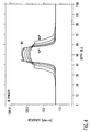
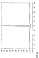
- Figure 7 shows a 1000 mS/m-20 mS/m step for ID Phasor as a function of dip angle.
- the apparent position of the boundary moves to the left (into the conductive bed) as the dip angle increases. From this behavior, it is easy to see how the apparent thickening of the resistive beds occurs.
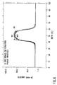
- the apparent response functions can be derived. These are shown in Fig. 8.
- Fig. 9 the response functions based on a 500 mS/m-5 mS/m step are shown. Note that the shape in the center lobes of the response functions are different from those in Fig. 8, but that the shape in the resistive part of the formation is virtually identical.
- an inverse filter is based on the linearity assumption that the measurement ⁇ m is the convolution product of the tool response g(z) with the system to be measured ⁇ F (z) where the z′ coordinate represents a position in the formation with respect to a given tool depth z.
- the convolution relationship holds accurately over a wide range of formation conductivities, since the vertical response function g(z) is constructed 7 to be independent of formation conductivity ⁇ F .
- the inverse filter for g(z) is a function h(z) such that where z and z′ have the same meaning as in equation (4).
- ⁇ (z-z′) is the Dirac delta function. If g(z) is well behaved, and its Fourier transform G(k) contains no zeroes, equation (5a) can be solved for the filter coefficients h(z) directly.
- equation (6) capital letters are used to denote Fourier transformed functions.
- G is small when spatial frequency ⁇ is large, and the result is that inverse filter H will then have the deleterious effect of amplifying noise in the absence of signal.
- Equation (5a) is solved for an inverse filter h(z) while satisfying equation (7) and the subsequent discussion.
- Equation (5a) is solved for an inverse filter h(z) while satisfying equation (7) and the subsequent discussion.
- Equation (5a) is solved for an inverse filter h(z) while satisfying equation (7) and the subsequent discussion.
- the process for developing filters for IM is identical as is the basic correction algorithm.
- dip produces on the ILM log an asymmetrical bed boundary response. Phasor processing accentuates the asymmetry.
- the dip correction filters for IM correct both the shoulder effect and the asymmetry.
- the apparent dip can be found. However, if the apparent dip of the major contrast boundaries can be readily determined from a dipmeter or FMS data, that should be used directly. If the dip angle and direction is considered one unit vector, and the deviation angle and direction is considered another, the combination of the two is just the dot product of the two unit vector.
- Equation (9) converts compass directions to polar coordinates and orients the unit vectors downwards.
- R indicates a real component of R + iX
- X is the imaginary component
- D and M indicates the deep and medium receiver array respectively
- ⁇ IIRD and ⁇ IIRM are the real components
- ⁇ IIXD is the imaginary component of the conductivity of a formation along an actual depth z at six-inch intervals.
- the input conductivities are indicated by their LIS channel names.
- the Barber patent 4,513,376 corrects the induction log for shoulder bed effects at zero dip angle.
- Equation (5) when applied to a long sequence of sampled conductivity measurements ⁇ with a filter h of length N (N odd) samples results in the filtered conductivity sequence ⁇ F where the j-th sample is where ⁇ (j-n) equals the phasor processed, converted conductivities for deep (D) and medium (M) arrays ⁇ CMPH TBT and ⁇ CDPH TBT of equation (12), and the filter h a actually comprises two values (the filter "h” for each of the two nearest defined filter angles), the filter "h” at a given apparent dip angle 'a' being derived through equation (5a) using a function of g(z) as derived from equation (B) at the given angle 'a', where angle 'a' equals two values (the two nearest defined filter angles - alpha and alpha + 10).
- the interpolation 8 is as follows
- the additional processing 9 determines the contrast at a bed boundary, and develops a small correction to be added to the results of equation (14), (16) or (19).
- ⁇ D CORR from one of these equations is filtered further where h k is one filter for ⁇ 50° and a different filter for ⁇ > 50°.
- the filter h k produces a good log at high contrast.
- the ratio of the uncorrected to the corrected conductivity is used as a measure of the contrast, and is used to form interpolation coefficients for interpolating between the output of equations (14), (16), or (19) and equation (20).
Landscapes
- Life Sciences & Earth Sciences (AREA)
- Physics & Mathematics (AREA)
- Engineering & Computer Science (AREA)
- Remote Sensing (AREA)
- Environmental & Geological Engineering (AREA)
- Geology (AREA)
- General Life Sciences & Earth Sciences (AREA)
- General Physics & Mathematics (AREA)
- Geophysics (AREA)
- Electromagnetism (AREA)
- Geophysics And Detection Of Objects (AREA)
Claims (6)
- Procédé de correction d'une diagraphie par induction, la diagraphie représentant des données mesurées de la conductivité d'une formation, obtenues par un outil à induction disposé dans un forage de formation terrestre comportant une pluralité de plans de stratification, afin de déterminer la valeur de la conductivité σF de la formation corrigée en ce qui concerne l'effet résultant de l'angle, appelé angle apparent d'inclinaison, entre l'axe longitudinal du forage et un axe perpendiculaire aux plans de stratification, le procédé comportant les étapes consistant à :
déterminer ledit angle apparent d'inclinaison,
convertir les données obtenues par ledit outil à induction en format d'épaisseur réelle de couche (TBT) en produisant ainsi les données converties en TBT, et
traiter et corriger les données converties en TBT pour réduire les effets d'une couche formant épaulement à un angle d'inclinaison pratiquement nul, en produisant par conséquent des données converties traitées,
le procédé étant caractérisé en ce qu'il consiste à :
déterminer deux filtres h(a1) et h(a2) en tant que fonction de deux angles choisis a1 et a2, où lesdits deux angles sont fonction dudit angle apparent d'inclinaison par la relation
a1 < angle apparent d'inclinaison < a2,
lesdits deux filtres h(a1) et h(a2) étant chacun déterminés en tant que fonction de leurs angles a1 et a2 conformément à l'expression


interpoler entre lesdites deux valeurs σF(a1) et σF(a2) en fonction dudit angle apparent d'inclinaison pour déterminer la valeur de σF. - Procédé selon la revendication 1, comportant en outre l'étape consistant à réaliser une correction de l'effet de peau sur la valeur déterminée de σF en utilisant l'expression


- Procédé selon la revendication 2, comportant en outre l'étape consistant à convertir en sens inverse à partir dudit format d'épaisseur de couche réelle vers un format associé auxdites données développées par ledit outil d'induction.
- Appareil pour corriger une diagraphie par induction, la diagraphie représentant les données mesurées de la conductivité d'une formation, obtenues par un outil d'induction disposé dans un forage d'une formation terrestre, comportant plusieurs plans de stratification, afin de déterminer une valeur de la conductivité σF de la formation corrigée de l'effet résultant de l'angle, appelé angle apparent d'inclinaison, existant entre l'axe longitudinal du forage et un axe perpendiculaire aux plans de stratification, l'appareil comportant :
des moyens pour déterminer ledit angle apparent d'inclinaison,
des moyens pour convertir les données obtenues par ledit outil d'induction en format d'épaisseur de couche réelle (TBT) en produisant par conséquent des données converties en TBT, et
des moyens pour traiter et corriger les données converties en TBT pour réduire les effets de couche formant épaulement au niveau d'un angle d'inclinaison à peu près nul, en produisant par conséquent des données converties traitées,
l'appareil étant caractérisé en ce qu'il comporte :
des moyens pour déterminer deux filtres h(a1) et h(a2) en tant que fonctions de deux angles choisis a1 et a2, où lesdits deux angles sont reliés audit angle apparent d'inclinaison par la relation
a1 < angle apparent d'inclinaison < a2,
lesdits deux filtres h(a1) et h(a2) étant chacun déterminés en tant que fonction de leurs angles a1 et a2 conformément à l'expression


des moyens pour interpoler entre lesdites deux valeurs σF(a1) et σF(a2) en fonction dudit angle apparent d'inclinaison pour déterminer la valeur de σF. - Appareil selon la revendication 4, comportant en outre des moyens pour réaliser une correction de l'effet de peau sur la valeur déterminée de σF en utilisant l'expression


- Appareil selon la revendication 5, comportant en outre des moyens pour convertir en sens inverse à partir dudit format d'épaisseur de couche réelle vers un format associé auxdites données développées par ledit outil d'induction.
Applications Claiming Priority (2)
| Application Number | Priority Date | Filing Date | Title |
|---|---|---|---|
| US612931 | 1990-11-13 | ||
| US07/612,931 US5184079A (en) | 1990-11-13 | 1990-11-13 | Method and apparatus for correcting data developed from a well tool disposed at a dip angle in a wellbore to eliminate the effects of the dip angle on the data |
Publications (3)
| Publication Number | Publication Date |
|---|---|
| EP0490716A2 EP0490716A2 (fr) | 1992-06-17 |
| EP0490716A3 EP0490716A3 (en) | 1993-05-12 |
| EP0490716B1 true EP0490716B1 (fr) | 1995-09-06 |
Family
ID=24455182
Family Applications (1)
| Application Number | Title | Priority Date | Filing Date |
|---|---|---|---|
| EP91403035A Expired - Lifetime EP0490716B1 (fr) | 1990-11-13 | 1991-11-13 | Procédé et dispositif pour corriger l'effet de pendage dans un mesure d'induction d'un puits et la production d'un enregistrement correspondant à cette correction |
Country Status (2)
| Country | Link |
|---|---|
| US (1) | US5184079A (fr) |
| EP (1) | EP0490716B1 (fr) |
Families Citing this family (32)
| Publication number | Priority date | Publication date | Assignee | Title |
|---|---|---|---|---|
| US5452761A (en) * | 1994-10-31 | 1995-09-26 | Western Atlas International, Inc. | Synchronized digital stacking method and application to induction logging tools |
| US5668475A (en) | 1995-12-01 | 1997-09-16 | Schlumberger Technology Corporation | Induction logging sonde including a folded array apparatus having a plurality of receiver cowound coils and bucking coils |
| US5867806A (en) * | 1996-03-13 | 1999-02-02 | Halliburton Energy Services, Inc. | System and method for performing inversion on LWD resistivity logs with enhanced resolution |
| US5774360A (en) * | 1996-03-26 | 1998-06-30 | Western Atlas International, Inc. | Method of correcting formation resistivity well logs for the effects of formation layer inclination with respect to the wellbore |
| US5781436A (en) * | 1996-07-26 | 1998-07-14 | Western Atlas International, Inc. | Method and apparatus for transverse electromagnetic induction well logging |
| US6047240A (en) * | 1998-01-16 | 2000-04-04 | Schlumberger Technology Corporation | Method and apparatus for evaluating the resistivity of invaded formations at high apparent dip angle |
| US6216089B1 (en) | 1999-09-07 | 2001-04-10 | Schlumberger Technology Corporation | Method and apparatus for producing a conductivity log unaffected by shoulder effect and dip from data developed by a well tool |
| US6304086B1 (en) | 1999-09-07 | 2001-10-16 | Schlumberger Technology Corporation | Method and apparatus for evaluating the resistivity of formations with high dip angles or high-contrast thin layers |
| US6366088B1 (en) * | 1999-12-03 | 2002-04-02 | Halliburton Energy Services, Inc. | Method to enhance vertical resolution of time-decay log using forward modeling deconvolution of time-decay spectra |
| US6885947B2 (en) * | 2001-03-08 | 2005-04-26 | Baker Hughes Incorporated | Method for joint interpretation of multi-array induction and multi-component induction measurements with joint dip angle estimation |
| US6885943B2 (en) * | 2002-09-20 | 2005-04-26 | Halliburton Energy Services, Inc. | Simultaneous resolution enhancement and dip correction of resistivity logs through nonlinear iterative deconvolution |
| US7098858B2 (en) * | 2002-09-25 | 2006-08-29 | Halliburton Energy Services, Inc. | Ruggedized multi-layer printed circuit board based downhole antenna |
| US7345487B2 (en) * | 2002-09-25 | 2008-03-18 | Halliburton Energy Services, Inc. | Method and system of controlling drilling direction using directionally sensitive resistivity readings |
| US6795774B2 (en) | 2002-10-30 | 2004-09-21 | Halliburton Energy Services, Inc. | Method for asymptotic dipping correction |
| US7814036B2 (en) * | 2003-06-19 | 2010-10-12 | Haliburton Energy Services, Inc. | Processing well logging data with neural network |
| US7027926B2 (en) * | 2004-04-19 | 2006-04-11 | Pathfinder Energy Services, Inc. | Enhanced measurement of azimuthal dependence of subterranean parameters |
| US7103982B2 (en) * | 2004-11-09 | 2006-09-12 | Pathfinder Energy Services, Inc. | Determination of borehole azimuth and the azimuthal dependence of borehole parameters |
| US7254486B2 (en) * | 2005-04-12 | 2007-08-07 | Baker Hughes Incorporated | Method and apparatus for shale bed detection in deviated and horizontal wellbores |
| US20070223822A1 (en) * | 2006-03-20 | 2007-09-27 | Pathfinder Energy Services, Inc. | Data compression method used in downhole applications |
| US7457707B2 (en) * | 2006-11-30 | 2008-11-25 | Schlumberger Technology Corporation | Method for determining an effective formation conductivity for induction log borehole correction |
| US7558675B2 (en) * | 2007-07-25 | 2009-07-07 | Smith International, Inc. | Probablistic imaging with azimuthally sensitive MWD/LWD sensors |
| WO2010024802A1 (fr) * | 2008-08-26 | 2010-03-04 | Halliburton Energy Services, Inc. | Procédé et système de traitement de courbes de décroissance du comptage de rayons gamma à l’aide de réseaux neuronaux |
| US8898045B2 (en) | 2009-04-21 | 2014-11-25 | Halliburton Energy Services, Inc. | System and method of predicting gas saturation of a formation using neural networks |
| US8195400B2 (en) * | 2009-05-08 | 2012-06-05 | Smith International, Inc. | Directional resistivity imaging using harmonic representations |
| US8271199B2 (en) * | 2009-12-31 | 2012-09-18 | Smith International, Inc. | Binning method for borehole imaging |
| US8600115B2 (en) | 2010-06-10 | 2013-12-03 | Schlumberger Technology Corporation | Borehole image reconstruction using inversion and tool spatial sensitivity functions |
| US9658360B2 (en) | 2010-12-03 | 2017-05-23 | Schlumberger Technology Corporation | High resolution LWD imaging |
| AU2013381942B2 (en) * | 2013-03-15 | 2016-06-02 | Halliburton Energy Services Inc. | Dip correction for array induction tool data |
| WO2015099773A1 (fr) * | 2013-12-27 | 2015-07-02 | Halliburton Energy Services, Inc. | Correction d'inclinaison dans des zones envahies |
| WO2015102640A1 (fr) * | 2014-01-03 | 2015-07-09 | Halliburton Energy Services, Inc. | Systèmes et procédés permettant une correction d'inclinaison relative |
| CN106837299B (zh) * | 2017-01-19 | 2019-11-19 | 中国科学院声学研究所 | 一种井眼校正的系统及方法 |
| US11143779B2 (en) * | 2018-04-16 | 2021-10-12 | Halliburton Energy Services, Inc. | Deconvolution-based enhancement of apparent resistivity and bed boundary identification in borehole resistivity imaging |
Family Cites Families (17)
| Publication number | Priority date | Publication date | Assignee | Title |
|---|---|---|---|---|
| NL132706C (fr) * | 1946-06-11 | |||
| US2582314A (en) * | 1949-06-15 | 1952-01-15 | Schlumberger Well Surv Corp | Electromagnetic well logging system |
| US2582315A (en) * | 1949-09-03 | 1952-01-15 | Schlumberger Well Surv Corp | Differential coil system for induction logging |
| US2790138A (en) * | 1955-08-09 | 1957-04-23 | Schlumberger Well Surv Corp | Induction well logging |
| US3067383A (en) * | 1959-04-16 | 1962-12-04 | Schlumberger Well Surv Corp | Induction well logging |
| US3056917A (en) * | 1959-11-30 | 1962-10-02 | Schlumberger Well Surv Corp | Methods and apparatus for investigating earth formations |
| US3147429A (en) * | 1960-02-08 | 1964-09-01 | Schlumberger Well Surv Corp | Induction method and apparatus for investigating earth formation utilizing two quadrature phase components of a detected signal |
| US3179879A (en) * | 1960-05-16 | 1965-04-20 | Schlumberger Well Surv Corp | Well logging apparatus with means for modifying one signal component by a second signal component when a predetermined condition occurs |
| US3329889A (en) * | 1962-11-28 | 1967-07-04 | Schlumberger Technology Corp | Methods and apparatus for investigating earth formations featuring simultaneous focussed coil and electrode system measurements |
| US3453530A (en) * | 1968-03-01 | 1969-07-01 | Schlumberger Technology Corp | Methods and apparatus for investigating earth formations including measuring the resistivity of radially different formation zones |
| US4472684A (en) * | 1980-07-24 | 1984-09-18 | Schlumberger Technology Corporation | Deep investigation induction logging with mirror image coil arrays |
| EG15337A (en) * | 1982-01-12 | 1993-10-30 | Schlumberger Ltd | Induction logging technique |
| US4513376A (en) * | 1982-01-12 | 1985-04-23 | Schlumberger Technology Corporation | Phasor processing of induction logs including skin effect correction |
| US4471436A (en) * | 1982-01-12 | 1984-09-11 | Schlumberger Technology Corporation | Phasor processing of induction logs including shoulder and skin effect correction |
| US4604581A (en) * | 1983-01-11 | 1986-08-05 | Halliburton Company | Method and apparatus for deconvolving apparent conductivity measurements in induction well logging |
| US4818946A (en) * | 1987-09-24 | 1989-04-04 | Schlumberger Technology Corporation | Method and apparatus for enhancing the resolution of an induction logging tool in measuring a characteristic of a borehole formation |
| US4958286A (en) * | 1988-06-27 | 1990-09-18 | Western Atlas International, Inc. | Time-variant filter coefficients |
-
1990
- 1990-11-13 US US07/612,931 patent/US5184079A/en not_active Expired - Lifetime
-
1991
- 1991-11-13 EP EP91403035A patent/EP0490716B1/fr not_active Expired - Lifetime
Non-Patent Citations (1)
| Title |
|---|
| INSPEC Conference Barcelona, 18-21 September 1990, S.CUDDY and R.PEVERARO: "Signal processing by forward modelling of the induction electrical log to determine the content of hydrocarbon reservoirs" * |
Also Published As
| Publication number | Publication date |
|---|---|
| US5184079A (en) | 1993-02-02 |
| EP0490716A3 (en) | 1993-05-12 |
| EP0490716A2 (fr) | 1992-06-17 |
Similar Documents
| Publication | Publication Date | Title |
|---|---|---|
| EP0490716B1 (fr) | Procédé et dispositif pour corriger l'effet de pendage dans un mesure d'induction d'un puits et la production d'un enregistrement correspondant à cette correction | |
| EP1328832B1 (fr) | Procede servant a determiner les resistivites apparentes de reservoirs anisotropes | |
| US6574562B2 (en) | Determination of formation anisotropy using multi-frequency processing of induction measurements with transverse induction coils | |
| US6493632B1 (en) | Water saturation and sand fraction determination from borehole resistivity imaging tool, transverse induction logging and a tensorial water saturation model | |
| US5389881A (en) | Well logging method and apparatus involving electromagnetic wave propagation providing variable depth of investigation by combining phase angle and amplitude attenuation | |
| US6636045B2 (en) | Method of determining formation anisotropy in deviated wells using separation of induction mode | |
| US7565244B2 (en) | Method and system for removing effects of conductive casings and wellbore and surface heterogeneity in electromagnetic imaging surveys | |
| US6219619B1 (en) | Inhomogeneous background-based software focusing method for array-type induction logging tools | |
| US20030105590A1 (en) | Water saturation and sand fraction determination from borehole resistivity imaging tool, transverse induction logging and a tensorial water saturation model | |
| US7991553B2 (en) | Method and system for removing effects of conductive casings and wellbore and surface heterogeneity in electromagnetic imaging surveys | |
| CA2439619C (fr) | Procede de focalisation base sur un fond non homogene permettant de mesurer l'induction de rangees dans un puits de forage devie | |
| KR890004722B1 (ko) | 유도 탐사방법 및 장치 | |
| JPH0374350B2 (fr) | ||
| Chemali et al. | The effect of shale anisotropy on focused resistivity devices | |
| Shen | Theory of a coil-type resistivity sensor for MWD application | |
| Barber et al. | Correcting the induction log for dip effect | |
| EP0872744B1 (fr) | Détermination de la conductivité des formations souterraines | |
| Rodney et al. | An MWD multiple depth of investigation electromagnetic wave resistivity sensor | |
| Faivre et al. | Dip estimation from azimuthal Laterolog tools | |
| Shen | Investigation depth of coil-type MWD resistivity sensor | |
| US4958286A (en) | Time-variant filter coefficients | |
| Cosmo et al. | Fast deconvolution of laterologs by direct inverse filtering | |
| Wu et al. | Measurement Of Dip Angle And Horizontal And Vertical Resistivities Using Multiple Frequency Propagation Resistivity Toots | |
| Ruhovets et al. | Laminated reservoir evaluation using logs with different vertical resolution | |
| Elkington et al. | RT Determination From Digital Induction Conductivity Measurements |
Legal Events
| Date | Code | Title | Description |
|---|---|---|---|
| PUAI | Public reference made under article 153(3) epc to a published international application that has entered the european phase |
Free format text: ORIGINAL CODE: 0009012 |
|
| AK | Designated contracting states |
Kind code of ref document: A2 Designated state(s): FR GB NL |
|
| PUAL | Search report despatched |
Free format text: ORIGINAL CODE: 0009013 |
|
| AK | Designated contracting states |
Kind code of ref document: A3 Designated state(s): FR GB NL |
|
| 17P | Request for examination filed |
Effective date: 19931106 |
|
| 17Q | First examination report despatched |
Effective date: 19940706 |
|
| GRAA | (expected) grant |
Free format text: ORIGINAL CODE: 0009210 |
|
| AK | Designated contracting states |
Kind code of ref document: B1 Designated state(s): FR GB NL |
|
| PG25 | Lapsed in a contracting state [announced via postgrant information from national office to epo] |
Ref country code: NL Free format text: LAPSE BECAUSE OF NON-PAYMENT OF DUE FEES Effective date: 19950906 |
|
| ET | Fr: translation filed | ||
| NLV1 | Nl: lapsed or annulled due to failure to fulfill the requirements of art. 29p and 29m of the patents act | ||
| PLBE | No opposition filed within time limit |
Free format text: ORIGINAL CODE: 0009261 |
|
| STAA | Information on the status of an ep patent application or granted ep patent |
Free format text: STATUS: NO OPPOSITION FILED WITHIN TIME LIMIT |
|
| 26N | No opposition filed | ||
| REG | Reference to a national code |
Ref country code: GB Ref legal event code: IF02 |
|
| PGFP | Annual fee paid to national office [announced via postgrant information from national office to epo] |
Ref country code: FR Payment date: 20031110 Year of fee payment: 13 |
|
| PG25 | Lapsed in a contracting state [announced via postgrant information from national office to epo] |
Ref country code: FR Free format text: LAPSE BECAUSE OF NON-PAYMENT OF DUE FEES Effective date: 20050729 |
|
| REG | Reference to a national code |
Ref country code: FR Ref legal event code: ST |
|
| PGFP | Annual fee paid to national office [announced via postgrant information from national office to epo] |
Ref country code: GB Payment date: 20081112 Year of fee payment: 18 |
|
| GBPC | Gb: european patent ceased through non-payment of renewal fee |
Effective date: 20091113 |
|
| PG25 | Lapsed in a contracting state [announced via postgrant information from national office to epo] |
Ref country code: GB Free format text: LAPSE BECAUSE OF NON-PAYMENT OF DUE FEES Effective date: 20091113 |