EP0490855A1 - Indicateur - Google Patents
Indicateur Download PDFInfo
- Publication number
- EP0490855A1 EP0490855A1 EP91850310A EP91850310A EP0490855A1 EP 0490855 A1 EP0490855 A1 EP 0490855A1 EP 91850310 A EP91850310 A EP 91850310A EP 91850310 A EP91850310 A EP 91850310A EP 0490855 A1 EP0490855 A1 EP 0490855A1
- Authority
- EP
- European Patent Office
- Prior art keywords
- pointer
- cable
- conduit
- digging arm
- conductor
- Prior art date
- Legal status (The legal status is an assumption and is not a legal conclusion. Google has not performed a legal analysis and makes no representation as to the accuracy of the status listed.)
- Granted
Links
- 239000004020 conductor Substances 0.000 claims abstract description 7
- 239000003550 marker Substances 0.000 claims 1
- 229910052751 metal Inorganic materials 0.000 description 3
- 239000002184 metal Substances 0.000 description 3
- 238000000034 method Methods 0.000 description 3
- 239000004411 aluminium Substances 0.000 description 2
- 229910052782 aluminium Inorganic materials 0.000 description 2
- XAGFODPZIPBFFR-UHFFFAOYSA-N aluminium Chemical compound [Al] XAGFODPZIPBFFR-UHFFFAOYSA-N 0.000 description 2
- XLYOFNOQVPJJNP-UHFFFAOYSA-N water Substances O XLYOFNOQVPJJNP-UHFFFAOYSA-N 0.000 description 2
- 238000009412 basement excavation Methods 0.000 description 1
- 230000006698 induction Effects 0.000 description 1
- 230000003287 optical effect Effects 0.000 description 1
- 238000010561 standard procedure Methods 0.000 description 1
Images

Classifications
-
- G—PHYSICS
- G01—MEASURING; TESTING
- G01V—GEOPHYSICS; GRAVITATIONAL MEASUREMENTS; DETECTING MASSES OR OBJECTS; TAGS
- G01V3/00—Electric or magnetic prospecting or detecting; Measuring magnetic field characteristics of the earth, e.g. declination, deviation
- G01V3/02—Electric or magnetic prospecting or detecting; Measuring magnetic field characteristics of the earth, e.g. declination, deviation operating with propagation of electric current
- G01V3/06—Electric or magnetic prospecting or detecting; Measuring magnetic field characteristics of the earth, e.g. declination, deviation operating with propagation of electric current using AC
-
- E—FIXED CONSTRUCTIONS
- E02—HYDRAULIC ENGINEERING; FOUNDATIONS; SOIL SHIFTING
- E02F—DREDGING; SOIL-SHIFTING
- E02F9/00—Component parts of dredgers or soil-shifting machines, not restricted to one of the kinds covered by groups E02F3/00 - E02F7/00
- E02F9/26—Indicating devices
Definitions
- the present invention relates to a pointer for attachment to the digging arm of a mechanical excavator or digging machine, or to some other appropriate part of said machine.
- Valuable assets are lost annually as a result of severing or destroying underground cables and underground conductors during ground excavating work carried out with the aid of excavating or digging machines.
- no effective method has been proposed which will enable the extension of underground cables, etc., to be detected and marked-out before commencing the excavation work.
- the presence of an underground cable has been localized by detecting its magnetic field in accordance with standard methods and determining the position and the geometric extension of the cable on the basis thereof. The extension of the cable is then marked with the aid of pegs driven into the ground.
- the object of the present invention is to provide a pointer which will constantly point ot or indicate the location of an underground cable during an excavating operation, so that the machine operator can avoid cutting through or digging-up the cable or conduit. This object is achieved with a pointer having the characteristic features set forth in the following Claims.
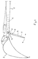
- Figure 1 illustrates schematically the inventive pointer attached to the digging arm of an excavating machine
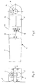
- Figure 2 illustrates schematically a detail of the invention
- Figure 3 is a schematic sectional view of the detail illustrated in Figure 2
- Figures 4 and 5 are schematic illustrations of the working method of the inventive device.
- a digging arm 2 of an excavating machine 1 carries a bucket 3 which is equipped with a pointer 4 constructed in accordance with the invention.
- the reference 5 identifies an underground cable.
- the pointer 4 has the form of an elongated arm which can be swung about an axle which extends generally at right angles to the plane of the paper, by means of a drive means.
- a receiver 6 receives and converts the signals produced by an antenna system mounted on the pointer 4, the signals received deriving from the magnetic field generated by the cable 5.
- the receiver output signals are processed in computers and are used to control drive means, in the form of a servomechanism 7, in a manner to position the pointer in the direction in which the strongest magnetic field is detected, i.e. towards the cable 5.
- control drive means in the form of a servomechanism 7, in a manner to position the pointer in the direction in which the strongest magnetic field is detected, i.e. towards the cable 5.
- the cable 5 is not current-conducting or consists of an optocable, which is normally provided with a metal screen or an aluminium strip, or when the underground object is a water pipe instead of a cable 5, there is used a transmitter for generating a magnetic field whereby an electric current can be induced in the non-conducting cable, the optocable or the water pipe, and the magnetic field generated by this current can be detected in the aforedescribed manner.
- the transmitter is preferably mounted on the excavating machine.
- Figure 1 illustrates schematically and in more detail the pointer 4 mounted on the digging arm 2 by means of an axle 9 about which the pointer can be swung or pivoted. In its upwardly swung position, its inactive position, shown in broken lines, the pointer 4 is conveniently positioned beneath a robust metal shield which protects the pointer against damage.
- the pointer of the illustrated embodiment comprises two parts, i.e. an upper part 10 which is pivotal on the axle 9, and a lower part 11 which is pivotal relative to the upper part 10 on a further axle 12, as described in more detail herebelow with reference to Figures 2 and 3.
- FIG 2 illustrates schematically the pointer 4 provided with drive means in the form of two servomotors.
- One servomotor, 13, is connected to the axle 9 through the intermediary of a worm gear 14.
- the servo motor 13 thus controls the movement of the pointer 4 on the axle 9 so as to direct the pointer constantly towards the cable 5 during the active function of the pointer.
- the pointer comprises two parts and is provided with a marking at its outer, free end.
- the end of the pointer may thus be flattened, for instance in a wedge-shape, and provided with an enlarged plate - flag - provided with a colour marking or the like, not shown, so as to obtain a direction indication.
- the axle 12 is therefore driven by a servomotor 15, through the intermediary of a gear 16, and the axle in turn rotates the lower part 11 of the pointer 4.
- the characteristics of the magnetic field generated by the cable 5 and indicating the length extension of the cable are also recorded in the receiver 6, which controls the servomotor 15 in a manner such as to rotate the lower pointer-part 11 to a position in which said marking will point to or indicate the direction of the cable.
- the invention enables the machine operator to constantly be aware of the location of an underground cable and also the length extension of said cable. This enables the machine operator to avoid digging-up the cable.
- axle 9 need not extend perpendicularly to the digging arm 2 (perpendicular to the plane of the paper in Figure 1), but may instead be inclined relative to the digging arm. The most essential factor is that the machine operator is able to clearly discern the movements made by the pointer and to see the directions in which the pointer points.
- the servo motors for effecting movement of the pointer may suitably be driven electrically or hydraulically.
Landscapes
- Engineering & Computer Science (AREA)
- Life Sciences & Earth Sciences (AREA)
- Remote Sensing (AREA)
- Physics & Mathematics (AREA)
- Structural Engineering (AREA)
- Civil Engineering (AREA)
- Environmental & Geological Engineering (AREA)
- Geology (AREA)
- Mining & Mineral Resources (AREA)
- General Engineering & Computer Science (AREA)
- General Life Sciences & Earth Sciences (AREA)
- General Physics & Mathematics (AREA)
- Geophysics (AREA)
- Geophysics And Detection Of Objects (AREA)
- Earth Drilling (AREA)
- Ink Jet (AREA)
Priority Applications (2)
| Application Number | Priority Date | Filing Date | Title |
|---|---|---|---|
| US07/916,110 US5371959A (en) | 1990-12-14 | 1991-12-11 | Pointing device carried by digging arm of excavator, for dynamically indicating location and direction of extension of underground cable |
| AT9191850310T ATE104719T1 (de) | 1990-12-14 | 1991-12-11 | Anzeiger. |
Applications Claiming Priority (2)
| Application Number | Priority Date | Filing Date | Title |
|---|---|---|---|
| SE9004002 | 1990-12-14 | ||
| SE9004002A SE467978B (sv) | 1990-12-14 | 1990-12-14 | Pekare |
Publications (2)
| Publication Number | Publication Date |
|---|---|
| EP0490855A1 true EP0490855A1 (fr) | 1992-06-17 |
| EP0490855B1 EP0490855B1 (fr) | 1994-04-20 |
Family
ID=20381200
Family Applications (1)
| Application Number | Title | Priority Date | Filing Date |
|---|---|---|---|
| EP19910850310 Expired - Lifetime EP0490855B1 (fr) | 1990-12-14 | 1991-12-11 | Indicateur |
Country Status (5)
| Country | Link |
|---|---|
| EP (1) | EP0490855B1 (fr) |
| JP (1) | JPH05504802A (fr) |
| DE (1) | DE69101774D1 (fr) |
| SE (1) | SE467978B (fr) |
| WO (1) | WO1992010619A1 (fr) |
Cited By (2)
| Publication number | Priority date | Publication date | Assignee | Title |
|---|---|---|---|---|
| WO2008064851A3 (fr) * | 2006-12-01 | 2009-10-15 | Leica Geosystems Ag | Système de localisation pour engin de terrassement |
| CN101542317B (zh) * | 2006-12-01 | 2012-11-07 | 莱卡地球系统公开股份有限公司 | 土方工程机械用的测定位置系统 |
Families Citing this family (1)
| Publication number | Priority date | Publication date | Assignee | Title |
|---|---|---|---|---|
| JP2018518654A (ja) * | 2015-03-25 | 2018-07-12 | ダニエル ルドルフ クルーゲルDaniel Rudolph Krugel | 物質を検出するための方法および装置 |
Citations (3)
| Publication number | Priority date | Publication date | Assignee | Title |
|---|---|---|---|---|
| US3858737A (en) * | 1971-12-02 | 1975-01-07 | Rikizo Senoo | Excavator |
| EP0046854A1 (fr) * | 1980-08-30 | 1982-03-10 | Friedrich Wilh. Schwing GmbH | Dispositif contrôlant le godet d'une pelle mécanique notamment du type à godet à guidage parallèle pour maintenir un angle de raclage prédéterminé |
| EP0388568A2 (fr) * | 1988-12-30 | 1990-09-26 | Compagnie Francaise De Mokta | Dispositif de mesure de la radioactivité d'une charge de minerai sur un engin d'extraction tel qu'une pelle à godet |
Family Cites Families (4)
| Publication number | Priority date | Publication date | Assignee | Title |
|---|---|---|---|---|
| DE1798258A1 (de) * | 1968-09-18 | 1971-11-04 | Utility Tool Co | Vorrichtung zur Lagebestimmung elektrisch leitender Strukturen |
| DE2312814A1 (de) * | 1973-03-15 | 1974-09-19 | Grebe Rudolf | Mit einem grabwerkzeug ausgestattete erdbewegungsmaschine, wie bagger oder dergleichen |
| US4600356A (en) * | 1984-01-27 | 1986-07-15 | Gas Research Institute | Underground pipeline and cable detector and process |
| JPS60208526A (ja) * | 1984-04-03 | 1985-10-21 | Hitachi Constr Mach Co Ltd | 掘削機の土中探索装置 |
-
1990
- 1990-12-14 SE SE9004002A patent/SE467978B/sv not_active IP Right Cessation
-
1991
- 1991-12-11 JP JP4501484A patent/JPH05504802A/ja active Pending
- 1991-12-11 EP EP19910850310 patent/EP0490855B1/fr not_active Expired - Lifetime
- 1991-12-11 WO PCT/SE1991/000852 patent/WO1992010619A1/fr not_active Ceased
- 1991-12-11 DE DE69101774T patent/DE69101774D1/de not_active Expired - Lifetime
Patent Citations (3)
| Publication number | Priority date | Publication date | Assignee | Title |
|---|---|---|---|---|
| US3858737A (en) * | 1971-12-02 | 1975-01-07 | Rikizo Senoo | Excavator |
| EP0046854A1 (fr) * | 1980-08-30 | 1982-03-10 | Friedrich Wilh. Schwing GmbH | Dispositif contrôlant le godet d'une pelle mécanique notamment du type à godet à guidage parallèle pour maintenir un angle de raclage prédéterminé |
| EP0388568A2 (fr) * | 1988-12-30 | 1990-09-26 | Compagnie Francaise De Mokta | Dispositif de mesure de la radioactivité d'une charge de minerai sur un engin d'extraction tel qu'une pelle à godet |
Cited By (4)
| Publication number | Priority date | Publication date | Assignee | Title |
|---|---|---|---|---|
| WO2008064851A3 (fr) * | 2006-12-01 | 2009-10-15 | Leica Geosystems Ag | Système de localisation pour engin de terrassement |
| AU2007324835B2 (en) * | 2006-12-01 | 2010-12-09 | Leica Geosystems Ag | Localization system for an earth moving machine |
| US8183867B2 (en) | 2006-12-01 | 2012-05-22 | Leica Geosystems Ag | Localization system for an earth moving machine |
| CN101542317B (zh) * | 2006-12-01 | 2012-11-07 | 莱卡地球系统公开股份有限公司 | 土方工程机械用的测定位置系统 |
Also Published As
| Publication number | Publication date |
|---|---|
| JPH05504802A (ja) | 1993-07-22 |
| EP0490855B1 (fr) | 1994-04-20 |
| SE467978B (sv) | 1992-10-12 |
| WO1992010619A1 (fr) | 1992-06-25 |
| SE9004002D0 (sv) | 1990-12-14 |
| DE69101774D1 (de) | 1994-05-26 |
| SE9004002L (sv) | 1992-06-15 |
Similar Documents
| Publication | Publication Date | Title |
|---|---|---|
| US5371959A (en) | Pointing device carried by digging arm of excavator, for dynamically indicating location and direction of extension of underground cable | |
| US6833795B1 (en) | Underground utility detection system and method employing ground penetrating radar | |
| EP2095156B1 (fr) | Système de localisation pour engin de terrassement | |
| KR20190034282A (ko) | 건설 기계 | |
| SE436436B (sv) | Djupmetare vid grevmaskiner | |
| US5649600A (en) | Sensor mount for an excavator | |
| US5438265A (en) | Metallic cable-locating apparatus and method having an image capturing means | |
| EP0490855B1 (fr) | Indicateur | |
| CA2093589A1 (fr) | Appareil auxiliaire pour excaver des tranchees, montable sur un godet utilise pour le terrassement | |
| JPS6389736A (ja) | 土工作業機械の高さ表示装置 | |
| US5596826A (en) | Level indicating mechanism for a work machine | |
| DE2257951A1 (de) | Schaufelbagger mit eingebautem metalldetektor | |
| US9773175B2 (en) | System and method for tracking position of cable attached to a machine | |
| JP3211574B2 (ja) | 埋設物探知方法および装置 | |
| JP3248175B2 (ja) | 埋設物探知方法および埋設物探知装置 | |
| CN114207226A (zh) | 用于检测尤其在机器作业工具附近的物体轮廓的雷达系统 | |
| JPS5910128B2 (ja) | 可撓体の水中布設方法 | |
| JPS61106894A (ja) | シ−ルド工事における切羽前方土質性状計測装置 | |
| JP2857781B2 (ja) | 路面切断用カッター装置 | |
| KR100250676B1 (ko) | 굴삭기의 굴삭깊이 측정장치 | |
| JP7173627B2 (ja) | 建設機械 | |
| JPH10152828A (ja) | ライン状地中埋設物の損傷防止装置 | |
| JPS5860208A (ja) | 掘削機械の深度測定装置 | |
| JPH08158770A (ja) | 埋設物探知装置に用いる探知刃構造 | |
| JP2019207189A (ja) | 金属探査システムおよび金属探査方法 |
Legal Events
| Date | Code | Title | Description |
|---|---|---|---|
| PUAI | Public reference made under article 153(3) epc to a published international application that has entered the european phase |
Free format text: ORIGINAL CODE: 0009012 |
|
| AK | Designated contracting states |
Kind code of ref document: A1 Designated state(s): AT BE CH DE DK ES FR GB GR IT LI LU NL SE |
|
| 17P | Request for examination filed |
Effective date: 19920703 |
|
| 17Q | First examination report despatched |
Effective date: 19930915 |
|
| GRAA | (expected) grant |
Free format text: ORIGINAL CODE: 0009210 |
|
| AK | Designated contracting states |
Kind code of ref document: B1 Designated state(s): AT BE CH DE DK ES FR GB GR IT LI LU NL SE |
|
| PG25 | Lapsed in a contracting state [announced via postgrant information from national office to epo] |
Ref country code: IT Free format text: LAPSE BECAUSE OF FAILURE TO SUBMIT A TRANSLATION OF THE DESCRIPTION OR TO PAY THE FEE WITHIN THE PRE;WARNING: LAPSES OF ITALIAN PATENTS WITH EFFECTIVE DATE BEFORE 2007 MAY HAVE OCCURRED AT ANY TIME BEFORE 2007. THE CORRECT EFFECTIVE DATE MAY BE DIFFERENT FROM THE ONE RECORDED.SCRIBED TIME-LIMIT Effective date: 19940420 Ref country code: CH Effective date: 19940420 Ref country code: DE Effective date: 19940420 Ref country code: FR Effective date: 19940420 Ref country code: BE Effective date: 19940420 Ref country code: SE Free format text: THE PATENT HAS BEEN ANNULLED BY A DECISION OF A NATIONAL AUTHORITY Effective date: 19940420 Ref country code: LI Effective date: 19940420 Ref country code: NL Effective date: 19940420 Ref country code: AT Effective date: 19940420 Ref country code: ES Free format text: THE PATENT HAS BEEN ANNULLED BY A DECISION OF A NATIONAL AUTHORITY Effective date: 19940420 Ref country code: DK Effective date: 19940420 Ref country code: GR Free format text: LAPSE BECAUSE OF FAILURE TO SUBMIT A TRANSLATION OF THE DESCRIPTION OR TO PAY THE FEE WITHIN THE PRESCRIBED TIME-LIMIT Effective date: 19940420 |
|
| REF | Corresponds to: |
Ref document number: 104719 Country of ref document: AT Date of ref document: 19940515 Kind code of ref document: T |
|
| REF | Corresponds to: |
Ref document number: 69101774 Country of ref document: DE Date of ref document: 19940526 |
|
| REG | Reference to a national code |
Ref country code: CH Ref legal event code: PL |
|
| EN | Fr: translation not filed | ||
| NLV1 | Nl: lapsed or annulled due to failure to fulfill the requirements of art. 29p and 29m of the patents act | ||
| PG25 | Lapsed in a contracting state [announced via postgrant information from national office to epo] |
Ref country code: LU Free format text: LAPSE BECAUSE OF NON-PAYMENT OF DUE FEES Effective date: 19941231 |
|
| PLBE | No opposition filed within time limit |
Free format text: ORIGINAL CODE: 0009261 |
|
| STAA | Information on the status of an ep patent application or granted ep patent |
Free format text: STATUS: NO OPPOSITION FILED WITHIN TIME LIMIT |
|
| 26N | No opposition filed | ||
| PG25 | Lapsed in a contracting state [announced via postgrant information from national office to epo] |
Ref country code: GB Effective date: 19951211 |
|
| GBPC | Gb: european patent ceased through non-payment of renewal fee |
Effective date: 19951211 |