EP0491808B1 - Procede et dispositif pour la fabrication individuelle d'une prothese dentaire - Google Patents
Procede et dispositif pour la fabrication individuelle d'une prothese dentaire Download PDFInfo
- Publication number
- EP0491808B1 EP0491808B1 EP90914051A EP90914051A EP0491808B1 EP 0491808 B1 EP0491808 B1 EP 0491808B1 EP 90914051 A EP90914051 A EP 90914051A EP 90914051 A EP90914051 A EP 90914051A EP 0491808 B1 EP0491808 B1 EP 0491808B1
- Authority
- EP
- European Patent Office
- Prior art keywords
- data
- values
- plane
- data set
- coordinates
- Prior art date
- Legal status (The legal status is an assumption and is not a legal conclusion. Google has not performed a legal analysis and makes no representation as to the accuracy of the status listed.)
- Expired - Lifetime
Links
- 238000000034 method Methods 0.000 title claims abstract description 18
- 238000004519 manufacturing process Methods 0.000 title claims abstract description 7
- 238000005259 measurement Methods 0.000 claims abstract description 18
- 230000015654 memory Effects 0.000 claims description 18
- 230000007547 defect Effects 0.000 claims description 12
- 230000001502 supplementing effect Effects 0.000 claims description 6
- 238000011156 evaluation Methods 0.000 claims description 4
- 238000012545 processing Methods 0.000 claims description 4
- 230000006870 function Effects 0.000 claims description 3
- 238000001514 detection method Methods 0.000 abstract description 4
- 238000009413 insulation Methods 0.000 description 3
- 230000003287 optical effect Effects 0.000 description 3
- 238000010276 construction Methods 0.000 description 2
- 238000011161 development Methods 0.000 description 2
- 230000018109 developmental process Effects 0.000 description 2
- 239000011159 matrix material Substances 0.000 description 2
- 238000003801 milling Methods 0.000 description 2
- 230000005855 radiation Effects 0.000 description 2
- 230000007704 transition Effects 0.000 description 2
- 230000006978 adaptation Effects 0.000 description 1
- 239000011248 coating agent Substances 0.000 description 1
- 238000000576 coating method Methods 0.000 description 1
- 230000003247 decreasing effect Effects 0.000 description 1
- 210000003298 dental enamel Anatomy 0.000 description 1
- 230000001419 dependent effect Effects 0.000 description 1
- 238000013461 design Methods 0.000 description 1
- 238000006073 displacement reaction Methods 0.000 description 1
- 230000002349 favourable effect Effects 0.000 description 1
- 239000011888 foil Substances 0.000 description 1
- 238000000227 grinding Methods 0.000 description 1
- 238000000059 patterning Methods 0.000 description 1
- 230000000737 periodic effect Effects 0.000 description 1
- 238000000053 physical method Methods 0.000 description 1
- 238000005498 polishing Methods 0.000 description 1
- 239000000843 powder Substances 0.000 description 1
- 125000006850 spacer group Chemical group 0.000 description 1
- 238000012360 testing method Methods 0.000 description 1
- 230000001960 triggered effect Effects 0.000 description 1
- 238000002604 ultrasonography Methods 0.000 description 1
- 238000004148 unit process Methods 0.000 description 1
- 230000000007 visual effect Effects 0.000 description 1
Images


Classifications
-
- A—HUMAN NECESSITIES
- A61—MEDICAL OR VETERINARY SCIENCE; HYGIENE
- A61C—DENTISTRY; APPARATUS OR METHODS FOR ORAL OR DENTAL HYGIENE
- A61C13/00—Dental prostheses; Making same
- A61C13/0003—Making bridge-work, inlays, implants or the like
- A61C13/0004—Computer-assisted sizing or machining of dental prostheses
-
- A—HUMAN NECESSITIES
- A61—MEDICAL OR VETERINARY SCIENCE; HYGIENE
- A61C—DENTISTRY; APPARATUS OR METHODS FOR ORAL OR DENTAL HYGIENE
- A61C19/00—Dental auxiliary appliances
- A61C19/04—Measuring instruments specially adapted for dentistry
-
- A—HUMAN NECESSITIES
- A61—MEDICAL OR VETERINARY SCIENCE; HYGIENE
- A61C—DENTISTRY; APPARATUS OR METHODS FOR ORAL OR DENTAL HYGIENE
- A61C5/00—Filling or capping teeth
- A61C5/70—Tooth crowns; Making thereof
- A61C5/77—Methods or devices for making crowns
-
- A—HUMAN NECESSITIES
- A61—MEDICAL OR VETERINARY SCIENCE; HYGIENE
- A61C—DENTISTRY; APPARATUS OR METHODS FOR ORAL OR DENTAL HYGIENE
- A61C9/00—Impression cups, i.e. impression trays; Impression methods
- A61C9/004—Means or methods for taking digitized impressions
- A61C9/0046—Data acquisition means or methods
- A61C9/0053—Optical means or methods, e.g. scanning the teeth by a laser or light beam
Definitions
- the invention relates to a method and a device of the type specified in the preamble of claims 1 and 6.
- a method and a device according to the first part of claims 1 and 6 are known from EP-A-0 054 785.
- the invention is based on the object of specifying a method and a device in order to improve the fitting accuracy of dentures with computer-aided means, in particular with regard to the individual bite of the patient.
- the invention is initially based on the knowledge that - in contrast to the known two-dimensional visual detection - only the three-dimensionally scanned surface of the counterbite ensures an exact fit of the bite can. From an imaginary horizontal reference plane (xy-direction), which is parallel to the bite plane, areas are determined for which the tooth surfaces of the upper and lower jaw have the same height values, i.e. if the jaw is closed, they come to lie on one another and thus the bite ( Occlusion).
- the height values of the tooth surfaces in the event that the height values of the tooth surfaces have to be determined by separate measurements in different directions, they can be adjusted by a corresponding relative shift of the height values stored in memories in association with the coordinates of the xy-plane by a lateral shift of the bite to compensate.
- the adjustment criterion is a maximization of the number of correspondingly determined height values, corresponding to a maximum area of tooth areas lying on one another when the bite is closed.
- the optimal bite position for the entire jaw is determined, which would in itself be sufficient to determine the maximum extent of the denture in the vertical direction in the area of tooth defects by decreasing the shape of the tooth surface of the opposing jaw, so that the denture also one offers exact bite shape.
- the aforementioned method does not yet offer optimal generation of an occlusion: namely, the actual bite of a patient deviates from the theoretically optimal bite.
- an arrangement is now additionally used according to the invention, which shows a flat image of the actual bite of the patient.
- electronic bite foils are known which, in areas in which a predetermined contact pressure is exceeded, each close one contact pair of a contact matrix and thus transmit an image of the actual bite to be stored in a memory to a computer scanning the intersecting matrix lines.
- this actual bite pattern is now used as a reference for the alignment of the images of the tooth surfaces of the lower and upper jaw recorded in the corresponding memories.
- the aim is to achieve a relative position of the images of the upper and lower jaw with respect to the data recorded in the memory in such a way that the corresponding height values, i.e. those values which come to lie on one another in the simulated bite present in the memory coincide with the real bite detected by means of the bite sheet, so that the stored replica of the bit assumes the position of the bit in the actual bite.
- a scanner for optically scanning the jaw region of interest is connected to a depth measuring device, the control signals for the scanner simultaneously forming address values of a measured value memory.
- a connected evaluation unit is used to determine and three-dimensional display of the surface coordinates of the measured upper and lower teeth. Occlusion and articulation are determined using a bite fork, preferably U-shaped, with a pressure-sensitive bite sheet. The contacts triggered by the tooth pressure are superimposed on the images of the upper and lower teeth. The relative position of the images of the lower jaw, the upper jaw and the bite impression can preferably be changed by mouse control, so that a clear assignment of the upper and lower jaw teeth corresponding to the occlusion can be set. In this way, missing tooth areas can also be added to the patient in terms of their existing antipodes.
- tooth areas that are not part of the occlusion stored ideal or mean value forms of corresponding size can also be used, taking into account an adapted transition.
- a subsequent computer unit processes these graphically determined superpositions into surface coordinates of the dental prosthesis part to be produced.
- contours of a similar defect-free ideal tooth or a corresponding group of teeth are used as a basis.
- the determined data are adapted to the format of the input data of a numerically controlled machine tool via a converter. This is used for automatic milling and, if necessary, for grinding and polishing the dental prosthetic item.
- At least one deflecting mirror or / and at least one prism is provided for guiding the measuring beam over the jaw region to be measured by scanning the control means.
- a double slide guide according to the principle of a plotter is preferably used for the movement.
- the control means force a certain course of movement of the deflection elements and thus a patterning of the surface. Since the control signals are uniquely assigned plane coordinates (x; y) of the projection of the measurement beam onto the tooth or jaw area to be measured, each control signal / measurement value [(x; y) / (z)] corresponds to exactly one point in space.
- the pairs of values are advantageously stored in a RAM read-only memory, the control signals forming the address values. This is the prerequisite for convenient further processing of the data.
- the distance measured values are essentially determined using known optical methods, for example the triangulation method or the dynamic focusing method. Accordingly, the measuring beam is a laser beam or a light beam, the wavelength of which is preferably in the infrared range.
- a photodetector arrangement, but also a CCD target, is particularly suitable as the photoelectric receiver.
- the scanning device shown in FIG. 1 essentially consists of two parallel guides in the form of rails 1 and 2, which are rigidly connected to one another by struts 3 and 4 in the form of spacers, a carriage which can move on the rails 1 and 2 and form a traverse 5 and a movable on this traverse runner 6, which is perpendicular to the carriage 5 is displaceable to the course of the rails 1 and 2. Due to its own displaceability on the carriage 5 and the displaceability of the carriage 5, the traverse 6 can reach any point on a plane spanned between the rails 1 and 2.
- Both the radiation source and the receiver of the measuring beam 8 are connected in a common housing to a measuring unit 10 located on the rotor element 6 via a beam guide channel 7, which is firmly connected to the rotor 6 and has approximately the length of a rail 1 or 2.
- the radiation source and receiver are consequently moved with the rotor.
- the measuring unit 10 forms a complete distance measuring device which determines the distance of an obstacle located below the measuring unit and outputs a signal which is representative of this distance related to a point of the runner.
- a system operating according to the principle of dynamic focusing as it corresponds to the scanner of a CD player, it is dynamically tracked and the position information that results when focusing is transmitted as a measured distance value.
- FIG. 1 shows two different positions of the measuring arrangement moved with carriage 5 and rotor 6.
- the carriage 5 and the runner 6 can be driven, for example, by stepper motors 11 and 12, the drivers 13 and 14 of which respectively set a spindle-shaped worm 15 or 16 adapted to the length of the rail or the carriage in rotation, the carriage 5 and the rotor 6 engage with the racks 15 and 16 by means of toothed racks and are thereby moved.
- the voltage profiles of the control voltages for the motors 11 and 12, which are assigned to the x / y values to be set for the respective position to be maintained, are supplied by an external module 17 and in the form of coded control signals 17a (x-position) and 17b (y -Position) supplied coded so that they can advantageously simultaneously form the address values for later storage of the measured values determined (z position), which are obtained at the output 17c.
- the rotor 6 with the measuring system 10 and the crossbar of the carriage 5 corresponds in its design to the guidance of a scanner in a conventional CD player, so that the corresponding miniaturized components available on the market can largely be used in the construction.
- the distance can also be scanned using other physical methods, which is to be called the triangulation. Such methods are also favorable which generate an echo signal, the delay of which permits conclusions to be drawn about the depth distance and which operate, for example, by means of ultrasound or a microwave.
- FIG. 2 shows an assembly overview for processing measured values for the automatic production of a tooth replacement part, in particular a crown or a bridge, taking into account the occlusion and the articulation.
- a scanning device 18, for example based on the type shown in Figure 1 is controlled by an external controller 19 such that the Measuring beam is guided with a certain movement over the tooth area to be measured. A unique point of the scanning level is assigned to each control signal.
- the controller 19 is connected via a coding device 20 to the address input 21 of a RAM read-only memory 22, while the measurement signals go directly to the assigned memory locations 24 via a measurement value determination 23.
- a computer 25 connected to the memory 22 processes the determined and stored surface coordinates of the upper jaw area and the associated lower jaw area, as a result of which both areas can be displayed as three-dimensional graphics on a connected monitor 26.
- a U-shaped bite fork 27 made of pressure-sensitive film, which is used to determine the terminal occlusion and the articulation.
- the pressure points or pressure zones determined are displayed on the monitor 26 on the same scale as the upper and lower jaw areas.
- the surface of the bite fork 27 has been immersed in a wax bath for better positioning in the mouth.
- the bite fork 27 can be sterilized without problems using a steam jet and / or thermal disinfector or in the customary sterilizers. Coating with a new wax layer is also possible without great effort.
- the image of the bite fork 27 is brought into alignment with the corresponding points of the lower jaw image and the upper jaw image via a mouse control 28.
- An evaluation unit 29 for determining the contours of the dental prosthetic item to be manufactured is connected to the computer 25 as well as to the monitor 26 and the memory 22, the monitor graphics being a clear one Assignment of the upper and lower jaw is reproduced in such a way that the contours to be determined fit into the given occlusion or articulation.
- the data of a defect-free ideal tooth or ideal tooth area contained in the memory 22 are used to complete the missing boundary surfaces of the dental prosthesis.
- the output data of the evaluation unit 29 characterize a measured negative impression of a tooth defect or a tooth gap, which was completed according to dentological aspects, taking into account the occlusion and the articulation, in such a way that the outlines of the dental prosthesis to be produced are thus given.
- These data are fed to a converter for adaptation to the format of the input data of a numerically controlled machine tool and are then used to control the machine tool 31, in particular a milling machine, which mills the dental prosthetic item out of a blank in an individually suitable form.
- a control unit (19) for, in particular scanning, guiding the measuring beam (8) and generating three-dimensional images of mutually facing regions of the upper and lower jaw by point-by-point scanning a measured value memory (22) for storing the images of the lower and Upper jaw in the form of individual measured value data corresponding to the measurement points as the first data record, a pressure-sensitive bite sheet (27), a unit for two-dimensional detection of areas of the bite sheet in which a predetermined contact pressure is exceeded during a test bite of the patient, and storage of these coordinate values as data in a second data set
- a computer unit (25) for determining areas in which the vertical components, taking into account the horizontal reference planes for the measured values separately recorded for the upper and lower jaw and the different measuring direction a control unit (19) for, in particular scanning, guiding the measuring beam (8) and generating three-dimensional images of mutually facing regions of the upper and lower jaw by point-by-point scanning, a measured value memory (22) for storing the images of the lower and Upper jaw in the form of individual measured value data
- missing areas can be supplemented according to the individual bite.
- the areas between the occlusions and the remaining tooth areas are optimally adapted to the transition areas added to existing (saved) tooth samples.
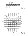
- FIGS. 3a An exemplary embodiment for the construction of a pressure-sensitive film is shown in FIGS. 3a in a sectional view and 3b in a plan view.
- the film essentially consists of two layers of crossed wires, 32 and 33, which are separated from one another by a rubber-like insulation layer 34, the insulation layer each having a hole 35 at the crossing points of the wires.
- the rubber-like insulation layer When pressure is exerted on the point 36, for example, the rubber-like insulation layer is pressed together so that the wires 37 of the layer 32 and 38 of the layer 33 touch within the hole 39. This closes a contact that irreversibly sets an electrical element of a circuit, not shown, in another state. In this way, each pressure point can be registered and displayed at any time on a monitor.
Landscapes
- Health & Medical Sciences (AREA)
- Life Sciences & Earth Sciences (AREA)
- General Health & Medical Sciences (AREA)
- Epidemiology (AREA)
- Dentistry (AREA)
- Animal Behavior & Ethology (AREA)
- Oral & Maxillofacial Surgery (AREA)
- Public Health (AREA)
- Veterinary Medicine (AREA)
- Physics & Mathematics (AREA)
- Optics & Photonics (AREA)
- Engineering & Computer Science (AREA)
- Biomedical Technology (AREA)
- Biophysics (AREA)
- Dental Tools And Instruments Or Auxiliary Dental Instruments (AREA)
Abstract
Claims (16)
- Procédé pour la fabrication individuelle d'une prothèse dentaire, en particulier d'une couronne ou d'une partie de dentition, avec utilisation d'un système de détection ce défauts de dentition et d'une machine-outil à commande numérique, les signaux de commande pour la machine-outil étant tirés, avec assistance par ordinateur, du défaut de dentition relevé ou mésuré, caractérisé par les étapes de procédé consistant à:
guider un faisceau de mesure (8) sur une région dentaire à relever et produire chaque fois une représentation tridimensionnelle de régions dentaires dirigées l'une vers l'autre des maxillaires supérieur et inférieur par exploration ponctuelle des coordonnées du plan d'occlusion (plan xy) ou d'un plan de référénce parallèle au plan d'occlusion, ainsi qu'à déterminer les valeurs de hauteur (z ou suivant la direction z) coordonnées aux valeurs de coordonnées x, y,
mémoriser les représentations tridimensionnelles des maxillaires inférieur et supérieur sous la forme de valeurs de hauteur individuelles, correspondant aux coordonnnées x, y, comme premières et deuxièmes données partielles respectivement d'un premier ensemble de données,
explorer suivant deux dimensions des régions dans lesquelles, lors d'une prise d'empreinte du patient, une pression de contact préfixée est dépassée, et mémoriser les valeurs de coordonnées du plan d'occlusion (plan xy) associées à ces régions comme deuxième ensemble de données,
déterminer des régions du plan d'occlusion (plan xy) dans lesquelles les valeurs de hauteur (z ou suivant la direction z) des premières et deuxièmes données partielles du premier ensemble de données, en tenant compte de la direction de mesure utilisée à chaque fois, pour des valeurs de coordonnées x, y identiques, concordent, et mémoriser les valeurs de coordonnées du plan d'occlusion associées à ces régions comme troisième ensemble de données,
superposer autant que possible les données du deuxième et du troisième ensemble de données, de manière que les valeurs du deuxième ensemble coïncident autant que possible complètement avec les valeurs du troisième ensemble de données, en particulier en changeant les coordonnées du plan d'occlusion pour tous les points du deuxième ensemble par rapport aux coordonnées du troisième ensemble de données, les coordonnées des points pour lesquels, après la superposition, les valeurs du deuxième et du troisième ensemble de données coïncident, formant un quatrième ensemble de données, ainsi qu'à compléter des valeurs de hauteur (z ou suivant la direction z) manquantes dans le maxillaire supérieur ou inférieur, dans la région de défauts de dentition, par les valeurs de hauteur correspondantes, pour les coordonnées x, y concernées dans cette région, du maxillaire antagoniste du premier ensemble de données, et mémoriser les valeurs de coordonnées comme cinquième ensemble de données, les valeurs de hauteur se rapportant au plan d'occlusion (plan xy). - Procédé selon la revendication 1, caractérisé par l'introduction des coordonnées d'une région du plan d'occlusion dans laquelle existe un défaut de dentition, au moins comme partie du cinquième ensemble de données.
- Procédé selon la revendication 1 ou 2, caractérisé en ce que les valeurs des deuxième, troisième, quatrième et/ou cinquième ensembles de données sont mémorisées comme des valeurs logiques et sont mises en corrélation, pendant le traitement, par des combinaisons logiques ET.
- Procédé selon une des revendications 1 à 3, caractérisé en ce que, lors de la superposition de données du deuxième et du troisième ensemble de données, plusieurs troisièmes ensembles de données, produits pour différentes positions relatives des maxillaires supérieur et inférieur, sont comparés l'un après l'autre avec le deuxième ensemble de données, avec sélection, comme quatrième ensemble de données, de celui des troisièmes ensembles de données présentant la concordance maximale des données avec celle du deuxième ensemble.
- Procédé selon une des revendications 2 à 4, caractérisé par le complètement de valeurs de coordonnées pour des régions du plan d'occlusion, dans lesquelles existe un défaut de dentition, valeurs de coordonnées qui forment un cinquième ensemble de données, par les valeurs de coordonnées d'un modèle de dentition contenue dans un mémoire de modèles, valeurs qui forment un sixième ensemble de données, avec raccordement continu aux valeurs de hauteur mesurées et traitées.
- Dispositif pour la mise en oeuvre du procédé selon une des revendications précédentes, caractérisé par
un dispositif de mesure avec une unité de pilotage (19) pour guider, en particulier avec balayage, un faisceau de mesure (8) sur une région dentaire à relever et pour produire chaque fois une représentation tridimensionnelle de régions dentaires dirigées l'une vers l'autre des maxillaires supérieur et inférieur par exploration ponctuelle des coordonnées du plan d'occlusion (plan xy) ou d'un plan de référence parallèle au plan d'occlusion, ainsi que pour déterminer les valeurs de hauteur coordonnées (z ou suivant la direction z),
une mémoire de valeurs mesurées (22) pour stocker les représentations tridimensionnelles des maxillaires inférieur et supérieur sous la forme de coordonnées individuelles, correspondant aux points de mesure, respectivement comme des premières et des deuxièmes données partielles d'un premier ensemble de données, un dispositif (27) déterminant la pression de la dentition dans le plan de l'occlusion,
une unité pour la détermination bidimensionnelle de régions du dispositif de détermination de la pression de la dentition dans lesquelles une pression de contact préfixée est dépassée lors d'une prise d'empreinte du patient, et la mémorisation des résultats en fonction des valeurs de coordonnées y, x associées du plan d'occlusion (plan xy) comme deuxième ensemble de données,
une unité de calculateur (25) pour déterminer des régions du plan d'occlusion (plan xy) dans lesquelles les valeurs de hauteur (z ou suivant la direction z) des premières et deuxièmes données partielles du premier ensemble de données, se rapportant respectivement au maxillaire supérieur et au maxillaire inférieur, en tenant compte de la direction de mesure utilisée à chaque fois, concordent pour des valeurs de coordonnées x, y identiques, et pour mémoriser les résultats en fonction des valeurs de coordonnées associées du plan d'occlusion comme au moins un troisième exemple de données dans la mémoire de valeurs mésurées,
une unité d'égalisation pour superposer au moins autant que possible les données du deuxième et du troisième ensemble de données, les valeurs de coordonnées du deuxième ensemble devant coïncider autant que possible complètement avec les valeurs de coordonnées du troisième ensemble, en particulier par le changement des coordonnées x, y du plan d'occlusion pour tous les points du deuxième ensemble par rapport aux coordonnées x, y du troisième ensemble de données, ainsi que
une unité pour compléter des valeurs de hauteur dans le maxillaire supérieur ou inférieur, dans la région de défauts de dentition, par les valeurs de hauteur déterminées dans cette région pour les coordonnées x, y concernées du maxillaire antagoniste du premier ensemble de données, comme cinquième ensemble de données, les valeurs de hauteur se rapportant au plan d'occlusion. - Dispositif selon la revendication 6, caractérisé par la prévision d'un dispositif d'entrée pour l'introduction d'une région de coordonnées du plan d'occlusion dans laquelle existe un défaut de dentition.
- Dispositif selon la revendication 7, caractérisé en ce que l'unité d'égalisation et/ou l'unité pour compléter possèdent des moyens pour la combinaison logique ET des valeurs des deuxième, troisième, quatrième et/ou cinquième ensembles de données comme valeurs logiques mémorisées.
- Dispositif selon une des revendications 6 à 8, caractérisé par un dispositif d'approximation pour compléter des valeurs de hauteur dans des régions du plan d'occlusion dans lesquelles existe un défaut de dentition, par des valeurs de hauteur correspondantes d'un modèle de dentition contenu dans une mémoire de modèles, avec raccordement continu aux valeurs de hauteur complétées.
- Dispositif selon une des revendications 6 à 9, caractérisé par un laser pour générer le faisceau de mesure (8).
- Dispositif selon une des revendications 6 à 9, caractérisé en ce que la longueur d'onde du faisceau de mesure (8) est comprise dans le domaine infrarouge.
- Dispositif selon une des revendications 6 à 11, caractérisé en ce que des photodétecteurs suivis d'un circuit d'amplification différentielle sont prévus comme récepteur et pour déterminer les valeurs mesurées.
- Dispositif selon une des revendications 6 à 11, caractérisé en ce qu'une cible à couplage de charge est prévue comme récepteur.
- Dispositif selon une des revendication 6 à 13, caractérisé en ce que le dispositif pour déterminer la pression de la dentition est une feuille d'occlusion (27) sensible à la pression.
- Dispositif selon la revendication 14, caractérisé en ce que la feuille d'occlusion (27) sensible à la pression est réalisée comme une fourchette d'occlusion en forme de U.
- Dispositif selon une des revendications précédentes, caractérisé par une commande par souris (28) et un visuel, la position relative des représentations, sous forme d'ensembles de données, pouvant être changée à l'aide de la commande par souris (28) et l'évaluation de l'égalisation produite s'effectuant au moyen d'un visuel qui présente les ensembles de données chaque fois dans une représentation à superposition.
Applications Claiming Priority (2)
| Application Number | Priority Date | Filing Date | Title |
|---|---|---|---|
| DE3932149 | 1989-09-22 | ||
| DE3932149 | 1989-09-22 |
Publications (2)
| Publication Number | Publication Date |
|---|---|
| EP0491808A1 EP0491808A1 (fr) | 1992-07-01 |
| EP0491808B1 true EP0491808B1 (fr) | 1993-09-01 |
Family
ID=6390246
Family Applications (1)
| Application Number | Title | Priority Date | Filing Date |
|---|---|---|---|
| EP90914051A Expired - Lifetime EP0491808B1 (fr) | 1989-09-22 | 1990-09-24 | Procede et dispositif pour la fabrication individuelle d'une prothese dentaire |
Country Status (5)
| Country | Link |
|---|---|
| EP (1) | EP0491808B1 (fr) |
| AU (1) | AU6435590A (fr) |
| DE (3) | DE4091623D2 (fr) |
| ES (1) | ES2043387T3 (fr) |
| WO (1) | WO1991003989A1 (fr) |
Families Citing this family (3)
| Publication number | Priority date | Publication date | Assignee | Title |
|---|---|---|---|---|
| US5273429A (en) * | 1992-04-03 | 1993-12-28 | Foster-Miller, Inc. | Method and apparatus for modeling a dental prosthesis |
| DE4214876C2 (de) * | 1992-05-05 | 2000-07-06 | Kaltenbach & Voigt | Optische Vermessungen von Zähnen ohne mattierende Oberflächenbehandlung |
| US9408686B1 (en) | 2012-01-20 | 2016-08-09 | Conformis, Inc. | Devices, systems and methods for manufacturing orthopedic implants |
Family Cites Families (4)
| Publication number | Priority date | Publication date | Assignee | Title |
|---|---|---|---|---|
| DE3171266D1 (en) * | 1980-12-24 | 1985-08-08 | Mormann Werner H | Process for the manufacture of medical and dental, alloplastic, endoprosthetic and exoprosthetic fittings |
| FR2525103B1 (fr) * | 1982-04-14 | 1985-09-27 | Duret Francois | Dispositif de prise d'empreinte par des moyens optiques, notamment en vue de la realisation automatique de protheses |
| US4663720A (en) * | 1984-02-21 | 1987-05-05 | Francois Duret | Method of and apparatus for making a prosthesis, especially a dental prosthesis |
| US4734034A (en) * | 1985-03-29 | 1988-03-29 | Sentek, Incorporated | Contact sensor for measuring dental occlusion |
-
1990
- 1990-09-24 EP EP90914051A patent/EP0491808B1/fr not_active Expired - Lifetime
- 1990-09-24 DE DE90DE9000729D patent/DE4091623D2/de not_active Expired - Lifetime
- 1990-09-24 DE DE19904091623 patent/DE4091623A1/de not_active Withdrawn
- 1990-09-24 ES ES90914051T patent/ES2043387T3/es not_active Expired - Lifetime
- 1990-09-24 DE DE90914051T patent/DE59002586D1/de not_active Expired - Lifetime
- 1990-09-24 AU AU64355/90A patent/AU6435590A/en not_active Abandoned
- 1990-09-24 WO PCT/DE1990/000729 patent/WO1991003989A1/fr not_active Ceased
Also Published As
| Publication number | Publication date |
|---|---|
| DE59002586D1 (de) | 1993-10-07 |
| AU6435590A (en) | 1991-04-18 |
| WO1991003989A1 (fr) | 1991-04-04 |
| DE4091623A1 (en) | 1992-10-08 |
| DE4091623D2 (en) | 1992-10-08 |
| ES2043387T3 (es) | 1993-12-16 |
| EP0491808A1 (fr) | 1992-07-01 |
Similar Documents
| Publication | Publication Date | Title |
|---|---|---|
| DE60218386T2 (de) | Verfahren und System zur Erstellung eines dentalen Modells mittels Bildgebung | |
| DE69521115T2 (de) | Verfahren und vorrichtung für ein produkt , vorgesehen um in den menschlichen körper eingeführt zu werden | |
| DE3723555C2 (de) | Verfahren zur Herstellung von Zahnersatz | |
| DE69413852T2 (de) | Verfahren zur Herstellung einer Prothese die auf im Kieferknochen eines Patienten fixierten Implantaten befestigt wird, und Vorrichtung zur Herstellung derartigen Prothesen | |
| EP1762821B1 (fr) | Dispositif et procédé destinés à la fabrication d'éléments de remplacement de dents | |
| EP2039321B1 (fr) | Détermination et production de surface | |
| DE68926814T2 (de) | Gerät zur Digitalisierung der Kontur der Fläche eines Zahnes, insbesondere verwendbar bei der Herstellung einer Zahnkrone | |
| DE3877976T2 (de) | Verfahren und vorrichtung zum erstellen eines abdrucks fuer medizinische zwecke. | |
| DE69413204T2 (de) | Verfahren und vorrichtung zum sammeln von daten für die herstellung von künstlichen stützelementen oder austauschteilen für den menschlichen körper | |
| DE3312245A1 (de) | Geraet zur diagnose von unterkieferbewegungen | |
| EP1406555B1 (fr) | Procede et dispositif pour mesurer et numeriser en trois dimensions un modele dentaire | |
| WO1991003980A1 (fr) | Dispositif pour l'exploration d'une region de la cavite buccale | |
| DE10355384A1 (de) | Verfahren und Vorrichtung zum Ausrichten einer Röntgenstrahlquelle und eines Detektors bei verschiedenen Abständen zwischen Quelle und Bild | |
| EP0572798A2 (fr) | Dispositif pour la mesure sans contact d'un objet tridimensionnel | |
| EP0250993A2 (fr) | Méthode et appareil pour déterminer et représenter la forme de dents (d'une dent ) taillée(s) en trois dimensions. | |
| EP2457058B1 (fr) | Production d'un ensemble de données globales | |
| CH688471A5 (de) | Gravierer und Verfahren zu dessen Betrieb | |
| EP1105067A1 (fr) | Procede de fabrication de prothese dentaire pilote par ordinateur | |
| EP0447531B1 (fr) | Procede et dispositif pour le mesurage optique tridimensionnel de corps, notamment de dents, dans la cavite buccale d'un patient | |
| DE3810455A1 (de) | Verfahren und vorrichtung zur beruehrungsfreien raeumlichen erfassung eines unregelmaessigen koerpers | |
| EP0455855B1 (fr) | Procédé et dispositif pour fabriquer des prothèses médicales en particulier dentaires | |
| EP0491808B1 (fr) | Procede et dispositif pour la fabrication individuelle d'une prothese dentaire | |
| EP3195826B1 (fr) | Procédé de production d'un modèle dentaire numérique | |
| EP1710536B1 (fr) | Procédé de saisie tridimensionnelle de la forme d'un objet | |
| DE68904205T2 (de) | Verfahren zum digitalisieren der oberflaeche eines dreidimensionalen gegenstandes und aufnahmevorrichtung zur anwendung dieses verfahrens. |
Legal Events
| Date | Code | Title | Description |
|---|---|---|---|
| PUAI | Public reference made under article 153(3) epc to a published international application that has entered the european phase |
Free format text: ORIGINAL CODE: 0009012 |
|
| 17P | Request for examination filed |
Effective date: 19920422 |
|
| AK | Designated contracting states |
Kind code of ref document: A1 Designated state(s): CH DE ES FR GB IT LI |
|
| 17Q | First examination report despatched |
Effective date: 19921229 |
|
| GRAA | (expected) grant |
Free format text: ORIGINAL CODE: 0009210 |
|
| AK | Designated contracting states |
Kind code of ref document: B1 Designated state(s): CH DE ES FR GB IT LI |
|
| REF | Corresponds to: |
Ref document number: 59002586 Country of ref document: DE Date of ref document: 19931007 |
|
| ITF | It: translation for a ep patent filed | ||
| REG | Reference to a national code |
Ref country code: ES Ref legal event code: FG2A Ref document number: 2043387 Country of ref document: ES Kind code of ref document: T3 |
|
| ET | Fr: translation filed | ||
| GBT | Gb: translation of ep patent filed (gb section 77(6)(a)/1977) |
Effective date: 19931201 |
|
| PLBE | No opposition filed within time limit |
Free format text: ORIGINAL CODE: 0009261 |
|
| STAA | Information on the status of an ep patent application or granted ep patent |
Free format text: STATUS: NO OPPOSITION FILED WITHIN TIME LIMIT |
|
| 26N | No opposition filed | ||
| REG | Reference to a national code |
Ref country code: GB Ref legal event code: IF02 |
|
| PGFP | Annual fee paid to national office [announced via postgrant information from national office to epo] |
Ref country code: ES Payment date: 20090928 Year of fee payment: 20 |
|
| PGFP | Annual fee paid to national office [announced via postgrant information from national office to epo] |
Ref country code: GB Payment date: 20090922 Year of fee payment: 20 Ref country code: CH Payment date: 20090923 Year of fee payment: 20 |
|
| PGFP | Annual fee paid to national office [announced via postgrant information from national office to epo] |
Ref country code: DE Payment date: 20091002 Year of fee payment: 20 |
|
| PGFP | Annual fee paid to national office [announced via postgrant information from national office to epo] |
Ref country code: IT Payment date: 20090924 Year of fee payment: 20 |
|
| REG | Reference to a national code |
Ref country code: CH Ref legal event code: PL |
|
| REG | Reference to a national code |
Ref country code: GB Ref legal event code: PE20 Expiry date: 20100923 |
|
| PG25 | Lapsed in a contracting state [announced via postgrant information from national office to epo] |
Ref country code: GB Free format text: LAPSE BECAUSE OF EXPIRATION OF PROTECTION Effective date: 20100923 |
|
| PGFP | Annual fee paid to national office [announced via postgrant information from national office to epo] |
Ref country code: FR Payment date: 20091005 Year of fee payment: 20 |
|
| REG | Reference to a national code |
Ref country code: ES Ref legal event code: FD2A Effective date: 20120510 |
|
| PG25 | Lapsed in a contracting state [announced via postgrant information from national office to epo] |
Ref country code: ES Free format text: LAPSE BECAUSE OF EXPIRATION OF PROTECTION Effective date: 20100925 |
|
| PG25 | Lapsed in a contracting state [announced via postgrant information from national office to epo] |
Ref country code: DE Free format text: LAPSE BECAUSE OF EXPIRATION OF PROTECTION Effective date: 20100924 |