EP0492014B1 - Appareil automatique pour abraser - Google Patents
Appareil automatique pour abraser Download PDFInfo
- Publication number
- EP0492014B1 EP0492014B1 EP90314389A EP90314389A EP0492014B1 EP 0492014 B1 EP0492014 B1 EP 0492014B1 EP 90314389 A EP90314389 A EP 90314389A EP 90314389 A EP90314389 A EP 90314389A EP 0492014 B1 EP0492014 B1 EP 0492014B1
- Authority
- EP
- European Patent Office
- Prior art keywords
- grinding
- motor
- sliding device
- disk
- grinder
- Prior art date
- Legal status (The legal status is an assumption and is not a legal conclusion. Google has not performed a legal analysis and makes no representation as to the accuracy of the status listed.)
- Expired - Lifetime
Links
Images


Classifications
-
- G—PHYSICS
- G05—CONTROLLING; REGULATING
- G05B—CONTROL OR REGULATING SYSTEMS IN GENERAL; FUNCTIONAL ELEMENTS OF SUCH SYSTEMS; MONITORING OR TESTING ARRANGEMENTS FOR SUCH SYSTEMS OR ELEMENTS
- G05B19/00—Program-control systems
- G05B19/02—Program-control systems electric
- G05B19/18—Numerical control [NC], i.e. automatically operating machines, in particular machine tools, e.g. in a manufacturing environment, so as to execute positioning, movement or co-ordinated operations by means of program data in numerical form
- G05B19/416—Numerical control [NC], i.e. automatically operating machines, in particular machine tools, e.g. in a manufacturing environment, so as to execute positioning, movement or co-ordinated operations by means of program data in numerical form characterised by control of velocity, acceleration or deceleration
- G05B19/4163—Adaptive control of feed or cutting velocity
-
- B—PERFORMING OPERATIONS; TRANSPORTING
- B25—HAND TOOLS; PORTABLE POWER-DRIVEN TOOLS; MANIPULATORS
- B25J—MANIPULATORS; CHAMBERS PROVIDED WITH MANIPULATION DEVICES
- B25J11/00—Manipulators not otherwise provided for
- B25J11/005—Manipulators for mechanical processing tasks
- B25J11/0065—Polishing or grinding
-
- B—PERFORMING OPERATIONS; TRANSPORTING
- B25—HAND TOOLS; PORTABLE POWER-DRIVEN TOOLS; MANIPULATORS
- B25J—MANIPULATORS; CHAMBERS PROVIDED WITH MANIPULATION DEVICES
- B25J9/00—Program-controlled manipulators
- B25J9/16—Program controls
- B25J9/1679—Program controls characterised by the tasks executed
- B25J9/1684—Tracking a line or surface by means of sensors
-
- G—PHYSICS
- G05—CONTROLLING; REGULATING
- G05B—CONTROL OR REGULATING SYSTEMS IN GENERAL; FUNCTIONAL ELEMENTS OF SUCH SYSTEMS; MONITORING OR TESTING ARRANGEMENTS FOR SUCH SYSTEMS OR ELEMENTS
- G05B2219/00—Program-control systems
- G05B2219/30—Nc systems
- G05B2219/37—Measurements
- G05B2219/37285—Load, current taken by motor
-
- G—PHYSICS
- G05—CONTROLLING; REGULATING
- G05B—CONTROL OR REGULATING SYSTEMS IN GENERAL; FUNCTIONAL ELEMENTS OF SUCH SYSTEMS; MONITORING OR TESTING ARRANGEMENTS FOR SUCH SYSTEMS OR ELEMENTS
- G05B2219/00—Program-control systems
- G05B2219/30—Nc systems
- G05B2219/37—Measurements
- G05B2219/37405—Contact detection between workpiece and tool, probe, feeler
-
- G—PHYSICS
- G05—CONTROLLING; REGULATING
- G05B—CONTROL OR REGULATING SYSTEMS IN GENERAL; FUNCTIONAL ELEMENTS OF SUCH SYSTEMS; MONITORING OR TESTING ARRANGEMENTS FOR SUCH SYSTEMS OR ELEMENTS
- G05B2219/00—Program-control systems
- G05B2219/30—Nc systems
- G05B2219/45—Nc applications
- G05B2219/45058—Grinding, polishing robot
-
- G—PHYSICS
- G05—CONTROLLING; REGULATING
- G05B—CONTROL OR REGULATING SYSTEMS IN GENERAL; FUNCTIONAL ELEMENTS OF SUCH SYSTEMS; MONITORING OR TESTING ARRANGEMENTS FOR SUCH SYSTEMS OR ELEMENTS
- G05B2219/00—Program-control systems
- G05B2219/30—Nc systems
- G05B2219/49—Nc machine tool, till multiple
- G05B2219/49362—Tool, probe at constant height to surface during machining
-
- G—PHYSICS
- G05—CONTROLLING; REGULATING
- G05B—CONTROL OR REGULATING SYSTEMS IN GENERAL; FUNCTIONAL ELEMENTS OF SUCH SYSTEMS; MONITORING OR TESTING ARRANGEMENTS FOR SUCH SYSTEMS OR ELEMENTS
- G05B2219/00—Program-control systems
- G05B2219/30—Nc systems
- G05B2219/50—Machine tool, machine tool null till machine tool work handling
- G05B2219/50109—Soft approach, engage, retract, escape, withdraw path for tool to workpiece
-
- G—PHYSICS
- G05—CONTROLLING; REGULATING
- G05B—CONTROL OR REGULATING SYSTEMS IN GENERAL; FUNCTIONAL ELEMENTS OF SUCH SYSTEMS; MONITORING OR TESTING ARRANGEMENTS FOR SUCH SYSTEMS OR ELEMENTS
- G05B2219/00—Program-control systems
- G05B2219/30—Nc systems
- G05B2219/50—Machine tool, machine tool null till machine tool work handling
- G05B2219/50113—Short stroke, retract tool, safe distance from workpiece surface, hover height
Definitions
- This invention relates to an automatic grinding apparatus used for finishing a work piece by removing excess weld metal, deburring or chamferring.
- the apparatus comprises an electronic grinder whose motor load current decreases or increases due to the metal removal quantity per unit hour, a slider supporting the grinder, a sliding device elevating the slider, a travelling truck and rails.
- the travelling truck runs parallel to the grinding line (of the excess weld metal or weld reinforcement) on the rails at a constant speed.
- a pinion projects from the bottom of the travelling truck to engage a rack provided on the guide rails.
- a travelling motor which is contained in the travelling device, rotates the pinion through a speed reduction device to move the truck along the longitudinal direction of the rails at a constant speed.
- the sliding device controls the perpendicular distance between the electronic grinder and the excess metal welding.
- a supporting block contained in the slider is threaded to engage an output shaft of the slide elevation motor which is provided at the upper end of the device to elevate the slider by rotation of the elevation motor.
- the electronic grinder is attached by a holder provided at the front portion of the slider.
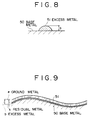
- the slide device When the truck travels at a constant speed along the grinding line (of the excess weld metal), the slide device is so controlled that the motor load current of the grinder is maintained constant, so that the metal removal rate (mm3 ⁇ min) is always kept constant even if the abrasive grinding disk is exhausted. Therefore, in case of excess metal having a cross-section as shown in Fig. 8, substantially uniformly distributed along the welding line as shown in Fig. 9, even if the base metal surface is deformed, equal finishing over such deformed surface is performed. Further since the apparatus is not affected by gravity as occurs in a system for controlling the grinding pressure, there is an advantage that the controlling capacity is stable for any grinding attitude such as facing in a horizontal direction or a vertical direction.
- (A) is automatically actuated by an external command, however an unground portion remains at the point of grinding initiation.
- (B) and (C) are utility systems where no unground portions remain, however the switch control requires monitoring by a person.
- the object of the present invention is to provide an improved automatic grinding apparatus which substantially prevents the grinding disk from coming into contact with or intruding into the object to be ground, or damaging the base metal surface when a robot is used as the travelling device for an electronic grinder.
- an automatic grinding apparatus utilizing:
- the automatic grinding apparatus of the present invention preferably further comprises means for fixing or halting a control faculty of the sliding device at an optional time during grinding so as to maintain the relative positions of the grinder and the sliding device in a selected state, and means for stopping rotation of the grinding motor and actuating the sliding device to a position where the grinder is kept apart from the object to be ground at the end of the grinding process.
- noise is preferably removed by a smoothing circuit after the load current of the electronic grinder is detected and converted to direct current by a rectifier circuit.
- the output of the smoothing circuit is compared with a set current level by a comparator and the elevation motor is actuated to elevate the grinder to approach or to be apart from the work piece respectively due to the variation of the load current, which is smaller or bigger than the set current level. Since the load current of the electronic grinder is kept constant, a certain quantity of the excess metal can be ground away so far as the travelling speed of the grinder is constant.
- the load current of the grinder it is possible to control the load current of the grinder to be kept constant by the industrial robot.
- the weight of the robot body is large and the robot has a lack of rigidity at the articulated portion thereof, the wrist portion there is necessarily late for following up thereafter.
- the sliding device is attached to the wrist portion of the robot and a light grinder is controlled in one axis of the sliding direction, so that the following capacity of the grinding disk is improved.
- the single axis sliding device is attached to the wrist portion of the robot and can follow the surface of the workpiece up to the exhaustion of the grinding disk and to the deformed surface of the base metal, the robot body need not to be controlled specifically except for moving the wrist thereof along the grinding line.
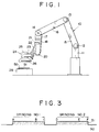
- Fig. 1 is a front view of the apparatus made in accordance with the present invention and Fig. 2 is a diagrammatic view of the control device of the apparatus.
- An articulated-type robot 10 is used for actuating an end arm 17 three-dimensionally through several joints 12, 13, 14 and arms 15, 16 provided at the upper portion of a column 11.
- a sliding device 20 is secured to the end arm 17 and a turning plate 23 providing a wrist-like structure is provided at a slider 22 for mounting a constant speed rotating grinder 24.
- the electronic grinder 24 comprises a motor 25 and a grinding stone disk 26.
- the sliding device 20 comprises an elevation motor 21 provided at the upper portion thereof and a supporting block threaded to engage the output shaft of the motor.
- the grinding disk 26 is disposed at the upper portion of excess weld metal 51 (see Fig. 8) of a workpiece 50 set on a frame 28 and is controlled by a predetermined program to grind the excess metal.
- Fig. 2 is a block diagram of a control circuit in which an alternating current reversible motor is used for the elevation motor 21.
- the control circuit includes timer means generating a signal for actuating the sliding device 20 to have the grinding disk 26 approach the grinding surface after the slip current of the grinding motor becomes stable at grinding initiation when the grinding motor 25 is actuated; a detecting means outputting the driving signal to the travelling device simultaneously with or having a time lag after detecting that the disk 26 has contacted the metal surface to be ground, due to the variation of the load current of the grinding motor 25; and means for recovering the relative location of the disk 26 and the sliding device 20 to a home position by regulating an actuating time of the elevation motor 21 before and after the grinding process.
- the grinder motor 25, the travelling motor 27 and the elevation motor 21 of the electronic grinder 24 are actuated through an overload cutout circuit 33 by a power source 30(100v alternating current, for example).
- Travelling motors 27 (motors for swinging or rotating each rotating joint (articulation) provided on a wrist, a shoulder, an elbow portion or the like of the robot) are actuated in accordance with a signal from the robot controller (not shown) and the grinding disk 26 of the electric grinder, which is attached through the sliding device 20 and the wrist, is moved towards the surface to be ground.
- the motor 25 of the electronic grinder 24 keeps its rotation frequency constant by the electronic control device (not shown). Variations in the load current of the motor 25 are detected at a current detector 34 to indicate by a load current indication scale through a rectification circuit 31 and a smoothing circuit 32 and transferred to a comparator 36.
- the comparator 36 compares said load current with the current value which is preliminarily set at a current value setting device 35, when an absolute value of the difference resulting from said comparison exceeds the value predetermined by a sensitivity adjusting circuit 39 and said comparator actuates a reciprocal changing device 37 to allow the elevation motor 21 to rotate normally or reversely according to a positive or a negative difference.
- Recovering means for returning the sliding device to the initial point or home position comprises the reciprocal changing device 37 to allow the elevation motor 21 to rotate normally or reversely according to a signal from the programmable controller (not shown) to recover to the home position, the limit switch 44 for detecting the upper limit point of the slider 22 and the timer to actuate the elevating motor 21 so as to lower the sliding device 22 from the upper limit point for a predetermined period.
- said recovering means it is possible that the location of the slider 22 in the sliding device is directly detected by a potentiometer (not shown) and the elevating motor 21 may be actuated for controlling the location of said sliding device to a certain condition.
- the weld reinforcement has the deformed surface locally at the joint of the welding bead and accordingly there is a danger that during the apparatus travel to grind the grinding line, the high speed rotating disk collides with the surface of the object and the surface is damaged. Therefore the overload breaker 33 is provided for actuation when the load current of the motor of the electronic grinder exceeds a limit value in case of emergency.
- the overload cutout circuit 33 actuates to cut off the power source 30 and rotation of each of the motor 25, the travelling motor 27 and the elevation motor 21 is stopped to preliminarily prevent burning of the grinder and damage of the grinding disk.
- Fig. 2 that is, terminals receiving each signal from the robot control device such as actuating, halting the control, recovering to the initial or home point and stopping, a load current detector 38, timers T1 to T4, relays 41 to 43 and a limit switch 44, and these elements will be described hereinafter.
- the signal actuates the relay 41 to start the rotation of the grinding motor 25 while the operation of the relay 43, delayed by the timer T1, lowers the slide using the elevation motor 21.
- the load detecting circuit 38 disregards the smoothed load current of the grinder motor 25 and from the moment of said load current exceeding a certain value, the delay in turning off the relay 42 for starting the travelling motor 27 is controlled by timer T2.
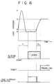
- the above starting operation is shown in Fig. 6 in respect of the load current of the grinding motor.
- the load current of the grinding motor 25 rapidly rises to P after starting and goes down to Q when the rotation of the motor reaches a nominal speed and stabilises.
- the load detecting circuit 38 starts monitoring.
- the load current rises again when the grinding disk contact the object to be ground and from the moment of the current exceeds the threshold value R, the load detecting circuit delays starting the travelling motor 27 in proportion to delay introduced by the timer T2.
- T1 is substantially constant (about 2 seconds is normal), while T2 varies due to the load set value S. That is, to prevent an unground portion remaining, T2 is set large when the value S is large and to prevent excess grinding. T2 is set to be close O when the value S is small.
- the relay 43 is turned off when a signal for halting of fixing the sliding control is input, such that the respective relative positions of the sliding device and the grinder are fixed as they are. For example, as shown in Fig. 3, when grinding toward the ridgeline C of the object, by halting or fixing the sliding control at B, before C, there is no fear of the grinding disk coming into collision with the object to be ground at the next process initiation point D due to excessive lowering of the sliding device at C, and the damage of the abrasive disk between B and C is avoided. Further, when the robot moves from C to D, since the sliding control was fixed at point B, the sliding motor can be subjected to movement and thus rotated while preventing lowering of the slide.
- the initial irregularity also remains on the finishing surface in which the excess metal still remains and an intrusion into the base metal surface occurs.
- the preliminary grinding is started from the point A after the load setting value is made small, and the slide control is fixed at the point B such that the projecting portion of the excess metal is removed first. Since the load setting level is small, the consumption of the grinding disk by said preliminary grinding is less. Then the main grinding operation is carried out, while controlling the slide, to provide the carried out, while controlling the slide, to provide the plane final finished surface.
- the reciprocal changing device 37 When the signal for returning to the home position is input from the controller, the reciprocal changing device 37 normally rotates the slide elevation motor 21 to lift the slide device and said slide device stops after reaching the upper limit switch 44, then momentarily said reciprocal changing device 37 rotates the slide elevation motor 21 reversely to lower the slide device and the slide device is stopped by the timer T3.
- the rotational speed of the motor 21 is constant, the respective relative locations of the slide device, and thus the grinder, are recovered to a constant state.
- the robot is always programmed in the condition that the grinder returns to the home position and it is possible to return the grinder to said point at the time of actuating the apparatus or after replacing the grinding disk.
- the timer T3 is so set that the upper central portion of the stroke of the slide device is the home position.
- Fig. 7 shows a time chart of an operation comprising controlling of the slide, and the halting or fixing of the control and the air migration or the air cutting for the abrasive disk in the case of grinding an object in which the base metal surface is separated into two parts as shown in Fig. 3.
- an industrial robot is used as a travelling device and the sliding device is attached on the wrist of the robot to lower the grinder to approach the object when the load current of the grinding motor is smaller than the set value, and to raise it relative to the object when the load current of the grinding motor is larger than the set value.
- This elevation is controlled in a single axis of the sliding direction by the sliding motor and the following capacity of the grinding disk is improved whilst simplifying controlling of the robot. That is, since the robot runs by detecting that the grinding is started, the predetermined grinding is possible even if the position of the object to be ground dislocates from the position which the robot has been programed to expect.
- the apparatus made in accordance with the present invention does not damage the base metal surface such as an intrusion even if the grinding process is halted at any position of the metal surface to be ground.
Landscapes
- Engineering & Computer Science (AREA)
- Robotics (AREA)
- Mechanical Engineering (AREA)
- Human Computer Interaction (AREA)
- Manufacturing & Machinery (AREA)
- Physics & Mathematics (AREA)
- General Physics & Mathematics (AREA)
- Automation & Control Theory (AREA)
- Finish Polishing, Edge Sharpening, And Grinding By Specific Grinding Devices (AREA)
- Constituent Portions Of Griding Lathes, Driving, Sensing And Control (AREA)
Claims (5)
- Appareil automatique pour abraser, contenant:une rectifieuse rotative (24) comprenant un moteur pour rectifieuse (25) et un disque de rectification (26) mis en mouvement par ledit moteur pour rectifieuse (25), moteur pour rectifieuse (25) qui ne montre pratiquement aucune variation des TPM (tours par minute) à la suite de la variation de la sollicitation s'exerçant sur ledit disque de rectification et qui reçoit un courant de charge qui est proportionnel au taux d'enlèvement de métal, caractérisé en ce que l'appareil englobe:un dispositif de déplacement sous la forme d'un robot industriel du type à articulations ou du type à coordonnées cartésiennes portant sur lui des moyens d'articulation;un dispositif de glissement attaché aux moyens d'articulation prémentionnés du robot industriel, alors que ledit dispositif de glissement (20) sur ledit robot (10) comporte un moteur de site (21). pour ajuster la distance entre ledit disque de rectification (26) et la surface de la pièce à travailler (50) devant être rectifiée, ainsi qu'une coulisse (22), actionnée par ledit moteur de site (21) et portant la rectifieuse (24) sur sa face frontale pour lever et baisser ladite rectifieuse (24), ledit dispositif de glissement (20) étant capable d'être mis en mouvement indépendamment dudit dispositif de déplacement ;un mécanisme de réglage programmable pour commander ladite rectifieuse (24) et le dispositif de glissement (20) de manière à démarrer et à arrêter le réglage de ceux-ci et de rétablir la position de repos;une minuterie (T₁) pour générer un signal destiné à actionner le dispositif de glissement (20) pour déplacer ledit disque de rectification (26) en direction de la pièce à travailler, une fois que le courant de glissement dudit moteur pour rectifieuse (25) devient stable lors du démarrage de la rectification;des moyens de détection (38) émettant un signal d'attaque audit dispositif de déplacement (27) en parallèle avec un temps de retard (T₂), ou à la suite de celui-ci, après avoir détecté que ledit disque (26) est entré en contact avec ladite surface devant être soumise à abrasion (50) en raison de la variation du courant de charge dudit moteur pour rectifieuse (25); etdes moyens (37, 44, T₃) pour rétablir l'emplacement relatif dudit disque (26) et dudit dispositif de glissement (20) par rapport à un état de repos à la suite d'une indication du mécanisme de réglage.
- Appareil automatique pour abraser, tel que revendiqué dans la revendication 1, dans lequel;
lesdits moyens de rétablissement travaillent en réglant un temps d'activité dudit moteur de site (21) à partir d'une condition limite adoptée par le disque et le dispositif de glissement à la suite d'une indication du mécanisme de réglage. - Appareil automatique pour abraser, tel que revendiqué dans la revendication 1, dans lequel;
lesdits moyens de rétablissement comportent des moyens pour asservir l'emplacement relatif dudit disque (26) ainsi que dudit dispositif de glissement (20) vers un état de repos en détectant directement, par l'intermédiaire d'un potentiomètre, la variation de la position de la coulisse par rapport à la position limite. - Appareil automatique pour abraser, tel que revendiqué dans la revendication 1 et comprenant en outre:
des moyens pour bloquer une faculté de commande du dispositif de glissement (20) à un moment choisi au cours de l'abrasion de sorte à maintenir les positions relatives de la rectifieuse (25) et du dispositif de glissement (26). - Appareil automatique pour abraser, tel que revendiqué dans la revendication 1 et comprenant en outre:
des moyens pour arrêter la rotation du moteur de la rectifieuse (25) et mettre en marche le dispositif de glissement (20) dans une direction s'écartant de la pièce à travailler devant être soumise à abrasion à la fin du processus d'abrasion.
Priority Applications (3)
| Application Number | Priority Date | Filing Date | Title |
|---|---|---|---|
| EP90314389A EP0492014B1 (fr) | 1990-12-28 | 1990-12-28 | Appareil automatique pour abraser |
| DE1990626101 DE69026101T2 (de) | 1990-12-28 | 1990-12-28 | Automatische Schleifvorrichtung |
| US07/956,932 US5299389A (en) | 1990-12-21 | 1992-10-02 | Automatic grinding apparatus |
Applications Claiming Priority (2)
| Application Number | Priority Date | Filing Date | Title |
|---|---|---|---|
| EP90314389A EP0492014B1 (fr) | 1990-12-28 | 1990-12-28 | Appareil automatique pour abraser |
| US07/956,932 US5299389A (en) | 1990-12-21 | 1992-10-02 | Automatic grinding apparatus |
Publications (2)
| Publication Number | Publication Date |
|---|---|
| EP0492014A1 EP0492014A1 (fr) | 1992-07-01 |
| EP0492014B1 true EP0492014B1 (fr) | 1996-03-20 |
Family
ID=26126969
Family Applications (1)
| Application Number | Title | Priority Date | Filing Date |
|---|---|---|---|
| EP90314389A Expired - Lifetime EP0492014B1 (fr) | 1990-12-21 | 1990-12-28 | Appareil automatique pour abraser |
Country Status (2)
| Country | Link |
|---|---|
| US (1) | US5299389A (fr) |
| EP (1) | EP0492014B1 (fr) |
Cited By (1)
| Publication number | Priority date | Publication date | Assignee | Title |
|---|---|---|---|---|
| CN108115703A (zh) * | 2017-12-29 | 2018-06-05 | 詹荃斐 | 一种新型机器人 |
Families Citing this family (38)
| Publication number | Priority date | Publication date | Assignee | Title |
|---|---|---|---|---|
| DE69116901T2 (de) * | 1990-02-27 | 1996-07-18 | Toshiba Kawasaki Kk | Robotersteuerung |
| US5441437A (en) * | 1993-02-18 | 1995-08-15 | Hulstedt; Bryan A. | Compliant constant-force follower device for surface finishing tool |
| KR0167021B1 (ko) * | 1993-03-15 | 1999-02-01 | 카타다 테쯔야 | 자동연삭장치 |
| US5565749A (en) * | 1993-04-28 | 1996-10-15 | Kabushiki Kaisha Toshiba | Method of controlling a grinder robot |
| US5816892A (en) * | 1997-02-06 | 1998-10-06 | Cobra Machine Tool Co., Inc. | Positioning control for combined milling machine and internally positioned grinding wheel |
| JPH11138426A (ja) * | 1997-11-11 | 1999-05-25 | Tokyo Electron Ltd | 研磨装置 |
| JPH11188484A (ja) * | 1997-12-25 | 1999-07-13 | Nkk Corp | 多段研削バリ取り装置 |
| CA2319041C (fr) * | 1998-01-22 | 2007-06-12 | Nitta Corporation | Meuleuse-presseuse |
| US6876899B2 (en) | 2002-01-18 | 2005-04-05 | Vulcan Engineering Co., Inc. | Method for automatic riser gate removal compensating for variance in casting |
| US20030196528A1 (en) * | 2002-04-19 | 2003-10-23 | Cooper Christopher W. | Compliant cutoff saw assembly |
| JP2005034983A (ja) * | 2003-06-26 | 2005-02-10 | Asahi Glass Co Ltd | 板状体の面取り方法 |
| US20050159840A1 (en) * | 2004-01-16 | 2005-07-21 | Wen-Jong Lin | System for surface finishing a workpiece |
| US20060016856A1 (en) * | 2004-07-21 | 2006-01-26 | Larsen Eric D | Apparatus and method for sealing a container |
| US6949005B1 (en) | 2004-07-21 | 2005-09-27 | Battelle Energy Alliance, Llc | Grinding assembly, grinding apparatus, weld joint defect repair system, and methods |
| CN102101264B (zh) * | 2009-12-21 | 2013-11-06 | 鸿富锦精密工业(深圳)有限公司 | 抛光调节机构 |
| DE102010003697B4 (de) | 2010-04-07 | 2012-12-06 | Ferrobotics Compliant Robot Technology Gmbh | Aktive Handhabungsvorrichtung und Verfahren für Kontaktaufgaben |
| DE102011006679B4 (de) | 2011-03-16 | 2018-07-12 | Ferrobotics Compliant Robot Technology Gmbh | Aktive Handhabungsvorrichtung und Verfahren für Kontaktaufgaben |
| CN103302563B (zh) * | 2012-03-14 | 2015-11-25 | 富泰华工业(深圳)有限公司 | 打磨装置及使用该打磨装置的机械手 |
| FR3018618B1 (fr) * | 2014-03-11 | 2017-09-22 | Univ Nantes | Procede et systeme de controle d'un poncage orbital |
| DE102014119532B4 (de) * | 2014-12-23 | 2016-11-03 | Ferrobotics Compliant Robot Technology Gmbh | Robotergestütztes Schleifverfahren und Vorrichtung zum robotergestützten Schleifen |
| CN109311168B (zh) | 2016-04-07 | 2022-12-13 | 菲尔罗伯蒂克斯顺从式机器人技术有限公司 | 机器人辅助的磨削装置 |
| KR101865726B1 (ko) * | 2016-05-04 | 2018-06-08 | 현대자동차 주식회사 | 루프 레이저 브레이징 시스템용 브레이징 후 공정 툴 |
| JP6457435B2 (ja) * | 2016-05-26 | 2019-01-23 | ファナック株式会社 | 研削ロボットシステム |
| FR3054154B1 (fr) * | 2016-07-21 | 2019-05-10 | Europe Technologies | Procede de martelage robotise et systeme robotise pour la mise en œuvre du procede |
| JP2018055228A (ja) * | 2016-09-27 | 2018-04-05 | 村田機械株式会社 | 管理装置及び管理方法 |
| DE202017100989U1 (de) * | 2017-02-22 | 2017-04-21 | Fibro Gmbh | Keiltrieb mit optimierter Führung |
| US10537993B2 (en) * | 2017-08-17 | 2020-01-21 | Matthew S. Ulliman | Apparatus and method for surface finishing |
| CN109879052A (zh) * | 2017-12-06 | 2019-06-14 | 沈阳新松机器人自动化股份有限公司 | 一种单放纠偏机器人及其纠偏方法 |
| US11633832B2 (en) * | 2018-11-30 | 2023-04-25 | The Boeing Company | Systems and methods for sanding a surface of a structure |
| CN109940474A (zh) * | 2019-04-10 | 2019-06-28 | 扬州洪顺电器有限公司 | 一种均压环表面打磨机器 |
| WO2020212552A1 (fr) * | 2019-04-19 | 2020-10-22 | Ferrobotics Compliant Robot Technology Gmbh | Dispositif servant au traitement assisté par robot de surfaces |
| US20220379430A1 (en) * | 2019-11-07 | 2022-12-01 | Mirka Ltd | Apparatus comprising an abrading head |
| CN111515761A (zh) * | 2020-04-20 | 2020-08-11 | 重庆长征重工有限责任公司 | 一种减少打磨误差的方法及系统 |
| CN111496679A (zh) * | 2020-04-20 | 2020-08-07 | 重庆长征重工有限责任公司 | 一种自动检测打磨余量的方法及系统 |
| CN112223293B (zh) * | 2020-10-21 | 2022-08-09 | 湖南科技大学 | 焊缝磨抛机器人在线打磨方法 |
| DE102021100314A1 (de) * | 2021-01-11 | 2022-07-14 | Aktiebolaget Skf | Bearbeitungseinheit und Verfahren zum Bearbeiten eines Bauteils |
| CN115476240A (zh) * | 2021-05-31 | 2022-12-16 | 宝山钢铁股份有限公司 | 一种直缝焊管管端焊缝打磨系统 |
| CN115647996A (zh) * | 2022-09-07 | 2023-01-31 | 罗桃英 | 一种打磨装置 |
Family Cites Families (14)
| Publication number | Priority date | Publication date | Assignee | Title |
|---|---|---|---|---|
| US3896360A (en) * | 1968-10-18 | 1975-07-22 | Siemens Ag | Method and apparatus for automatic forward feed programmed control of a machine tool |
| JPS5830110B2 (ja) * | 1974-09-03 | 1983-06-27 | セイコ−セイキ カブシキガイシヤ | ケンサクカコウセイギヨソウチ |
| CH620389A5 (fr) * | 1977-07-11 | 1980-11-28 | Fischer Ag Georg | |
| JPS57138556A (en) * | 1981-02-18 | 1982-08-26 | Brother Ind Ltd | Machine tool |
| JPS5834746A (ja) * | 1981-08-20 | 1983-03-01 | Toshiba Mach Co Ltd | ロ−ル研削盤の制御装置 |
| US4523409A (en) * | 1983-05-19 | 1985-06-18 | The Charles Stark Draper Laboratory, Inc. | Automatic contour grinding system |
| US4828451A (en) * | 1986-08-07 | 1989-05-09 | Daikin Industries, Ltd. | Industrial robot |
| JPH01121169A (ja) * | 1987-11-06 | 1989-05-12 | Aikou Eng Kk | 溶接余盛の自動研削装置 |
| EP0331265B1 (fr) * | 1988-03-01 | 1995-08-23 | Hitachi Construction Machinery Co., Ltd. | Dispositif de commande de position/force pour machine à usiner avec des degrés de liberté multiples |
| DE68918035T2 (de) * | 1988-04-08 | 1995-05-04 | Kawasaki Steel Co | Abgrat-maschine. |
| US4886529A (en) * | 1988-07-08 | 1989-12-12 | Showa Precision Machinery Co., Ltd. | Polishing robot and polishing method using the same |
| US4926309A (en) * | 1988-09-12 | 1990-05-15 | Ford Motor Company | Artificial intelligence for adaptive machining control of surface finish |
| US5067085A (en) * | 1989-05-15 | 1991-11-19 | Southwest Research Institute | Optical robotic canopy polishing system |
| US5077941A (en) * | 1990-05-15 | 1992-01-07 | Space Time Analyses, Ltd. | Automatic grinding method and system |
-
1990
- 1990-12-28 EP EP90314389A patent/EP0492014B1/fr not_active Expired - Lifetime
-
1992
- 1992-10-02 US US07/956,932 patent/US5299389A/en not_active Expired - Fee Related
Cited By (1)
| Publication number | Priority date | Publication date | Assignee | Title |
|---|---|---|---|---|
| CN108115703A (zh) * | 2017-12-29 | 2018-06-05 | 詹荃斐 | 一种新型机器人 |
Also Published As
| Publication number | Publication date |
|---|---|
| US5299389A (en) | 1994-04-05 |
| EP0492014A1 (fr) | 1992-07-01 |
Similar Documents
| Publication | Publication Date | Title |
|---|---|---|
| EP0492014B1 (fr) | Appareil automatique pour abraser | |
| KR0167021B1 (ko) | 자동연삭장치 | |
| CN110709214B (zh) | 表面处理系统的控制方法 | |
| JP3041030B2 (ja) | グラインダロボット | |
| CN104044137A (zh) | 机器人系统及机器人系统的控制方法 | |
| JP2016179510A (ja) | 物または人との接触を検知する機能を有するロボット制御装置 | |
| EP1213094A3 (fr) | Appareil de polissage ayant une fonction de verrouillage | |
| CN109927057B (zh) | 一种智能助力机械手控制系统 | |
| KR880000539B1 (ko) | 로보트 시스템 | |
| JPH0373887B2 (fr) | ||
| CN117699678A (zh) | 一种基于塔吊平衡臂配重运动的平衡控制方法 | |
| US20060202556A1 (en) | Control device for automatic machine | |
| JPH0360963A (ja) | 自動研削装置 | |
| JP2000326224A (ja) | 研削装置 | |
| JPH09155738A (ja) | ロボットの制御機構 | |
| JP2536322Y2 (ja) | 溶接余盛の自動研削装置 | |
| JPH079334A (ja) | 自動研削ロボット | |
| JPH06270059A (ja) | 研削ロボットの研削基準面位置検出装置 | |
| JP3091319B2 (ja) | 揚重装置 | |
| JP4314741B2 (ja) | ワーク搬入確認装置 | |
| KR20230093865A (ko) | 이동형 몸체 로봇 기반 부품 피니싱 시스템 및 피니싱 공정방법 | |
| JPH07115286B2 (ja) | 溶接余盛の自動研削装置 | |
| JPH0899248A (ja) | 衝突時トルク制御装置 | |
| JPH11165282A (ja) | 力制御ロボット | |
| JPH0675619A (ja) | トラバース研削機能を有する数値制御装置 |
Legal Events
| Date | Code | Title | Description |
|---|---|---|---|
| PUAI | Public reference made under article 153(3) epc to a published international application that has entered the european phase |
Free format text: ORIGINAL CODE: 0009012 |
|
| 17P | Request for examination filed |
Effective date: 19910111 |
|
| AK | Designated contracting states |
Kind code of ref document: A1 Designated state(s): DE FR GB SE |
|
| 17Q | First examination report despatched |
Effective date: 19940506 |
|
| GRAH | Despatch of communication of intention to grant a patent |
Free format text: ORIGINAL CODE: EPIDOS IGRA |
|
| GRAA | (expected) grant |
Free format text: ORIGINAL CODE: 0009210 |
|
| AK | Designated contracting states |
Kind code of ref document: B1 Designated state(s): DE FR GB SE |
|
| REF | Corresponds to: |
Ref document number: 69026101 Country of ref document: DE Date of ref document: 19960425 |
|
| ET | Fr: translation filed | ||
| PLBE | No opposition filed within time limit |
Free format text: ORIGINAL CODE: 0009261 |
|
| STAA | Information on the status of an ep patent application or granted ep patent |
Free format text: STATUS: NO OPPOSITION FILED WITHIN TIME LIMIT |
|
| 26N | No opposition filed | ||
| PGFP | Annual fee paid to national office [announced via postgrant information from national office to epo] |
Ref country code: SE Payment date: 20011206 Year of fee payment: 12 |
|
| PGFP | Annual fee paid to national office [announced via postgrant information from national office to epo] |
Ref country code: FR Payment date: 20011212 Year of fee payment: 12 |
|
| PGFP | Annual fee paid to national office [announced via postgrant information from national office to epo] |
Ref country code: GB Payment date: 20011227 Year of fee payment: 12 |
|
| REG | Reference to a national code |
Ref country code: GB Ref legal event code: IF02 |
|
| PGFP | Annual fee paid to national office [announced via postgrant information from national office to epo] |
Ref country code: DE Payment date: 20020109 Year of fee payment: 12 |
|
| PG25 | Lapsed in a contracting state [announced via postgrant information from national office to epo] |
Ref country code: GB Free format text: LAPSE BECAUSE OF NON-PAYMENT OF DUE FEES Effective date: 20021228 |
|
| PG25 | Lapsed in a contracting state [announced via postgrant information from national office to epo] |
Ref country code: SE Free format text: LAPSE BECAUSE OF NON-PAYMENT OF DUE FEES Effective date: 20021229 |
|
| PG25 | Lapsed in a contracting state [announced via postgrant information from national office to epo] |
Ref country code: DE Free format text: LAPSE BECAUSE OF NON-PAYMENT OF DUE FEES Effective date: 20030701 |
|
| EUG | Se: european patent has lapsed | ||
| GBPC | Gb: european patent ceased through non-payment of renewal fee |
Effective date: 20021228 |
|
| PG25 | Lapsed in a contracting state [announced via postgrant information from national office to epo] |
Ref country code: FR Free format text: LAPSE BECAUSE OF NON-PAYMENT OF DUE FEES Effective date: 20030901 |
|
| REG | Reference to a national code |
Ref country code: FR Ref legal event code: ST |