EP0492014A1 - Appareil automatique pour abraser - Google Patents
Appareil automatique pour abraser Download PDFInfo
- Publication number
- EP0492014A1 EP0492014A1 EP90314389A EP90314389A EP0492014A1 EP 0492014 A1 EP0492014 A1 EP 0492014A1 EP 90314389 A EP90314389 A EP 90314389A EP 90314389 A EP90314389 A EP 90314389A EP 0492014 A1 EP0492014 A1 EP 0492014A1
- Authority
- EP
- European Patent Office
- Prior art keywords
- grinding
- grinder
- motor
- sliding device
- ground
- Prior art date
- Legal status (The legal status is an assumption and is not a legal conclusion. Google has not performed a legal analysis and makes no representation as to the accuracy of the status listed.)
- Granted
Links
Images


Classifications
-
- G—PHYSICS
- G05—CONTROLLING; REGULATING
- G05B—CONTROL OR REGULATING SYSTEMS IN GENERAL; FUNCTIONAL ELEMENTS OF SUCH SYSTEMS; MONITORING OR TESTING ARRANGEMENTS FOR SUCH SYSTEMS OR ELEMENTS
- G05B19/00—Program-control systems
- G05B19/02—Program-control systems electric
- G05B19/18—Numerical control [NC], i.e. automatically operating machines, in particular machine tools, e.g. in a manufacturing environment, so as to execute positioning, movement or co-ordinated operations by means of program data in numerical form
- G05B19/416—Numerical control [NC], i.e. automatically operating machines, in particular machine tools, e.g. in a manufacturing environment, so as to execute positioning, movement or co-ordinated operations by means of program data in numerical form characterised by control of velocity, acceleration or deceleration
- G05B19/4163—Adaptive control of feed or cutting velocity
-
- B—PERFORMING OPERATIONS; TRANSPORTING
- B25—HAND TOOLS; PORTABLE POWER-DRIVEN TOOLS; MANIPULATORS
- B25J—MANIPULATORS; CHAMBERS PROVIDED WITH MANIPULATION DEVICES
- B25J11/00—Manipulators not otherwise provided for
- B25J11/005—Manipulators for mechanical processing tasks
- B25J11/0065—Polishing or grinding
-
- B—PERFORMING OPERATIONS; TRANSPORTING
- B25—HAND TOOLS; PORTABLE POWER-DRIVEN TOOLS; MANIPULATORS
- B25J—MANIPULATORS; CHAMBERS PROVIDED WITH MANIPULATION DEVICES
- B25J9/00—Program-controlled manipulators
- B25J9/16—Program controls
- B25J9/1679—Program controls characterised by the tasks executed
- B25J9/1684—Tracking a line or surface by means of sensors
-
- G—PHYSICS
- G05—CONTROLLING; REGULATING
- G05B—CONTROL OR REGULATING SYSTEMS IN GENERAL; FUNCTIONAL ELEMENTS OF SUCH SYSTEMS; MONITORING OR TESTING ARRANGEMENTS FOR SUCH SYSTEMS OR ELEMENTS
- G05B2219/00—Program-control systems
- G05B2219/30—Nc systems
- G05B2219/37—Measurements
- G05B2219/37285—Load, current taken by motor
-
- G—PHYSICS
- G05—CONTROLLING; REGULATING
- G05B—CONTROL OR REGULATING SYSTEMS IN GENERAL; FUNCTIONAL ELEMENTS OF SUCH SYSTEMS; MONITORING OR TESTING ARRANGEMENTS FOR SUCH SYSTEMS OR ELEMENTS
- G05B2219/00—Program-control systems
- G05B2219/30—Nc systems
- G05B2219/37—Measurements
- G05B2219/37405—Contact detection between workpiece and tool, probe, feeler
-
- G—PHYSICS
- G05—CONTROLLING; REGULATING
- G05B—CONTROL OR REGULATING SYSTEMS IN GENERAL; FUNCTIONAL ELEMENTS OF SUCH SYSTEMS; MONITORING OR TESTING ARRANGEMENTS FOR SUCH SYSTEMS OR ELEMENTS
- G05B2219/00—Program-control systems
- G05B2219/30—Nc systems
- G05B2219/45—Nc applications
- G05B2219/45058—Grinding, polishing robot
-
- G—PHYSICS
- G05—CONTROLLING; REGULATING
- G05B—CONTROL OR REGULATING SYSTEMS IN GENERAL; FUNCTIONAL ELEMENTS OF SUCH SYSTEMS; MONITORING OR TESTING ARRANGEMENTS FOR SUCH SYSTEMS OR ELEMENTS
- G05B2219/00—Program-control systems
- G05B2219/30—Nc systems
- G05B2219/49—Nc machine tool, till multiple
- G05B2219/49362—Tool, probe at constant height to surface during machining
-
- G—PHYSICS
- G05—CONTROLLING; REGULATING
- G05B—CONTROL OR REGULATING SYSTEMS IN GENERAL; FUNCTIONAL ELEMENTS OF SUCH SYSTEMS; MONITORING OR TESTING ARRANGEMENTS FOR SUCH SYSTEMS OR ELEMENTS
- G05B2219/00—Program-control systems
- G05B2219/30—Nc systems
- G05B2219/50—Machine tool, machine tool null till machine tool work handling
- G05B2219/50109—Soft approach, engage, retract, escape, withdraw path for tool to workpiece
-
- G—PHYSICS
- G05—CONTROLLING; REGULATING
- G05B—CONTROL OR REGULATING SYSTEMS IN GENERAL; FUNCTIONAL ELEMENTS OF SUCH SYSTEMS; MONITORING OR TESTING ARRANGEMENTS FOR SUCH SYSTEMS OR ELEMENTS
- G05B2219/00—Program-control systems
- G05B2219/30—Nc systems
- G05B2219/50—Machine tool, machine tool null till machine tool work handling
- G05B2219/50113—Short stroke, retract tool, safe distance from workpiece surface, hover height
Definitions
- This invention relates to an automatic grinding apparatus used for finishing a work piece by removing excess weld metal, deburring or chamferring.
- the apparatus comprises an electronic grinder whose motor load current decreases or increases due to the metal removal quantity per unit hour, a slider supporting the grinder, a sliding device elevating the slider, a travelling truck and rails.
- the travelling truck runs parallel to the grinding line (of the excess weld metal or weld reinforcement) on the rails at a constant speed.
- a pinion projects from the bottom of the travelling truck to engage a rack provided on the guide rails.
- a travelling motor which is contained in the travelling device, rotates the pinion through a speed reduction device to move the truck along the longitudinal direction of the rails at a constant speed.
- the sliding device controls the perpendicular distance between the electronic grinder and the excess metal welding.
- a supporting block contained in the slider is threaded to engage an output shaft of the slide elevation motor which is provided at the upper end of the device to elevate the slider by rotation of the elevation motor.
- the electronic grinder is attached by a holder provided at the front portion of the slider.
- the slide device When the truck travels at a constant speed along the grinding line (of the excess weld metal), the slide device is so controlled that the motor load current of the grinder is maintained constant, so that the metal removal rate (mm3 /min) is always kept constant even if the abrasive grinding disk is exhausted. Therefore, in case of excess metal having a cross-section as shown in Fig.8, substantially uniformly distributed along the welding line as shown in Fig. 9, even if the base metal surface is deformed, equal finishing over such deformed surface is performed. Further since the apparatus is not effected by gravity as occurs in a system for controlling the grinding pressure, there is an advantage that the controlling capacity is stable for any grinding attitude such as facing in a horizontal direction or a vertical direction.
- (A) is automatically actuated by an external command, however an unground portion remains near around the grinding initiation.
- (B) and (C) are utility systems where no unground portions remain, however the switch control requires monitoring by a person.
- the object of the present invention is to provide an improved automatic grinding apparatus which substantially prevents the abrasive disk from coming into contact with or intruding into the object to be ground, or damaging the base metal surface when a robot is used as the travelling device for an electronic grinder.
- a travelling device for an electronic grinder is supported by an articulated type or a cartesian coordinate type industrial robot.
- An automatic grinding apparatus of the present invention comprises an electronic grinder containing a motor whose load current increases or decreases due to the metal removal quantity per unit time, a travelling device moving said grinder three-dimensionally over the grinding surface, a sliding device adjusting the distance between said grinder and the object to be ground, and a control device controlling said sliding device to keep the load current of the grinding motor constant.
- Said control device includes sequence controlling means to first actuate the grinding motor in a condition of halting the travelling device at the grinding initiation, to permit said grinder to approach the object to be ground after a certain time, and to start the travelling device simultaneously or a little later after detecting that an abrasive disk mounted on the grinder has contacted the object to be ground due to the variation of the load current of the grinding motor, and said control device further includes means to recover respective relative positions of the grinder and the sliding device to a certain condition by regulating the operation time of an elevation motor for the sliding device or by directly detecting a location of the slider of the sliding device before and after a grinding process.
- the automatic grinding apparatus of the present invention preferably further comprises means for halting a control faculty of the sliding device at an optional time during grinding so as to keep the relative positions of the grinder and the sliding device in a state at that time, and means for stopping rotation of the grinding motor thus actuating the sliding device to a position where the grinder is kept apart from the object to be ground at the grinding end process.
- noise is preferably removed by a smoothing circuit after the load current of the electronic grinder is detected and converted to direct current by a rectifier circuit.
- the above output is compared with a setting current level by a comparator to actuate the elevation motor which lowers or raises the grinder at a time when the substantial load current is smaller or bigger than the set current level, respectively. Since the load current of the electronic grinder is kept constant, a certain quantity of the excess metal can be ground away so far as the travelling speed of the grinder is constant.
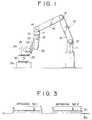
- Fig. 1 is a front view of the appratus made in accordance with the present invention and Fig. 2 is a diagram view of the controll device of the appratus.
- An articulated type robot 10 is used for actuating an end arm 17 a three-dimentionally through several of joints 12, 13,14 and arms 15, 16 provided at the upper portion of a column 11.
- a sliding device 20 is secured to the end arm 17 and a turning plate provided at a slider 22 for attaching an electronic grinder 24.
- the electronic grinder 24 comprises a motor 25 and a grinding stone disk 26.
- the sliding device 20 contains the elevation motor provided at the upper portion thereof and the supporting block threaded to engage the output shaft of the motor.
- the abrasive disk disk 26 is disposed at the direct upper portion of a welded excess metal 51 of a work 50 set on a frame 28 and is approached by a predetermined program to grind the excess metal.
- Fig. 2 is a block diagram of a control circuit in case of an alternating current reversible motor being used for the elevation motor 25 .
- All of the motor 25 the traveling motor 27 and the elevation motor 21 of the electronic grinder 24 is actuated through an overload cutout circuit 38 by a power source 30(100v alternating current, for example).
- a plurality of travelling motors 27 rotate to allow a seam speed of the grinder travelling a three-dimentinally to be optionally constant by a control device( not shown) for the robot.
- the motor 25 of the electronic grinder 24 is kept it's rotation frequency by the electronic control device (not shown).
- variable load current of the motor 25 is detected at an current detector 34 to indicate in a load current indication scale through a rectification circuit 31 and a smoothing circuit 32 and transferred to a comparator 36.
- the comparator 36 compares said load current with the current value which is preliminary set in a current value setting device 35, when an absolute value of the difference resulting from said comparison exceeds the value predetermined by a sensitivity adjusting circuit 39 and said comparator actuates a reciprocal changing device 37 to allow the motor 21 for elevating to rotate normally or reversely according to a positive or a negative difference .
- the overload cutout circuit 33 actuates to cut the power source 30 and each rotation of the motor 25 , the travelling motor 27 and the elevation motor 21 of the grinder 24 is stopped to preliminaly prevent the burning of the grinder and the damage of the abrasive disk.
- Fig. 2 that is, terminals receiving each signal from the robot control device such as actuating, halting the control , recovering to the initial point and stopping, a load current detector 38, timers T1 to T 4 , relays 41 to 43 and a limit switch 44 and will be described hereinafter.
- the signal actuates the relay 41 to start the rotation of the grinding motor 25 and the relay 43 is late to be operated in proportion to the timer T 1 to fall the slide by the elevation motor 21 for elevating the slide.
- the load detecting circuit 38 disregards the smoothed load current of the grinder motor 25 and from the moment of said load current exceeding a certain value, the relay 42 is late to be turned off in proportion to the timer T 2 to start the travelling motor 27 .
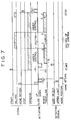
- Fig. 6 Above starting opertion is shown in Fig. 6 in respect of the load current of the grinding motor.
- the load current of the grinding motor 25 rapidly rises to P after the starting and goes clown to Q when the rotation of the motor becomes a nominal speed to be stabilated.
- the load detecting circuit 38 starts the monitoring. Since the load current rises again when the abrasive disk contacts the object to be ground, from the moment of the current exceeding the threshold value R, the load detecting circuit is late to start the travelling motor 27 in proportion to the timer T2 .
- T 1 is substantially constant( about 2 seconds in normal)
- T 2 varies due to the load set value S. That is , to prevent the unground portion to remain, T2 is set large when the value S is large and to prevent the excess grinding, T 2 is set to be close O when the value S is small.
- the sliding device will entirely fall down to the lower limit in moving. Simultaneously when the robot reaches at the D point, the signal for halting the control is released and the relay 43 is operated, the grinding process can start soon by recovering the faculty of controlling the slide.
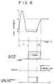
- the irregularity on the surface of the object is ground by halting or recovering the faculty of controlling the slide.
- the irregularity in case of grinding the irregular excess metal by controlling the slide, the irregularity also remains on the finishing surface in which the excess metal still remains and an intrusion into the base metal surface occurs.
- the preliminal grinding is started from the point A after the load setting value is made small, the slide control is halted at the point B where the slide controlling facilitates , then the projecting portion of the excess metal is removed first. Since the load setting level is small, the consumption of the abrasive disk by said preliminal grinding is less. Then the main grinding by controlling the slide is continued to perform the plane final finished surface.
- the reciprocal changing device 37 normally rotates the slide elevation motor 21 to rise the slide device and said slide device stops after reaching to the upper limit switch 44 , then momentaly said reciprocal changing device 37 rotates the slide elevation motor 21 reversely to fall down the slide device and the slide device stops by the timer T 3 .
- the rotation speed of the motor 21 in respect of the timer T3 is set constant, by above described operation, respective relative locations of the slide device and the grinder are surely recovered to a constant state.
- the robot is always programmed in the condition that the grinder recovers to the home position and it is possible to return the grinder to said point at the time of actuating the apparatus or after exchanging the abrasive disk .
- the timer T 3 is so set that the rather upper central portion of stroke of the slide device is to be the home position.
- the location of the slider 22 of the sliding device is directly detected by a potentiometer and is rendered to be constant by actuating the elevation motor .
- the relays 41 and 42 are cut to stop both of the travelling motor 27 and the grinding motor 25, simultaneously the slide device is risen by rotating the motor 21 normally for elevating the slide and the slide is stopped by a timer T 4 .
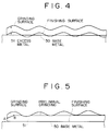
- Fig. 7 shows a time chart of the operation comprising the recovering to the home position , the starting, the controlling, and the halting of the control (the air immigration or the air cutting for the abrasive disk) in case of grinding the object of which base metal surface is separated into two parts as shown in Fig. 3..
- the apparatus made in accordance with the present invention has an effect not to damage the base metal surface such as an intrusion even if the grinding process is halted at any position of the metal surface to be ground.
Landscapes
- Engineering & Computer Science (AREA)
- Robotics (AREA)
- Mechanical Engineering (AREA)
- Human Computer Interaction (AREA)
- Manufacturing & Machinery (AREA)
- Physics & Mathematics (AREA)
- General Physics & Mathematics (AREA)
- Automation & Control Theory (AREA)
- Finish Polishing, Edge Sharpening, And Grinding By Specific Grinding Devices (AREA)
- Constituent Portions Of Griding Lathes, Driving, Sensing And Control (AREA)
Priority Applications (3)
| Application Number | Priority Date | Filing Date | Title |
|---|---|---|---|
| EP90314389A EP0492014B1 (fr) | 1990-12-28 | 1990-12-28 | Appareil automatique pour abraser |
| DE1990626101 DE69026101T2 (de) | 1990-12-28 | 1990-12-28 | Automatische Schleifvorrichtung |
| US07/956,932 US5299389A (en) | 1990-12-21 | 1992-10-02 | Automatic grinding apparatus |
Applications Claiming Priority (2)
| Application Number | Priority Date | Filing Date | Title |
|---|---|---|---|
| EP90314389A EP0492014B1 (fr) | 1990-12-28 | 1990-12-28 | Appareil automatique pour abraser |
| US07/956,932 US5299389A (en) | 1990-12-21 | 1992-10-02 | Automatic grinding apparatus |
Publications (2)
| Publication Number | Publication Date |
|---|---|
| EP0492014A1 true EP0492014A1 (fr) | 1992-07-01 |
| EP0492014B1 EP0492014B1 (fr) | 1996-03-20 |
Family
ID=26126969
Family Applications (1)
| Application Number | Title | Priority Date | Filing Date |
|---|---|---|---|
| EP90314389A Expired - Lifetime EP0492014B1 (fr) | 1990-12-21 | 1990-12-28 | Appareil automatique pour abraser |
Country Status (2)
| Country | Link |
|---|---|
| US (1) | US5299389A (fr) |
| EP (1) | EP0492014B1 (fr) |
Cited By (3)
| Publication number | Priority date | Publication date | Assignee | Title |
|---|---|---|---|---|
| EP0627283A1 (fr) * | 1993-04-28 | 1994-12-07 | Kabushiki Kaisha Toshiba | Méthode de commande d'un robot de meulage |
| CN112223293A (zh) * | 2020-10-21 | 2021-01-15 | 湖南科技大学 | 焊缝磨抛机器人在线打磨方法 |
| CN115476240A (zh) * | 2021-05-31 | 2022-12-16 | 宝山钢铁股份有限公司 | 一种直缝焊管管端焊缝打磨系统 |
Families Citing this family (36)
| Publication number | Priority date | Publication date | Assignee | Title |
|---|---|---|---|---|
| DE69116901T2 (de) * | 1990-02-27 | 1996-07-18 | Toshiba Kawasaki Kk | Robotersteuerung |
| US5441437A (en) * | 1993-02-18 | 1995-08-15 | Hulstedt; Bryan A. | Compliant constant-force follower device for surface finishing tool |
| KR0167021B1 (ko) * | 1993-03-15 | 1999-02-01 | 카타다 테쯔야 | 자동연삭장치 |
| US5816892A (en) * | 1997-02-06 | 1998-10-06 | Cobra Machine Tool Co., Inc. | Positioning control for combined milling machine and internally positioned grinding wheel |
| JPH11138426A (ja) * | 1997-11-11 | 1999-05-25 | Tokyo Electron Ltd | 研磨装置 |
| JPH11188484A (ja) * | 1997-12-25 | 1999-07-13 | Nkk Corp | 多段研削バリ取り装置 |
| CA2319041C (fr) * | 1998-01-22 | 2007-06-12 | Nitta Corporation | Meuleuse-presseuse |
| US6876899B2 (en) | 2002-01-18 | 2005-04-05 | Vulcan Engineering Co., Inc. | Method for automatic riser gate removal compensating for variance in casting |
| US20030196528A1 (en) * | 2002-04-19 | 2003-10-23 | Cooper Christopher W. | Compliant cutoff saw assembly |
| JP2005034983A (ja) * | 2003-06-26 | 2005-02-10 | Asahi Glass Co Ltd | 板状体の面取り方法 |
| US20050159840A1 (en) * | 2004-01-16 | 2005-07-21 | Wen-Jong Lin | System for surface finishing a workpiece |
| US20060016856A1 (en) * | 2004-07-21 | 2006-01-26 | Larsen Eric D | Apparatus and method for sealing a container |
| US6949005B1 (en) | 2004-07-21 | 2005-09-27 | Battelle Energy Alliance, Llc | Grinding assembly, grinding apparatus, weld joint defect repair system, and methods |
| CN102101264B (zh) * | 2009-12-21 | 2013-11-06 | 鸿富锦精密工业(深圳)有限公司 | 抛光调节机构 |
| DE102010003697B4 (de) | 2010-04-07 | 2012-12-06 | Ferrobotics Compliant Robot Technology Gmbh | Aktive Handhabungsvorrichtung und Verfahren für Kontaktaufgaben |
| DE102011006679B4 (de) | 2011-03-16 | 2018-07-12 | Ferrobotics Compliant Robot Technology Gmbh | Aktive Handhabungsvorrichtung und Verfahren für Kontaktaufgaben |
| CN103302563B (zh) * | 2012-03-14 | 2015-11-25 | 富泰华工业(深圳)有限公司 | 打磨装置及使用该打磨装置的机械手 |
| FR3018618B1 (fr) * | 2014-03-11 | 2017-09-22 | Univ Nantes | Procede et systeme de controle d'un poncage orbital |
| DE102014119532B4 (de) * | 2014-12-23 | 2016-11-03 | Ferrobotics Compliant Robot Technology Gmbh | Robotergestütztes Schleifverfahren und Vorrichtung zum robotergestützten Schleifen |
| CN109311168B (zh) | 2016-04-07 | 2022-12-13 | 菲尔罗伯蒂克斯顺从式机器人技术有限公司 | 机器人辅助的磨削装置 |
| KR101865726B1 (ko) * | 2016-05-04 | 2018-06-08 | 현대자동차 주식회사 | 루프 레이저 브레이징 시스템용 브레이징 후 공정 툴 |
| JP6457435B2 (ja) * | 2016-05-26 | 2019-01-23 | ファナック株式会社 | 研削ロボットシステム |
| FR3054154B1 (fr) * | 2016-07-21 | 2019-05-10 | Europe Technologies | Procede de martelage robotise et systeme robotise pour la mise en œuvre du procede |
| JP2018055228A (ja) * | 2016-09-27 | 2018-04-05 | 村田機械株式会社 | 管理装置及び管理方法 |
| DE202017100989U1 (de) * | 2017-02-22 | 2017-04-21 | Fibro Gmbh | Keiltrieb mit optimierter Führung |
| US10537993B2 (en) * | 2017-08-17 | 2020-01-21 | Matthew S. Ulliman | Apparatus and method for surface finishing |
| CN109879052A (zh) * | 2017-12-06 | 2019-06-14 | 沈阳新松机器人自动化股份有限公司 | 一种单放纠偏机器人及其纠偏方法 |
| CN108115703A (zh) * | 2017-12-29 | 2018-06-05 | 詹荃斐 | 一种新型机器人 |
| US11633832B2 (en) * | 2018-11-30 | 2023-04-25 | The Boeing Company | Systems and methods for sanding a surface of a structure |
| CN109940474A (zh) * | 2019-04-10 | 2019-06-28 | 扬州洪顺电器有限公司 | 一种均压环表面打磨机器 |
| WO2020212552A1 (fr) * | 2019-04-19 | 2020-10-22 | Ferrobotics Compliant Robot Technology Gmbh | Dispositif servant au traitement assisté par robot de surfaces |
| US20220379430A1 (en) * | 2019-11-07 | 2022-12-01 | Mirka Ltd | Apparatus comprising an abrading head |
| CN111515761A (zh) * | 2020-04-20 | 2020-08-11 | 重庆长征重工有限责任公司 | 一种减少打磨误差的方法及系统 |
| CN111496679A (zh) * | 2020-04-20 | 2020-08-07 | 重庆长征重工有限责任公司 | 一种自动检测打磨余量的方法及系统 |
| DE102021100314A1 (de) * | 2021-01-11 | 2022-07-14 | Aktiebolaget Skf | Bearbeitungseinheit und Verfahren zum Bearbeiten eines Bauteils |
| CN115647996A (zh) * | 2022-09-07 | 2023-01-31 | 罗桃英 | 一种打磨装置 |
Citations (5)
| Publication number | Priority date | Publication date | Assignee | Title |
|---|---|---|---|---|
| US3896360A (en) * | 1968-10-18 | 1975-07-22 | Siemens Ag | Method and apparatus for automatic forward feed programmed control of a machine tool |
| US4451187A (en) * | 1981-02-18 | 1984-05-29 | Brother Kogyo Kabushiki Kaisha | Machine tool |
| US4516212A (en) * | 1981-08-20 | 1985-05-07 | Toshiba Kikai Kabushiki Kaisha | Control system for roll grinding machine |
| EP0331265A2 (fr) * | 1988-03-01 | 1989-09-06 | Hitachi Construction Machinery Co., Ltd. | Dispositif de commande de position/force pour machine à usiner avec des degrés de liberté multiples |
| EP0359378A2 (fr) * | 1988-09-12 | 1990-03-21 | Ford Motor Company Limited | Intelligence artificielle pour la commande d'usinage de finition de surface adaptatif |
Family Cites Families (9)
| Publication number | Priority date | Publication date | Assignee | Title |
|---|---|---|---|---|
| JPS5830110B2 (ja) * | 1974-09-03 | 1983-06-27 | セイコ−セイキ カブシキガイシヤ | ケンサクカコウセイギヨソウチ |
| CH620389A5 (fr) * | 1977-07-11 | 1980-11-28 | Fischer Ag Georg | |
| US4523409A (en) * | 1983-05-19 | 1985-06-18 | The Charles Stark Draper Laboratory, Inc. | Automatic contour grinding system |
| US4828451A (en) * | 1986-08-07 | 1989-05-09 | Daikin Industries, Ltd. | Industrial robot |
| JPH01121169A (ja) * | 1987-11-06 | 1989-05-12 | Aikou Eng Kk | 溶接余盛の自動研削装置 |
| DE68918035T2 (de) * | 1988-04-08 | 1995-05-04 | Kawasaki Steel Co | Abgrat-maschine. |
| US4886529A (en) * | 1988-07-08 | 1989-12-12 | Showa Precision Machinery Co., Ltd. | Polishing robot and polishing method using the same |
| US5067085A (en) * | 1989-05-15 | 1991-11-19 | Southwest Research Institute | Optical robotic canopy polishing system |
| US5077941A (en) * | 1990-05-15 | 1992-01-07 | Space Time Analyses, Ltd. | Automatic grinding method and system |
-
1990
- 1990-12-28 EP EP90314389A patent/EP0492014B1/fr not_active Expired - Lifetime
-
1992
- 1992-10-02 US US07/956,932 patent/US5299389A/en not_active Expired - Fee Related
Patent Citations (5)
| Publication number | Priority date | Publication date | Assignee | Title |
|---|---|---|---|---|
| US3896360A (en) * | 1968-10-18 | 1975-07-22 | Siemens Ag | Method and apparatus for automatic forward feed programmed control of a machine tool |
| US4451187A (en) * | 1981-02-18 | 1984-05-29 | Brother Kogyo Kabushiki Kaisha | Machine tool |
| US4516212A (en) * | 1981-08-20 | 1985-05-07 | Toshiba Kikai Kabushiki Kaisha | Control system for roll grinding machine |
| EP0331265A2 (fr) * | 1988-03-01 | 1989-09-06 | Hitachi Construction Machinery Co., Ltd. | Dispositif de commande de position/force pour machine à usiner avec des degrés de liberté multiples |
| EP0359378A2 (fr) * | 1988-09-12 | 1990-03-21 | Ford Motor Company Limited | Intelligence artificielle pour la commande d'usinage de finition de surface adaptatif |
Cited By (3)
| Publication number | Priority date | Publication date | Assignee | Title |
|---|---|---|---|---|
| EP0627283A1 (fr) * | 1993-04-28 | 1994-12-07 | Kabushiki Kaisha Toshiba | Méthode de commande d'un robot de meulage |
| CN112223293A (zh) * | 2020-10-21 | 2021-01-15 | 湖南科技大学 | 焊缝磨抛机器人在线打磨方法 |
| CN115476240A (zh) * | 2021-05-31 | 2022-12-16 | 宝山钢铁股份有限公司 | 一种直缝焊管管端焊缝打磨系统 |
Also Published As
| Publication number | Publication date |
|---|---|
| US5299389A (en) | 1994-04-05 |
| EP0492014B1 (fr) | 1996-03-20 |
Similar Documents
| Publication | Publication Date | Title |
|---|---|---|
| EP0492014A1 (fr) | Appareil automatique pour abraser | |
| US4502125A (en) | Numerical controller for an angular slide grinding machine | |
| US4423569A (en) | Automatic lens edger | |
| JP2000326224A (ja) | 研削装置 | |
| JPH0822501B2 (ja) | 自動研削装置 | |
| JPH06297366A (ja) | 産業用ロボット | |
| JP2536322Y2 (ja) | 溶接余盛の自動研削装置 | |
| JPH08112754A (ja) | 自動研削装置における研削基準面検出装置 | |
| JPH079334A (ja) | 自動研削ロボット | |
| JPH0675619A (ja) | トラバース研削機能を有する数値制御装置 | |
| JPH07115286B2 (ja) | 溶接余盛の自動研削装置 | |
| JPH06270059A (ja) | 研削ロボットの研削基準面位置検出装置 | |
| CN113985811A (zh) | 一种数控机床防碰撞控制方法及数控机床 | |
| JPH04141363A (ja) | 研削盤の研削送り開始位置修正方法および同装置 | |
| JP2504791Y2 (ja) | 研削盤における送り速度制御装置 | |
| JPH06270060A (ja) | 研削ロボットの研削基準面位置検出装置 | |
| JP2570445B2 (ja) | Nc切削装置 | |
| JP2595237Y2 (ja) | 研磨装置 | |
| JPH01205947A (ja) | ジョグ送りの一旦停止方法 | |
| JPH01121169A (ja) | 溶接余盛の自動研削装置 | |
| JPH0192052A (ja) | 加工装置の工具摩耗補正装置 | |
| SU1516264A1 (ru) | Способ электроабразивного шлифовани | |
| JPH117313A (ja) | 数値制御装置 | |
| JPH06270061A (ja) | 研削ロボットの研削基準面位置検出装置 | |
| JPH0899248A (ja) | 衝突時トルク制御装置 |
Legal Events
| Date | Code | Title | Description |
|---|---|---|---|
| PUAI | Public reference made under article 153(3) epc to a published international application that has entered the european phase |
Free format text: ORIGINAL CODE: 0009012 |
|
| 17P | Request for examination filed |
Effective date: 19910111 |
|
| AK | Designated contracting states |
Kind code of ref document: A1 Designated state(s): DE FR GB SE |
|
| 17Q | First examination report despatched |
Effective date: 19940506 |
|
| GRAH | Despatch of communication of intention to grant a patent |
Free format text: ORIGINAL CODE: EPIDOS IGRA |
|
| GRAA | (expected) grant |
Free format text: ORIGINAL CODE: 0009210 |
|
| AK | Designated contracting states |
Kind code of ref document: B1 Designated state(s): DE FR GB SE |
|
| REF | Corresponds to: |
Ref document number: 69026101 Country of ref document: DE Date of ref document: 19960425 |
|
| ET | Fr: translation filed | ||
| PLBE | No opposition filed within time limit |
Free format text: ORIGINAL CODE: 0009261 |
|
| STAA | Information on the status of an ep patent application or granted ep patent |
Free format text: STATUS: NO OPPOSITION FILED WITHIN TIME LIMIT |
|
| 26N | No opposition filed | ||
| PGFP | Annual fee paid to national office [announced via postgrant information from national office to epo] |
Ref country code: SE Payment date: 20011206 Year of fee payment: 12 |
|
| PGFP | Annual fee paid to national office [announced via postgrant information from national office to epo] |
Ref country code: FR Payment date: 20011212 Year of fee payment: 12 |
|
| PGFP | Annual fee paid to national office [announced via postgrant information from national office to epo] |
Ref country code: GB Payment date: 20011227 Year of fee payment: 12 |
|
| REG | Reference to a national code |
Ref country code: GB Ref legal event code: IF02 |
|
| PGFP | Annual fee paid to national office [announced via postgrant information from national office to epo] |
Ref country code: DE Payment date: 20020109 Year of fee payment: 12 |
|
| PG25 | Lapsed in a contracting state [announced via postgrant information from national office to epo] |
Ref country code: GB Free format text: LAPSE BECAUSE OF NON-PAYMENT OF DUE FEES Effective date: 20021228 |
|
| PG25 | Lapsed in a contracting state [announced via postgrant information from national office to epo] |
Ref country code: SE Free format text: LAPSE BECAUSE OF NON-PAYMENT OF DUE FEES Effective date: 20021229 |
|
| PG25 | Lapsed in a contracting state [announced via postgrant information from national office to epo] |
Ref country code: DE Free format text: LAPSE BECAUSE OF NON-PAYMENT OF DUE FEES Effective date: 20030701 |
|
| EUG | Se: european patent has lapsed | ||
| GBPC | Gb: european patent ceased through non-payment of renewal fee |
Effective date: 20021228 |
|
| PG25 | Lapsed in a contracting state [announced via postgrant information from national office to epo] |
Ref country code: FR Free format text: LAPSE BECAUSE OF NON-PAYMENT OF DUE FEES Effective date: 20030901 |
|
| REG | Reference to a national code |
Ref country code: FR Ref legal event code: ST |