EP0492702A1 - Korrelationsvorrichtung - Google Patents
Korrelationsvorrichtung Download PDFInfo
- Publication number
- EP0492702A1 EP0492702A1 EP91203285A EP91203285A EP0492702A1 EP 0492702 A1 EP0492702 A1 EP 0492702A1 EP 91203285 A EP91203285 A EP 91203285A EP 91203285 A EP91203285 A EP 91203285A EP 0492702 A1 EP0492702 A1 EP 0492702A1
- Authority
- EP
- European Patent Office
- Prior art keywords
- pixels
- current block
- blocks
- correlation
- window
- Prior art date
- Legal status (The legal status is an assumption and is not a legal conclusion. Google has not performed a legal analysis and makes no representation as to the accuracy of the status listed.)
- Granted
Links
Images


Classifications
-
- H—ELECTRICITY
- H04—ELECTRIC COMMUNICATION TECHNIQUE
- H04N—PICTORIAL COMMUNICATION, e.g. TELEVISION
- H04N19/00—Methods or arrangements for coding, decoding, compressing or decompressing digital video signals
- H04N19/50—Methods or arrangements for coding, decoding, compressing or decompressing digital video signals using predictive coding
- H04N19/503—Methods or arrangements for coding, decoding, compressing or decompressing digital video signals using predictive coding involving temporal prediction
- H04N19/51—Motion estimation or motion compensation
-
- G—PHYSICS
- G06—COMPUTING OR CALCULATING; COUNTING
- G06T—IMAGE DATA PROCESSING OR GENERATION, IN GENERAL
- G06T7/00—Image analysis
- G06T7/20—Analysis of motion
- G06T7/223—Analysis of motion using block-matching
-
- G—PHYSICS
- G06—COMPUTING OR CALCULATING; COUNTING
- G06T—IMAGE DATA PROCESSING OR GENERATION, IN GENERAL
- G06T2207/00—Indexing scheme for image analysis or image enhancement
- G06T2207/10—Image acquisition modality
- G06T2207/10016—Video; Image sequence
Definitions
- the regular configuration of input signals can be one-dimensional or two-dimensional. This can for example be a one-dimensional configuration where correlations can take place on blocks of input signals of acoustic origin for sound processing. A symbol of the configuration is then a value coded in binary form. Preferably, these may be two-dimensional configurations where the correlations operate on images, for example animated images, on which vectors of displacement of the animated sequence are determined between successive images. A symbol of the configuration is then a pixel.
- These applications are often undertaken to reduce data throughput. They are encountered, for example, in the field of television (high bit rate) or in the field of videophone and video conference (low bit rate).
- block to block correspondence For the estimation of movement of animated images, the technique which seems the most interesting is that called “block to block correspondence” called “block matching” in English. It consists of cutting the image into blocks of pixels. For a given block of the image, the block closest to it is determined in an earlier image in order to determine the movement of the animated sequence represented in the image. It is this movement information which is transmitted, for each block, to the receiving member placed at the end of the transmission channel.
- the principle of the processing consists in following the evolution of the content of images on successive images. This technique takes advantage of the fact that the information content varies little from one image to another. The movement of the information contained in a block is generally limited to a few neighboring blocks. This monitoring is carried out by identifying certain parts which may be the most significant or which are chosen voluntarily. This can concern all the blocks of the image.
- a reference current block (expression simplified below in "current block”) may be located differently in either anterior or posterior images. It is this displacement that must be determined. However, this movement remains limited and for this a window is defined inside which said current block is likely to be located.
- the estimated movement is the translation between the position in the image of the current block and the position in the anterior / posterior image of the anterior / posterior block which has the highest correlation. This makes it possible to determine a displacement vector relative to the current block.
- the correlation will therefore be determined pixel by pixel of the same position for all the possible positions of the current block inside the corresponding window. The same operations are repeated for the other current blocks chosen. Correlation is generally evaluated by summing for the whole block, the absolute values of the differences in characteristics from pixel to pixel block to block.
- the characteristic of the pixel is generally its luminance.
- Inter-image differential coding which is a privileged application of motion estimation, consists in transmitting a prediction error, the latter being in the present case the block of the previous image chosen in the window.
- a prediction error When the motion estimation is done correctly the prediction error is low and therefore the length of the code transmitted by a transmission channel is reduced. It is therefore understandable that the degradation of the precision of the motion estimation has an impact on the efficiency of the coding.
- the rate of prediction errors can increase by 50%. This requires an increase in throughput to achieve acceptable image quality.
- the problem is therefore to design a correlation device which allows a simplified hardware implementation (compared to a usual implementation) and which can operate in real time with a reduced prediction error rate even for image processing applications. of TV.
- the information content of the current block is ignored, and the selected reference pixels are distributed randomly in the current block.
- the selection consists in taking in reference pixels (respectively values coded in binary) having a certain position in the current block.
- These pixels which have a determined position in the current block correspond to other pixels which have the same position in blocks of the window to be analyzed.
- the correlation which is calculated between two blocks in fact takes place between the pixels of the two blocks which have the same position.
- the operation is continued for all possible positions of the current block in the window.
- the treatment is then continued with another current block associated with another search window. It is possible that the same random selection is used for several current blocks to select the position of the reference symbol (s) randomly selected.
- the position of the reference symbols in the current block is determined from a distortion function calculated for each symbol of the current block with respect to vis the surrounding symbols, the selected reference symbol (s) being chosen from the symbols whose values of the distortion function differ most from those relating to the surrounding symbols.
- This distortion function can, for example, take account of the variation of a characteristic such as luminance or the like between neighboring pixels of the same current block.
- the distortion function can be determined by calculating a Laplacian relating to the characteristic chosen for the input signal. More generally, it is possible to take into account neighboring pixels which surround a given pixel isotropically. But so that in a current block the reference pixels are not concentrated in a too localized part of the current block, it is possible to impose a distribution constraint by subdividing the current block in several zones for example in the form of a grid regular or not or any other form of mesh. In this case, it is required that all the zones or at least a part are represented by at least one pixel.
- This pixel by zone can be chosen with the same strategies as those already described for a current block.
- the selection means operate in isolation on each zone, the correlation always taking place on all the pixels of reference of the current block.
- each zone of a current block has the same number of reference pixels.
- the reference pixel (s) of the zones is (are) selected from the determination of a distortion function, preferably the reference pixel (s) is (are) selected ) in each zone so that the values of the distortion function which characterize it (them), are alternately maximum and minimum for contiguous zones.
- only a limited number of reference symbols are kept in a current block to operate the correlation calculation.
- This limited number can be chosen in several ways. It can be fixed a priori after preliminary tests which make it possible to establish a correlation calculation with an acceptable error rate. This can be done when the current block contains a reduced number of pixels, for example 4 x 4.
- this limited number can be chosen from limits imposed on the values which this distortion function can have.
- the limited number of reference symbols is therefore made to depend on the content of the image.
- this limited number remains mainly linked to the type of images, that is to say to the application itself.
- it is possible to more finely enslave said number limited to the content of the image by determining it regularly and adaptively on batches of images.
- This can be obtained using a correlation device which includes a neural network which implements the so-called "principal component analysis” method and which selects the number of the highest variances. Cyclically this number of variances is introduced into the selection means to constitute said limited number in order to operate as has already been described.
- a neural network is a known signal processing device which can, after a programming step or a learning step, carry out specific processing operations, for example a "principal component analysis" of the distribution of input signals.
- Such a neural network can for example be that described in the document: "Optimal unsupervised Learning in single-layer linear Feedforward Neural networks” T.D. SANGER Neural Networks, vol.2, 1989, p.459-473.
- the fact of making the correlation calculation relate only to certain reference symbols having a certain position in the current block makes it possible to simplify the hardware realization, to increase the processing speed while retaining the rate errors at low and controllable values.
- the correlator comprises substantially as many processors as there are possible displacements in the window and it operates on a reduced number of reference pixels which increases its execution speed relative to to use all the pixels of the current block.
- a particularly interesting case is that where each zone contains only 4 pixels, with a single reference pixel selected per zone.
- the correlator operates on a two-dimensional window of pixels with current blocks subdivided into zones containing 4 pixels each with a single reference pixel selected by zone, a two-dimensional matrix of registers storing, at a given instant, the pixels of said window.
- registers being assigned to the processing of an area, rows of said registers communicating with each other, in the two directions of the matrix, even order pixels of the window and other rows of registers communicating between them odd order pixels of the window, this communication being unidirectional in one direction of the window and being bidirectional in the other direction of the window, a processor being assigned to the processing of each displacement vector and operating with four registers containing even and odd pixels of the window, the sequence numbers of said pixels taken from two x two being consecutive in each direction, a common selection signal causing the processors to operate with the data of the registers corresponding to the reference pixels selected in the current block.
- a particularly interesting case is that where the correlator operates on a two-dimensional window of pixels with current blocks subdivided into rectangular areas containing k pixels with a single selected reference pixel per zone, one two-dimensional matrix of registers storing, at a given instant, the pixels of said window according to the same ordering, k registers being assigned to the processing of an area, rows of said registers communicating with each other bidirectionally of pixels of the window in both directions of the matrix, a processor being assigned to the successive processing of k displacement vectors by operating with k registers containing pixels belonging to the same area, the sequence numbers of said pixels being consecutive in both directions, a selection signal operating each processor, for each movement, with the data of the register corresponding to the selected reference pixel of the current area.
- the invention is not limited to the case of two-dimensional symbol configurations. It also applies to the case of one-dimensional configurations.
- the symbols can thus be binary coded values representing a one-dimensional configuration of acoustic signals.
- the correlation device then operates on current blocks containing several of said values from which are selected, in limited number, and in position, reference values.
- FIG. 1A represents an image 10 and FIG. 1B represents an image 20 which may be before but preferably after image 10 on which the correlation calculation is carried out.
- the image 20 is formed of pixels which are analyzed in the form of current blocks, for example the blocks 211, 212, 213.
- the processing will consist of determine to which block of the previous image 10 it is correlated.
- a window 13 is determined which surrounds block 12 in order to limit the number and the position blocks to be searched as the most likely to contain the correlated block.
- the size and shape of this window depends on the extent of the search that one wishes to operate and therefore ultimately on the processing time that it is possible to devote to examining a window and also on the complexity that we admit for the material realization which results from it.
- the current block 22 (image 20) is compared to all the blocks of window 13 of image 10 obtained by moving the block in successive steps of at least 1 pixel.
- another current block is chosen in image 20 to which another window will correspond in image 10 and the same processing is carried out, and so on.
- the current blocks chosen in image 20 can be limited in number, but preferably all the blocks undergo the same treatment.
- a displacement vector of the current block is deduced each time. It is this displacement vector as well as the difference in characteristic of the pixel (for example of luminance) which is coded and transmitted by the transmission channel in order to operate data compression.
- the correlation device which implements the processing is shown in FIG. 2. It comprises a correlator 25, a selection unit 26 which determines on which pixels of the current block 22 is to bear the correlation, a scanning unit 27 which determines the order according to which the pixels of block 12 and by extension of the window must be analyzed. At the output of the correlator 25 a decision unit 28 determines the block of the window 13 for which the tion is maximum.
- the current block BL to be processed is introduced in the selection unit 26 and in the correlator 25. The latter also receives the extent of the window FEN which can be controlled by the execution speed necessary for the application.
- the correlation consists in successively comparing two blocks with each other by comparing the pixels having in each block identical respective positions. It is common to carry out an exhaustive processing relating to the totality of the pixels of the blocks. However, according to the document already cited, it is possible to reduce the importance of the processing by considering only a limited number of pixels per current block.
- These limitations on the number of pixels of reference can be easily operated for example by intervening on the durations of the scanning clocks. However, the great regularity which results from these limitation modes means that the high frequency part of the spectrum of an information block is truncated and that a high error rate appears.
- a regular selection of the reference pixels is not systematically carried out inside a current block.
- a first strategy shown in FIG. 3C by way of example consists in random selection up to a predetermined limited number of reference pixels.
- 16 reference pixels have been hatched randomly selected in the current block.
- a second strategy represented in FIG. 3E by way of example takes into account the informational content contained in the current block.
- a fictitious curve 31 delimits in the current block two parts of different luminances.
- the reference pixels selected to operate the correlation will be determined by taking account of the information content by determining a distortion function. Briefly, it can be indicated that the selection will take place in the parts where the characteristic (here the luminance) undergoes variations with respect to its close neighbors. All the pixels of the current block are thus examined.
- the selection unit 26 (FIG. 2) makes this determination.
- Figures 4A, 4B, 4C, 4D indicate some possible modes of examining information content with isotropic distributions.
- the selection unit determines the pixels having the extreme values in order to select them to represent said current block.
- the current block is subdivided into zones which may or may not be regular.
- the current block is subdivided into identical zones having the same number of pixels.
- the random selection is then carried no longer at the level of the current block but at the level of the zone.
- the reference pixels are randomly selected by area. This is shown in Figure 3D where 16 randomly selected reference pixels are represented by hatching. The same random selection of this type can be used for several current blocks to operate the correlation calculation. Although the random selection takes place at the level of the zone, the correlation calculation remains performed at the level of the current block.
- Figure 3F shows the situation where the two strategies can be combined. For this, a first part of the reference pixels is selected as a priority according to the information content and a second part is selected from a random selection by area. This second part is limited until the totality of the selected reference pixels reaches the planned limited number.
- the diagram in FIG. 5 represents a selection unit 26 determining the position of the points in a current block from the calculation of a distortion function (functions ⁇ , ⁇ , ⁇ or ⁇ above) operated in a calculation member 50.
- the results obtained are sorted in a sorting member 51 according to a sorting algorithm in order to limit the number of reference symbols per current block.
- the addresses of the selected reference symbols are stored in an address register 52 to be used by the correlator.
- the selection unit 26 operates under the control of the scanning unit 27.
- data N is at the output of delay line 63 and the data S is at the input of the delay line 60.
- An adder 64 and an adder 65 operate the additions S + E and W + N respectively.
- the two results are added in an adder 66.
- This last result must be subtracted from 4 times the value of the central datum C. This occurs in C between the two registers 61 and 62.
- To multiply it by 4 it suffices to shift it by 2 bits at the input of the subtractor 67 which receives the output of the adder 66.
- the output of the subtractor 67 delivers the distortion function ⁇ which is calculated for all the pixels of each current block. Among all these pixels, a limited number are selected to constitute the reference pixels using the sorting member 51.
- the pixels for which the distortion function ⁇ is either maximum or minimum are sorted into the set of all the pixels of a current block, and this sorting is applied to the division into zones by ensuring that two contiguous zones have functions ⁇ alternating positive and negative.
- the addresses of the selected reference pixels are stored in the address register 52 which receives the pixel addresses ADP and the zone addresses ADZ from the scanning unit 27.
- the scanning unit 27 gives the cadence of alternating signs + and - assigned to each zone.
- the result from the calculation unit 50 is taken with its sign, then compared with the previous value stored for the same zone in the register bank 71. If the last value is the higher it replaces the old value in the register bank 71. Simultaneously the address of the corresponding pixel ADP is stored in the address register 52.
- the result from the calculation unit 50 is taken by reversing its sign. It is compared to the previous value stored for the same other zone in the register bank 71. Due to the inversion of sign, the same comparator operates in the same way in both cases by determining a maximum .
- the address register 52 contains the sorting result, that is to say, for each zone, the address of the selected pixel, having the maximum or minimum distortion of the zone.
- FIG. 6 corresponds to the calculation of the distortion function relating to FIG. 4A.
- a person skilled in the art can without difficulty establish the diagram of the calculation unit operating the calculation of the examples of distortion functions in FIGS. 4B, 4C and 4D.
- the number of reference symbols in a current block has been limited and predetermined in advance, the selection being made on the position of the pixels selected in the current block.
- the number itself can be determined in several ways. When the number of pixels per current block is low, it is possible to carry out preliminary tests as a function of the type of images (and therefore of the configuration) to be processed. The number of reference pixels selected is reduced at each test, an error function is calculated between the starting image and the restored image and this number is determined according to the acceptable level of errors. The same number can apply to several types of images.
- the invention recommends using the technique called "principal component analysis" of said distribution (taken here in the mathematical sense of the term).
- principal component analysis of said distribution (taken here in the mathematical sense of the term).
- the limited number of reference pixels can be adapted to the images to be processed in order to operate more precise processing. This calculation is carried out at a rate which depends on the images to be processed by a neural network which implements the "principal component analysis" technique. This is represented on the diagram of FIG. 7 which presents the same elements as FIG. 2 with in addition a neural network 29 which receives the blocks of images to be processed and which provides the selection unit 26 with the limited number of reference pixels to select.
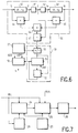
- FIG. 8 represents the diagram of a conventional structure of a correlator. It consists of systolic networks of a.b cells where a and b are the dimensions of the search window. Each cell contains a register R which stores the value of a sample and an elementary processor P, connected to the register R, which calculates the correlation function.
- the correlator includes as many cells as the window contains pixels to be analyzed. Each cell has a determined position in relation to the window, therefore a specific displacement vector.
- Figure 8 shows a 9 cell correlator.
- a first row contains cells R11 / P11 to R13 / P13
- a second row contains cells R21 / P21 to R23 / P23
- a third row contains cells R31 / P31 to R33 / P33.
- Each register is linked to its four closest neighbors by 3 receiving links and 3 sending links.
- the register R22 receives data from the registers R12, R12, R32.
- the same register R22 delivers data to the registers R12, R23, R32.
- Each register successively contains the data relating to all the pixels of a block to be analyzed.
- the processor assigned to said register calculates each time the correlation function between this data and the ECH value of the current sample which is distributed to all the processors.
- cd cycles are required for each processor to accumulate the total of the distortion function relating to a block to be analyzed.
- the value of the sample of the current block is broadcast to all the processors and the contents of the registers R are shifted by one step so that for all processors there is always the same displacement D between the data in the register R and the data broadcast.
- Ancillary members (not shown) make it possible to determine the processor delivering the best correlation and to deduce therefrom the displacement vector by the position of this best processor in the network. Ab cells operating on cd cycles are therefore required.
- a processor is assigned to a register to process all the pixels of a current block. According to the invention, this number of pixels to be processed is limited, from which arrangements are possible to obtain a gain either on the speed for a substantially similar hardware size, or on the size of the hardware for a substantially constant speed.
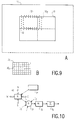
- FIGS. 9A, 9B schematically represent the processing which is carried out.
- FIG. 9B represents a current block 22 which is subdivided into 6 zones, for example the zone 221, themselves formed of pixels.
- a zone contains 9 pixels in this example from which the reference pixels are selected.
- a window to be treated 13 is represented.
- the processing of the entire image consists of performing successive treatments on a series of such windows.
- the correlation calculation consists in correlating pixel by pixel the current block 22 with each block to be treated constituting the window, for example block 12. All the blocks to be treated included in the window are obtained by sliding a step of 1 pixel successively in both directions. Block 12 slides one pixel successively according to block 121 (dots) then according to block 122 (cross). They are slightly vertically offset to be able to represent them.
- the correlation calculation with the blocks to be processed takes place at two levels.
- the correlation is calculated for the pixels of each block to be processed (in a window) having the same relative position in the block, that is to say for the same area at the top left in the block. Intermediate results are thus obtained concerning a particular zone for all the blocks. The calculation then relates to the next zone according to the same process.
- the treatment is schematized as follows:
- Running calculations in this order has the advantage of reducing data exchanges between registers, which simplifies the architecture and reduces calculation times.
- FIG. 10 represents the basic organs necessary for the progress of the correlation calculations.
- the diagram represents only one processor and one register but the situation is the same for the other processors and the other registers.
- Any register 40 is connected to other neighboring registers, for example in the four directions N, S, E, W by bidirectional or unidirectional buses depending on the architecture used. These data transfers between the registers are controlled by control means 71 common to all the registers.
- a processor 72 is connected to several of these registers by connections I1, I2, I3 ... which transmit the data from the registers.
- the processor 72 operating the calculations in successive stages must temporarily store intermediate results relating to the zones, themselves subdivided according to the blocks. These intermediate results are stored in storage means 73.
- FIG. 11 represents the diagram of part of a correlator according to the invention which favors a reduction in the number of cells.
- a processor P with a single displacement vector but it is operated for several displacement vectors for example f displacements (therefore f registers).
- f displacements therefore f registers
- ab registers R and ab / f processors there are ab registers R and ab / f processors.
- each register is linked to its nearest neighboring registers and any processor (for example P81) receives the data stored in the surrounding registers (respectively R81, R82, R91, R92).
- FIG. 12 represents the diagram of a repetitive part of a correlator according to the invention which favors the gain in speed in the case of a division of the current blocks into zones.
- This diagram corresponds to areas of 4 pixels from which a single reference pixel is selected to operate the correlation.
- the processing which is to be carried out for a particular zone will be carried out by the members located inside the discontinuous reference frame 90.
- Each register is no longer directly linked to the register which precedes it and to that which follows it as in Figure 8 but the connections in both rows and columns skip every other register. This arrangement follows from the fact that by selecting a single pixel out of 4 pixels per zone, one pixel out of 2 must be skipped ( Figure 3D) in both directions.
- a selection signal SEL makes it possible to operate the processor on one of the four registers which surround it in which the values of the 4 pixels of the area are stored at a given time.
- the block contains c.d pixels from which n reference pixels are selected, c.d / n connections between each processor and the neighboring registers are therefore necessary.
- the ECH value of the sample is simultaneously broadcast to all processors to calculate the correlation. With a window of a.b blocks, a correlator of a.b cells operating on n cycles is required.
- Each processor delivers the result of its calculation on its own output, for example S51 for the processor P51.
Landscapes
- Engineering & Computer Science (AREA)
- Multimedia (AREA)
- Signal Processing (AREA)
- Computer Vision & Pattern Recognition (AREA)
- Physics & Mathematics (AREA)
- General Physics & Mathematics (AREA)
- Theoretical Computer Science (AREA)
- Image Analysis (AREA)
- Compression Or Coding Systems Of Tv Signals (AREA)
- Image Processing (AREA)
Applications Claiming Priority (2)
| Application Number | Priority Date | Filing Date | Title |
|---|---|---|---|
| FR9016104 | 1990-12-21 | ||
| FR9016104A FR2670923A1 (fr) | 1990-12-21 | 1990-12-21 | Dispositif de correlation. |
Publications (2)
| Publication Number | Publication Date |
|---|---|
| EP0492702A1 true EP0492702A1 (de) | 1992-07-01 |
| EP0492702B1 EP0492702B1 (de) | 1998-12-09 |
Family
ID=9403535
Family Applications (1)
| Application Number | Title | Priority Date | Filing Date |
|---|---|---|---|
| EP91203285A Expired - Lifetime EP0492702B1 (de) | 1990-12-21 | 1991-12-13 | Korrelationsvorrichtung |
Country Status (5)
| Country | Link |
|---|---|
| US (1) | US5247586A (de) |
| EP (1) | EP0492702B1 (de) |
| JP (1) | JP3036937B2 (de) |
| DE (1) | DE69130602T2 (de) |
| FR (1) | FR2670923A1 (de) |
Families Citing this family (31)
| Publication number | Priority date | Publication date | Assignee | Title |
|---|---|---|---|---|
| WO1993023816A1 (en) * | 1992-05-18 | 1993-11-25 | Silicon Engines Inc. | System and method for cross correlation with application to video motion vector estimation |
| US6002431A (en) * | 1993-03-03 | 1999-12-14 | Goldstar Co., Ltd. | Video correction apparatus for camcorder |
| US5347311A (en) * | 1993-05-28 | 1994-09-13 | Intel Corporation | Method and apparatus for unevenly encoding error images |
| BE1007252A3 (nl) * | 1993-06-29 | 1995-05-02 | Philips Electronics Nv | Bewegingscompensator. |
| US5598514A (en) * | 1993-08-09 | 1997-01-28 | C-Cube Microsystems | Structure and method for a multistandard video encoder/decoder |
| JP2590705B2 (ja) * | 1993-09-28 | 1997-03-12 | 日本電気株式会社 | 動き補償予測装置 |
| JP3031152B2 (ja) * | 1993-12-24 | 2000-04-10 | 日本電気株式会社 | 動き予測プロセッサ及び動き予測装置 |
| DE4344924A1 (de) * | 1993-12-30 | 1995-08-10 | Thomson Brandt Gmbh | Verfahren und Vorrichtung zur Bewegungsschätzung |
| US5777690A (en) * | 1995-01-20 | 1998-07-07 | Kabushiki Kaisha Toshiba | Device and method for detection of moving obstacles |
| KR0171146B1 (ko) * | 1995-03-18 | 1999-03-20 | 배순훈 | 특징점을 이용한 움직임 벡터 검출 장치 |
| EP0820030B1 (de) * | 1995-03-31 | 2003-07-02 | SHIBATA, Tadashi | Halbleiterfunktionsschaltung |
| US5910909A (en) * | 1995-08-28 | 1999-06-08 | C-Cube Microsystems, Inc. | Non-linear digital filters for interlaced video signals and method thereof |
| US5764283A (en) * | 1995-12-29 | 1998-06-09 | Lucent Technologies Inc. | Method and apparatus for tracking moving objects in real time using contours of the objects and feature paths |
| US6008851A (en) * | 1996-05-23 | 1999-12-28 | The Regents Of The University Of California | Method and apparatus for video data compression |
| US5689562A (en) * | 1996-07-16 | 1997-11-18 | Ericsson, Inc. | Method for transmitting superimposed image data in a radio frequency communication system |
| US6016163A (en) * | 1997-03-12 | 2000-01-18 | Scientific-Atlanta, Inc. | Methods and apparatus for comparing blocks of pixels |
| US5930292A (en) * | 1997-04-21 | 1999-07-27 | Motorola, Inc. | Method and apparatus for improved autocorrelation in biphase modulated pseudorandom noise coded systems using tri-state demodulation |
| US6097851A (en) * | 1998-03-31 | 2000-08-01 | Agilent Technologies | Low latency correlation |
| US6771264B1 (en) * | 1998-08-20 | 2004-08-03 | Apple Computer, Inc. | Method and apparatus for performing tangent space lighting and bump mapping in a deferred shading graphics processor |
| AU5580799A (en) | 1998-08-20 | 2000-03-14 | Apple Computer, Inc. | Graphics processor with pipeline state storage and retrieval |
| WO2002009419A2 (en) * | 2000-07-20 | 2002-01-31 | Giant Leap Ahead Limited | Method and apparatus for determining motion vectors in dynamic images |
| FR2838849A1 (fr) * | 2002-04-17 | 2003-10-24 | St Microelectronics Sa | Determination de l'orientation des sillons d'une empreinte digitale |
| US7599044B2 (en) | 2005-06-23 | 2009-10-06 | Apple Inc. | Method and apparatus for remotely detecting presence |
| TWI288353B (en) * | 2004-12-24 | 2007-10-11 | Lite On Semiconductor Corp | Motion detection method |
| FR2886020B1 (fr) * | 2005-05-19 | 2007-10-19 | Eurocopter France | Systeme d'estimation de la vitesse d'un aeronef et son application a la detection d'obstacles |
| US9298311B2 (en) * | 2005-06-23 | 2016-03-29 | Apple Inc. | Trackpad sensitivity compensation |
| US7577930B2 (en) | 2005-06-23 | 2009-08-18 | Apple Inc. | Method and apparatus for analyzing integrated circuit operations |
| US7864982B2 (en) * | 2005-08-22 | 2011-01-04 | Samsung Electronics Co., Ltd. | Displacement and tilt detection method for a portable autonomous device having an integrated image sensor and a device therefor |
| US7433191B2 (en) | 2005-09-30 | 2008-10-07 | Apple Inc. | Thermal contact arrangement |
| US7598711B2 (en) | 2005-11-23 | 2009-10-06 | Apple Inc. | Power source switchover apparatus and method |
| JP2010288003A (ja) * | 2009-06-10 | 2010-12-24 | Sanyo Electric Co Ltd | 動き検出装置 |
Citations (1)
| Publication number | Priority date | Publication date | Assignee | Title |
|---|---|---|---|---|
| EP0368151A2 (de) * | 1988-11-05 | 1990-05-16 | ANT Nachrichtentechnik GmbH | Verfahren zur Bestimmung von Suchpositionen zur Bewegungsschätzung |
Family Cites Families (3)
| Publication number | Priority date | Publication date | Assignee | Title |
|---|---|---|---|---|
| DE368151C (de) * | 1923-02-02 | Heinrich Hildebrand | Explosionssicheres Gittersieb | |
| US4937878A (en) * | 1988-08-08 | 1990-06-26 | Hughes Aircraft Company | Signal processing for autonomous acquisition of objects in cluttered background |
| US5109438A (en) * | 1990-04-25 | 1992-04-28 | Hughes Aircraft Company | Data compression system and method |
-
1990
- 1990-12-21 FR FR9016104A patent/FR2670923A1/fr active Pending
-
1991
- 1991-12-12 US US07/806,023 patent/US5247586A/en not_active Expired - Fee Related
- 1991-12-13 DE DE69130602T patent/DE69130602T2/de not_active Expired - Fee Related
- 1991-12-13 EP EP91203285A patent/EP0492702B1/de not_active Expired - Lifetime
- 1991-12-20 JP JP3338845A patent/JP3036937B2/ja not_active Expired - Fee Related
Patent Citations (1)
| Publication number | Priority date | Publication date | Assignee | Title |
|---|---|---|---|---|
| EP0368151A2 (de) * | 1988-11-05 | 1990-05-16 | ANT Nachrichtentechnik GmbH | Verfahren zur Bestimmung von Suchpositionen zur Bewegungsschätzung |
Non-Patent Citations (3)
| Title |
|---|
| NEURAL NETWORKS; PERGAMON PRESS vol. 2, 1989, OXFORD (GB) pages 459 - 473; TERENCE D. SANGER: 'Optimal Unsupervised Learning in a Single-Layer Linear Feedforward Neural' * |
| PARALLEL COMPUTING. vol. 8, no. 1-3, Octobre 1988, AMSTERDAM NL pages 3 - 17; A. KASHKO ET AL.: 'Parallel matching and reconstruction algorithms in computer vision' * |
| PROCEEDINGS OF THE CONFERENCE ON COMPUTER VISION AND PATTERN RECOGNITION, WASHINGTON, JUIN 83 (US) ;IEEE PRESS , NEW YORK (US) pages 432 - 441; FRANK GLAZER: 'Scene matching by hierarchical correlation' * |
Also Published As
| Publication number | Publication date |
|---|---|
| JP3036937B2 (ja) | 2000-04-24 |
| JPH04294469A (ja) | 1992-10-19 |
| US5247586A (en) | 1993-09-21 |
| FR2670923A1 (fr) | 1992-06-26 |
| DE69130602T2 (de) | 1999-06-24 |
| DE69130602D1 (de) | 1999-01-21 |
| EP0492702B1 (de) | 1998-12-09 |
Similar Documents
| Publication | Publication Date | Title |
|---|---|---|
| EP0492702B1 (de) | Korrelationsvorrichtung | |
| EP0248729B1 (de) | Rechner für monodimensionelle Kosinus-Transformationen und Bildkodier- und -dekodiergeräte, welche solche Rechner benutzen | |
| EP0330279A1 (de) | Einrichtung zur raumzeitlichen Unterabtastung von digitalen Videosignalen, die eine Folge verschachtelter oder sequentieller Bilder darstellen, Übertragungssystem von Fernsehbildern mit hoher Auflösung mit einer solchen Einrichtung und Stufen zum Senden und Empfangen in einem solchen System | |
| EP0369854A1 (de) | Verfahren und Schaltung zur Blockverarbeitung von zweidimensionalen Signalen in beweglichen Bildern | |
| EP0347984A1 (de) | Verarbeitungssystem für Fernsehbilder mit Bewegungseinschätzer und verminderter Datenrate | |
| EP0717372B1 (de) | Verfahren zum Auswählen von Bewegungsvektoren und Bildverarbeitungsvorrichtung zur Durchführung des Verfahrens | |
| EP0318121B1 (de) | Verfahren und Vorrichtung zum Abschätzen und Kompensieren der Bewegung in einer Bildsequenz und Bildtransmissionssystem mit einer solchen Vorrichtung | |
| EP0778544B1 (de) | Verfahren zur Datenverarbeitung in matrixförmigen Netzwerken in einem Bewegungsschätzungssystem | |
| EP0332553A1 (de) | Verfahren zur Wiederzuordnung der Wahl eines Unterabtastungsverfahrens nach dem Kriterium einer Datenraten-Reduktion einer Folge von Hilfsdaten, die zur Rekonstruktion eines unterabgetasteten, elektronischen Bildes dienen | |
| EP0286192B1 (de) | Verfahren und Gerät zur Bewegungsabschätzung in einer Bildfolge | |
| EP0294282B1 (de) | Verfahren zur temporalen Interpolation von Bildern und Einrichtung zur Durchführung dieses Verfahrens | |
| EP0224957B1 (de) | Verfahren und Einrichtung zur Bewegungsabschätzung in einer Bildfolge | |
| EP1603341B1 (de) | Verfahren und Anordnung für Bildinterpolierungssysteme mit Bewegungsschätzung und -kompensation | |
| EP0063990B1 (de) | Verfahren zur Bildübertragung mit beschränktem Datafluss; Übertragungssystem zur Durchführung dieses Verfahrens | |
| WO2007135309A2 (fr) | Procede de codage et systeme d'affichage sur un ecran d'une maquette numerique d'un objet sous forme d'une image de synthese | |
| EP0350122A1 (de) | Verfahren und Einrichtungen zur Kodierung und Dekodierung von Fernsehbildern mit hoher Auflösung und Übertragungssysteme mit solchen Einrichtungen | |
| FR2699780A1 (fr) | Dispositif de traitement récursif de signal vidéo comprenant une pluralité de branches. | |
| EP1591962A2 (de) | Verfahren und Anordnung zur Erzeugung von Kandidatenvektoren für Bildinterpolierungssysteme, die Bewegungsabschätzung und -kompensation verwenden | |
| EP0674444B1 (de) | Filter für Matrix von Pixeln | |
| EP1596607B1 (de) | Verfahren und Anordnung zur Erzeugung von Kandidatenvektoren für Bildinterpolierungssyteme, die Bewegungsabschätzung und -kompensation verwenden | |
| EP1691342B1 (de) | Verfahren und Vorrichtung zur Bildverarbeitung | |
| FR2700037A1 (fr) | Dispositif d'estimation hiérarchique du mouvement de séquence d'images. | |
| FR2717648A1 (fr) | Procédé et dispostif d'estimation de mouvement entre images de télévision d'une séquence d'images. | |
| WO2024240497A1 (fr) | Procédé et dispositif de codage et décodage d'images. | |
| WO2022253932A1 (fr) | Procede de traitement de données de pixels, dispositif et programme correspondant |
Legal Events
| Date | Code | Title | Description |
|---|---|---|---|
| PUAI | Public reference made under article 153(3) epc to a published international application that has entered the european phase |
Free format text: ORIGINAL CODE: 0009012 |
|
| AK | Designated contracting states |
Kind code of ref document: A1 Designated state(s): DE FR GB |
|
| 17P | Request for examination filed |
Effective date: 19921221 |
|
| RAP1 | Party data changed (applicant data changed or rights of an application transferred) |
Owner name: PHILIPS ELECTRONICS N.V. Owner name: LABORATOIRES D'ELECTRONIQUE PHILIPS S.A.S. |
|
| 17Q | First examination report despatched |
Effective date: 19960620 |
|
| GRAG | Despatch of communication of intention to grant |
Free format text: ORIGINAL CODE: EPIDOS AGRA |
|
| GRAG | Despatch of communication of intention to grant |
Free format text: ORIGINAL CODE: EPIDOS AGRA |
|
| GRAG | Despatch of communication of intention to grant |
Free format text: ORIGINAL CODE: EPIDOS AGRA |
|
| GRAH | Despatch of communication of intention to grant a patent |
Free format text: ORIGINAL CODE: EPIDOS IGRA |
|
| RAP3 | Party data changed (applicant data changed or rights of an application transferred) |
Owner name: KONINKLIJKE PHILIPS ELECTRONICS N.V. Owner name: LABORATOIRES D'ELECTRONIQUE PHILIPS S.A.S. |
|
| GRAH | Despatch of communication of intention to grant a patent |
Free format text: ORIGINAL CODE: EPIDOS IGRA |
|
| GRAA | (expected) grant |
Free format text: ORIGINAL CODE: 0009210 |
|
| AK | Designated contracting states |
Kind code of ref document: B1 Designated state(s): DE FR GB |
|
| REF | Corresponds to: |
Ref document number: 69130602 Country of ref document: DE Date of ref document: 19990121 |
|
| GBT | Gb: translation of ep patent filed (gb section 77(6)(a)/1977) |
Effective date: 19990201 |
|
| PLBE | No opposition filed within time limit |
Free format text: ORIGINAL CODE: 0009261 |
|
| STAA | Information on the status of an ep patent application or granted ep patent |
Free format text: STATUS: NO OPPOSITION FILED WITHIN TIME LIMIT |
|
| 26N | No opposition filed | ||
| REG | Reference to a national code |
Ref country code: FR Ref legal event code: TP |
|
| REG | Reference to a national code |
Ref country code: GB Ref legal event code: IF02 |
|
| PGFP | Annual fee paid to national office [announced via postgrant information from national office to epo] |
Ref country code: FR Payment date: 20021223 Year of fee payment: 12 |
|
| PGFP | Annual fee paid to national office [announced via postgrant information from national office to epo] |
Ref country code: GB Payment date: 20021224 Year of fee payment: 12 |
|
| PGFP | Annual fee paid to national office [announced via postgrant information from national office to epo] |
Ref country code: DE Payment date: 20030217 Year of fee payment: 12 |
|
| PG25 | Lapsed in a contracting state [announced via postgrant information from national office to epo] |
Ref country code: GB Free format text: LAPSE BECAUSE OF NON-PAYMENT OF DUE FEES Effective date: 20031213 |
|
| PG25 | Lapsed in a contracting state [announced via postgrant information from national office to epo] |
Ref country code: DE Free format text: LAPSE BECAUSE OF NON-PAYMENT OF DUE FEES Effective date: 20040701 |
|
| GBPC | Gb: european patent ceased through non-payment of renewal fee |
Effective date: 20031213 |
|
| PG25 | Lapsed in a contracting state [announced via postgrant information from national office to epo] |
Ref country code: FR Free format text: LAPSE BECAUSE OF NON-PAYMENT OF DUE FEES Effective date: 20040831 |
|
| REG | Reference to a national code |
Ref country code: FR Ref legal event code: ST |