EP0492995A1 - Elément de renforcé à évidement conique en spirale et moment de flexion amélioré - Google Patents
Elément de renforcé à évidement conique en spirale et moment de flexion amélioré Download PDFInfo
- Publication number
- EP0492995A1 EP0492995A1 EP91311815A EP91311815A EP0492995A1 EP 0492995 A1 EP0492995 A1 EP 0492995A1 EP 91311815 A EP91311815 A EP 91311815A EP 91311815 A EP91311815 A EP 91311815A EP 0492995 A1 EP0492995 A1 EP 0492995A1
- Authority
- EP
- European Patent Office
- Prior art keywords
- taper
- terminus
- end portion
- vehicle door
- degrees
- Prior art date
- Legal status (The legal status is an assumption and is not a legal conclusion. Google has not performed a legal analysis and makes no representation as to the accuracy of the status listed.)
- Withdrawn
Links
- 238000005452 bending Methods 0.000 claims abstract description 15
- 230000007704 transition Effects 0.000 claims description 30
- 230000002093 peripheral effect Effects 0.000 claims description 13
- 239000000463 material Substances 0.000 description 11
- CURLTUGMZLYLDI-UHFFFAOYSA-N Carbon dioxide Chemical compound O=C=O CURLTUGMZLYLDI-UHFFFAOYSA-N 0.000 description 4
- 238000003466 welding Methods 0.000 description 3
- 229910000831 Steel Inorganic materials 0.000 description 2
- 229910002092 carbon dioxide Inorganic materials 0.000 description 2
- 239000001569 carbon dioxide Substances 0.000 description 2
- 238000011156 evaluation Methods 0.000 description 2
- 238000004519 manufacturing process Methods 0.000 description 2
- 239000010959 steel Substances 0.000 description 2
- 208000027418 Wounds and injury Diseases 0.000 description 1
- 239000003795 chemical substances by application Substances 0.000 description 1
- 230000006378 damage Effects 0.000 description 1
- 230000007423 decrease Effects 0.000 description 1
- 230000003247 decreasing effect Effects 0.000 description 1
- 239000000446 fuel Substances 0.000 description 1
- 208000014674 injury Diseases 0.000 description 1
- 239000002184 metal Substances 0.000 description 1
- 230000002787 reinforcement Effects 0.000 description 1
- 239000002699 waste material Substances 0.000 description 1
Images



Classifications
-
- B—PERFORMING OPERATIONS; TRANSPORTING
- B60—VEHICLES IN GENERAL
- B60J—WINDOWS, WINDSCREENS, NON-FIXED ROOFS, DOORS, OR SIMILAR DEVICES FOR VEHICLES; REMOVABLE EXTERNAL PROTECTIVE COVERINGS SPECIALLY ADAPTED FOR VEHICLES
- B60J5/00—Doors
- B60J5/04—Doors arranged at the vehicle sides
- B60J5/042—Reinforcement elements
- B60J5/0422—Elongated type elements, e.g. beams, cables, belts or wires
- B60J5/0437—Elongated type elements, e.g. beams, cables, belts or wires characterised by the attachment means to the door, e.g. releasable attachment means
-
- B—PERFORMING OPERATIONS; TRANSPORTING
- B60—VEHICLES IN GENERAL
- B60J—WINDOWS, WINDSCREENS, NON-FIXED ROOFS, DOORS, OR SIMILAR DEVICES FOR VEHICLES; REMOVABLE EXTERNAL PROTECTIVE COVERINGS SPECIALLY ADAPTED FOR VEHICLES
- B60J5/00—Doors
- B60J5/04—Doors arranged at the vehicle sides
- B60J5/042—Reinforcement elements
- B60J5/0422—Elongated type elements, e.g. beams, cables, belts or wires
- B60J5/0438—Elongated type elements, e.g. beams, cables, belts or wires characterised by the type of elongated elements
- B60J5/0443—Beams
- B60J5/0444—Beams characterised by a special cross section
Definitions
- This invention relates to vehicle door impact beams.
- Structural reinforcements added to the doors of vehicles are commonly called impact beams, intrusion beams, guard beams, or door beams.
- Vehicle impact door beams have been provided in a variety of cross sectional configurations, including I-beam, hat section, and tubular. Each of these has effectiveness, if property designed, with the tubular beam considered to have certain advantages, see especially US-A-4,636,608 and US-A-4,708,390. Tapering the ends of the tubular beams has the advantages of 1) accommodating vehicle door curvature, 2) saving material, 3) lowering beam weight, and 4) potentially enabling the beam to be nestable (i.e. the material removed from the end of one beam can form the opposite end of the second beam, etc.).
- the basic function of the impact beam is to minimize injury to persons in the vehicle during side collision.
- Side collision is characterized by an impact load or force applied generally horizontally, transverse to the vehicle door, generally normal to the horizontal beam, thereby applying a bending moment to the impact beam which extends across the door within the confines of the inner and outer door shells.
- the beam should have moment capacity, at each location along its length, greater than the bending moment caused thereat by the specified impact load.
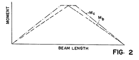
- the length of the taper cut on both ends has in the past been primarily determined by stock length and beam length, in efforts to avoid excess scrap. Performance has been based on door stiffness and strength. Since the greatest moment would be at the centre of the beam, this would be expected to be the point at which yielding first occurs. Door strength tests are conducted with a ram loaded at the beam centre. Determining the length of the cut by stock length and beam length can lead to excessive taper length, and result in a tendency to fail, i.e., buckle, in the taper itself rather than in the main central portion of the beam. It has now been found that in some portions of prior taper cuts, the moment capacity M C dips below the bending moment M B so that the moment ratio M R is less than one.
- the ends When the end portions of tubular beams are provided with a taper cut, the ends have only a fraction of the tube remaining there, i.e., a relatively small included angle with portions having an included angle of less than 180 degrees, and other portions having an included angle greater than 180 degrees.
- the “included angle” is that angle between two lines extending from the centre line of the tubular beam to the taper edges on opposite sides of the centre line, to indicate the degree of peripheral wall remaining.
- I x the moment of inertia at that point
- I F the moment of inertia assuming the tube to be a full tube for included angles equal to 180 degrees.
- the reactive force at the tapered section is offset from the applied force causing a couple and hence twisting or torqueing the tapered section, which may cause buckling.
- One feature of the present invention is to provide a nestable, tubular, impact door beam for a vehicle, having tapered ends of special configuration effecting near optimum moment capacity combined with less material cost.
- the moment capacity at any incremental part of the beam, even along the taper cut ends, is assured to be greater than the bending moment, but not greatly in excess of the bending moment so as to waste material.
- the moment capacity is controlled in a fashion that the novel beam still has the nestability advantage of prior tubular beams, i.e., two beam ends formed with one cut.
- the length of the cut can be increased while still providing an effective door beam with adequate moment capacity.
- the beam having means comprising a predetermined partial circumference with an included angle sufficient at all positions along the length of the tapered end portions for achieving a moment capacity (Mc), at all said positions, greater than the bending moment (Mb) at said positions; each said tapered end portion having a sloped central body and a pair of parabolic, body straddling transitions, one toward said outer terminus and the other toward said central portion; said wall surfaces of said one parabolic transition having a convex curvilinear parabolic configuration, and said wall surfaces of said other parabolic transition having a concave curvilinear parabolic configuration.
- Mc moment capacity
- Mb bending moment
- the taper surfaces said taper surfaces in said first end portion both extend spirally from said inner terminus in said first end portion through an angle of about 90 degrees to said outer terminus of said first end portion; and said taper surfaces in said second end portion both extend spirally from said inner terminus in said second end portion through an angle of about 90 degrees to said outer terminus of said second end portion.
- each taper cut includes a sloped central body and a pair of curvilinear, parabolic end transitions.
- the present invention also provides a vehicle door impact beam of the tapered end type, having novel structure achieving increased moment capacity allowing use of less beam material with longer tapered end portions.
- the taper surfaces spiral about the central axis of the tube, increasing the moment of inertia in the plane perpendicular to the applied load.
- the structure enables longer taper cuts to be employed while maintaining adequate moment of inertia, thereby reducing weight and the amount of material required. Yet, it has ease of manufacture.
- the spiral on each end portion extends through a total spiral angle of about 90°.
- the beam ends preferably fit within concave recesses in the brackets, sometimes called extensions, when they are welded in place.
- Each tapered end has an inner terminus and an outer terminus.
- the inner termini of the two ends are 180 degrees displaced from each other.
- the outer termini of the two ends are on the same side of the beam, i.e., displaced zero degrees from each other.
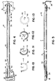
- the impact beam assembly 1 there depicted typically includes the impact beam 2 itself and a pair of mounting plates 4, shown in phantom, to which the beam is secured as by welding, the mounting plates being secured to the door frame of the vehicle by welding, bolts, or the like, as is desired.
- Beam 2 is initially of a tubular cylindrical body of high grade steel, e.g., "BTR 110" from Benteler Werke AG, Paderhorn, Federal Republic of Germany. It may be formed as set forth in US-A-4,210,467.
- the tubular beam has a central axis and a wall thickness. Beam 2 also has specially formed and configurated taper cut end portions.
- the end extensions or mounting brackets 4 may vary considerably in configuration, depending upon the vehicle model and size into which the structure is to be mounted. These brackets may have stamped recess cavities for receiving the ends of the beam, and appropriate orifices or fasteners to secure them to the door frame. Typical brackets are shown in US-A-Patent 4,708,390, as one example.
- the tapered end portions of the beam may be formed by being laser cut while causing relative rotation between the beam and the laser and relative axial movement between the beam and the laser, the laser preferably being oriented directly toward the axis of the beam.
- a suitable laser source (not shown) can be a 1250 watt carbon dioxide cutting laser, with the laser beam being directed toward the axis of the tubular workpiece by being reflected by mirrors, as explained in U.S. Patent 4,708,390.
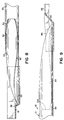
- each taper cut end portion includes a central, sloped cut body and a pair of end transitions (Fig. 3).
- One of the end transitions adjacent the central portion of the beam is concavely curved while the other end transition adjacent the outer terminus is convexly curved.
- the metal tube is cut to cause the wall thickness of the tube to be exposed.
- Each portion of the exposed wall surface is preferably oriented toward, or almost toward, the axis of the cylindrical tube.
- the fragmentary distance along the total cut length TL, at which an evaluation is to be made, is designated L.
- the total taper length TL is divided into fifths, i.e., 0.2 TL lengths. Other fractions could be employed.
- the total taper length TL is the linear length of the tube over which the cut extends.
- IA included angle between the two mirror image opposite sides of the cut (see Figs 1A - 1D).
- the taper cut has an outer terminus at the end of the beam, and an inner terminus adjacent the central portion of the beam.
- the beam has a greater peripheral partial circumference adjacent this central portion, and a smaller peripheral partial circumference adjacent the outer terminus.
- the moment capacity M C is greater at all points along the beam than the bending moment M B , i.e., the moment ratio M R of M C divided by M B is equal to or greater than one. It is also important to have the beam be nestable, i.e., two beam ends cut with the same taper cut. The included angle should not be greater than a certain amount if nestable character is to be achieved.
- the slope of the body portion is linear, or close thereto.
- the two transitions are parabolic, or close thereto.
- the resulting tubular beam is at or near optimum beam capacity over its length, including its taper cut ends, and is nestable.
- the vehicle impact beam and mount assembly 10 (Figs. 4 and 5) comprises an elongated, taper cut, tubular impact beam 12, and first and second mounts, brackets or extensions 14 and 16. These mounts may be of varied configuration to accommodate the particular make, size and model of the vehicle, i.e., automobile or truck, involved. Mounts 14 and 16 are typical of those employed. Mount 14 is shown to include a generally planar portion 18 having an elongated, concave, curvilinear, semicylindrical recess 20 therein, of an inner diameter generally corresponding to the outer diameter of beam 12.
- Mount 16 likewise has a generally planar portion 22 and an elongated, concave, curvilinear, semicylindrical cavity 24 for receiving the beam end. Bracket 16 is also shown with a transverse flange 26 (Fig. 2) for fitting a particular door style. These mounts are secured to the door frame by bolting or welding. Elongated cavity 24 also has an inner diameter generally comparable to the outer diameter of beam 12 for receiving the beam end. The beam ends are welded to brackets 14 and 16 at zones 15 (Figs. 3 and 4).
- the impact beam comprises an elongated, tubular member, generally cylindrical in configuration, having a central portion 30, a first end portion 32, and a second opposite end portion 34. It is preferably made of steel such as that in US-A-4,210,467, commonly called BTR 110.
- the peripheral wall of each of these end portions is taper cut along the length of the end portion in a manner to expose a pair of opposite taper surfaces, specifically taper surfaces 40 and 42 on end portion 32 and taper surfaces 44 and 46 on end portion 34. Each taper surface extends through the thickness of the wall. They are on both sides of the central axis of the tube, to provide the first and second taper surfaces on opposite sides of and equally spaced from the central axis of the beam.
- each pair of taper surfaces join each other at the inner and outer termini of the cut.
- These taper surfaces preferably are aligned throughout their length with the central axis of the beam such that, at each increment along the taper surface length, a plane passing through that increment will also pass through the central axis of the beam.
- the taper cut on end portion 32 has an inner axial terminus 50 and an outer axial terminus 52.
- the taper cut on end portion 34 has an inner axial terminus 54 and an outer axial terminus 56.
- each inner terminus is an arc in a plane transverse to, and preferably normal to, the beam axis.
- Each outer terminus is an arc in a plane transverse to, and preferably normal to, the beam axis.
- the spiral in each end portion, between the inner and outer termini optimally extends through an angle of about 90 degrees.
- One portion, here the first end portion 32 has the inner terminus on the top of the beam, with the spiral extending counterclockwise.
- End portion 34 has the inner terminus on the opposite side of the beam, i.e., here the bottom of the beam, displaced 180 degrees from the inner terminus on the first end portion.
- the spiral on depicted end portion 34 also extends counterclockwise, i.e., the two opposite tapered end portions spiral in the same angular direction.
- Each tapered end portion has an outer part, i.e., nearer the outer terminus, having an included angle less than 180 degrees, and an inner part, i.e., nearer the inner terminus, having an included angle greater than 180 degrees.
- the outer part is prone to be unstable if impact force is edge applied as in Fig. 10, due to torque-caused buckling, but is stable when impact force is substantially face applied as in Fig. 11.
- This outer part is provided with additional moment capacity by the attached mounting plate or extension 14 or 16.
- the spiral configuration of the tapered end causes the impact force to be fully face applied at the outer terminus, and fully edge applied at the inner terminus, with a gradual shift between the two over the length of the taper cut. Generally midway between the termini, some torque results from impact force, but it is relatively small.
- the respective taper cuts are preferably formed utilizing a conventional cutting laser beam oriented toward the centre line axis 17 of impact beam 12 while the impact beam is rotationally and axially advanced relative to the laser beam to sequentially cut one side, the inner terminus, and then the other side.
- a suitable cutting source (not shown) can be a 1250 watt conventional carbon dioxide cutting laser or the equivalent.
- this uniquely configured, tubular, tapered end beam is capable of providing increased moment capacity under impact force.
- this longer taper achieves adequate strength to satisfy the impact requirements of governmental standards while saving considerable material and weight, and enabling fit inside thin and/or curvilinear doors more readily.
- the fact that the beam can be made lighter in weight not only saves beam material, but also decreases vehicle weight for better economy of fuel usage.
- the beam is nestable, i.e., the material removed from one end of the beam during manufacture actually forms the opposite end, i.e., second end, of the next beam being formed.
- the fragmentary distance along the total cut length TL of either the first end portion 32 or the second end portion 34, at which an evaluation is to be made is designated L.
- the total taper length TL is divided into fifths, i.e., 0.2 TL lengths. Other fractions could be employed.
- the total taper length TL is the linear length of the tube over which the cut extends.
- IA included angle
- the beam has a greater peripheral,partial circumference adjacent the central beam portion, and a smaller peripheral partial circumference adjacent the outer terminus of the taper cut.
- the moment capacity M C at each increment along the length of the beam is made greater than the bending moment M B (Fig.52) so that impact will cause the beam to hinge near the centre of the beam rather than at the taper cut end portions.
- the included angle should not be excessive.
- each taper cut end portion has a central body and two body straddling transitions.
- the configuration of the central body and the two transitions of each taper cut are defined in terms of the included angle IA as set forth below.
- the shape of the central body is a linear slope, or close thereto, in a spiral, i.e., helix, while each of the two transitions is of parabolic curvature, or close thereto, in a spiral, i.e., helix.
- IA included angle at a particular location
- m slope of central body taper surface
- TL total taper length
- L the fraction of total taper length at a particular location
- Y the Y axis intercept of the body slope.
Landscapes
- Engineering & Computer Science (AREA)
- Mechanical Engineering (AREA)
- Body Structure For Vehicles (AREA)
Applications Claiming Priority (4)
| Application Number | Priority Date | Filing Date | Title |
|---|---|---|---|
| US07/631,099 US5118159A (en) | 1990-12-19 | 1990-12-19 | Optimized moment capacity nestable door beam |
| US631099 | 1990-12-19 | ||
| US07/717,543 US5123694A (en) | 1991-06-19 | 1991-06-19 | Spiral taper cut impact beam |
| US717543 | 1991-06-19 |
Publications (1)
| Publication Number | Publication Date |
|---|---|
| EP0492995A1 true EP0492995A1 (fr) | 1992-07-01 |
Family
ID=27091305
Family Applications (1)
| Application Number | Title | Priority Date | Filing Date |
|---|---|---|---|
| EP91311815A Withdrawn EP0492995A1 (fr) | 1990-12-19 | 1991-12-19 | Elément de renforcé à évidement conique en spirale et moment de flexion amélioré |
Country Status (2)
| Country | Link |
|---|---|
| EP (1) | EP0492995A1 (fr) |
| JP (1) | JP2696451B2 (fr) |
Cited By (5)
| Publication number | Priority date | Publication date | Assignee | Title |
|---|---|---|---|---|
| DE4307079A1 (de) * | 1993-03-06 | 1994-09-08 | Benteler Werke Ag | Verfahren zur Herstellung von Türaufprallträgern für Kraftfahrzeuge |
| DE19640568C2 (de) * | 1996-10-01 | 2000-05-11 | Benteler Werke Ag | Verfahren zur Herstellung von rohrförmigen Seitenaufprallträgern |
| US6382707B1 (en) * | 2000-10-09 | 2002-05-07 | Daimlerchrysler Corporation | Reinforced door assembly for a motor vehicle |
| US6568742B2 (en) * | 2001-08-30 | 2003-05-27 | Hyundai Motor Company | Rear door structure of vehicle |
| GB2556689A (en) * | 2016-10-20 | 2018-06-06 | Ford Global Tech Llc | Vehicle door beam assembly |
Citations (3)
| Publication number | Priority date | Publication date | Assignee | Title |
|---|---|---|---|---|
| EP0235091A2 (fr) * | 1986-02-25 | 1987-09-02 | Alusuisse-Lonza Services Ag | Porte de véhicule ayant un profilé de choc |
| DE3709489C1 (de) * | 1987-03-25 | 1988-07-14 | Aluminium Walzwerke Singen | Aufpralltraeger fuer Fahrzeugtueren,insbesondere fuer Tueren von Personenkraftwagen |
| EP0395621A1 (fr) * | 1989-03-28 | 1990-10-31 | Austria Metall Aktiengesellschaft | Poutre de protection antichoc pour portes et panneaux latéraux de carrosseries de véhicules automobiles |
-
1991
- 1991-12-11 JP JP3360870A patent/JP2696451B2/ja not_active Expired - Fee Related
- 1991-12-19 EP EP91311815A patent/EP0492995A1/fr not_active Withdrawn
Patent Citations (3)
| Publication number | Priority date | Publication date | Assignee | Title |
|---|---|---|---|---|
| EP0235091A2 (fr) * | 1986-02-25 | 1987-09-02 | Alusuisse-Lonza Services Ag | Porte de véhicule ayant un profilé de choc |
| DE3709489C1 (de) * | 1987-03-25 | 1988-07-14 | Aluminium Walzwerke Singen | Aufpralltraeger fuer Fahrzeugtueren,insbesondere fuer Tueren von Personenkraftwagen |
| EP0395621A1 (fr) * | 1989-03-28 | 1990-10-31 | Austria Metall Aktiengesellschaft | Poutre de protection antichoc pour portes et panneaux latéraux de carrosseries de véhicules automobiles |
Cited By (6)
| Publication number | Priority date | Publication date | Assignee | Title |
|---|---|---|---|---|
| DE4307079A1 (de) * | 1993-03-06 | 1994-09-08 | Benteler Werke Ag | Verfahren zur Herstellung von Türaufprallträgern für Kraftfahrzeuge |
| DE19640568C2 (de) * | 1996-10-01 | 2000-05-11 | Benteler Werke Ag | Verfahren zur Herstellung von rohrförmigen Seitenaufprallträgern |
| US6382707B1 (en) * | 2000-10-09 | 2002-05-07 | Daimlerchrysler Corporation | Reinforced door assembly for a motor vehicle |
| US6568742B2 (en) * | 2001-08-30 | 2003-05-27 | Hyundai Motor Company | Rear door structure of vehicle |
| GB2556689A (en) * | 2016-10-20 | 2018-06-06 | Ford Global Tech Llc | Vehicle door beam assembly |
| US10112463B2 (en) | 2016-10-20 | 2018-10-30 | Ford Global Technologies, Llc | Vehicle door beam assembly |
Also Published As
| Publication number | Publication date |
|---|---|
| JPH06171361A (ja) | 1994-06-21 |
| JP2696451B2 (ja) | 1998-01-14 |
Similar Documents
| Publication | Publication Date | Title |
|---|---|---|
| US5123694A (en) | Spiral taper cut impact beam | |
| US6082811A (en) | Reinforcement for vehicle hollow structural member, having decreasing-thickness end portions | |
| US5404690A (en) | Impact beam assembly method and apparatus | |
| US5540016A (en) | Structural beam | |
| EP0852191B1 (fr) | Structure d'absorbtion d'énergie pour véhicule | |
| US6290282B1 (en) | Structural beam for supporting and reinforcing a structure | |
| US5785376A (en) | Vehicle door beam | |
| US5580120A (en) | Vehicle door intrusion beam | |
| AU2002359354C1 (en) | Variable thickness tubular doorbeam | |
| US5560672A (en) | Energy absorbing beam | |
| EP1063135B1 (fr) | Pare-choc composé de plusieurs pièces | |
| EP0112825B1 (fr) | Poutre de protection et son procede de fabrication | |
| US6039387A (en) | Reinforcement device for side doors of automobiles | |
| EP1398247B1 (fr) | Profilés creux en alliage d'aluminium pour une carcasse d'une carrosserie | |
| AU617046B2 (en) | System for mixing and dispensing concrete | |
| US5370437A (en) | Universal impact beam tube pocket | |
| DE19725163A1 (de) | Energieabsorbierende Lenksäule | |
| EP0492995A1 (fr) | Elément de renforcé à évidement conique en spirale et moment de flexion amélioré | |
| IE880880L (en) | Impact absorber for vehicle doors | |
| US20040201255A1 (en) | Lightweight beam | |
| US5118159A (en) | Optimized moment capacity nestable door beam | |
| US5951097A (en) | Impact reinforcement for curved rails in motor vehicles | |
| US20040150249A1 (en) | Side impact beam | |
| JP3002508B2 (ja) | 車両用サイドインパクトビーム | |
| US5452545A (en) | Impact support for a door of a motor vehicle |
Legal Events
| Date | Code | Title | Description |
|---|---|---|---|
| PUAI | Public reference made under article 153(3) epc to a published international application that has entered the european phase |
Free format text: ORIGINAL CODE: 0009012 |
|
| AK | Designated contracting states |
Kind code of ref document: A1 Designated state(s): AT BE CH DE DK ES FR GB GR IT LI LU NL SE |
|
| 17P | Request for examination filed |
Effective date: 19921028 |
|
| 17Q | First examination report despatched |
Effective date: 19940203 |
|
| STAA | Information on the status of an ep patent application or granted ep patent |
Free format text: STATUS: THE APPLICATION IS DEEMED TO BE WITHDRAWN |
|
| 18D | Application deemed to be withdrawn |
Effective date: 19950317 |