EP0852191B1 - Structure d'absorbtion d'énergie pour véhicule - Google Patents
Structure d'absorbtion d'énergie pour véhicule Download PDFInfo
- Publication number
- EP0852191B1 EP0852191B1 EP97122783A EP97122783A EP0852191B1 EP 0852191 B1 EP0852191 B1 EP 0852191B1 EP 97122783 A EP97122783 A EP 97122783A EP 97122783 A EP97122783 A EP 97122783A EP 0852191 B1 EP0852191 B1 EP 0852191B1
- Authority
- EP
- European Patent Office
- Prior art keywords
- bracket
- energy absorbing
- absorbing structure
- structure according
- roofside rail
- Prior art date
- Legal status (The legal status is an assumption and is not a legal conclusion. Google has not performed a legal analysis and makes no representation as to the accuracy of the status listed.)
- Expired - Lifetime
Links
- 230000003014 reinforcing effect Effects 0.000 claims description 42
- 238000010521 absorption reaction Methods 0.000 claims description 15
- 229910052751 metal Inorganic materials 0.000 claims description 4
- 239000002184 metal Substances 0.000 claims description 4
- 238000006073 displacement reaction Methods 0.000 description 14
- 125000006850 spacer group Chemical group 0.000 description 6
- 229910000831 Steel Inorganic materials 0.000 description 2
- 238000000034 method Methods 0.000 description 2
- 230000004048 modification Effects 0.000 description 2
- 238000012986 modification Methods 0.000 description 2
- 239000010959 steel Substances 0.000 description 2
- 238000003466 welding Methods 0.000 description 2
- 229910052782 aluminium Inorganic materials 0.000 description 1
- XAGFODPZIPBFFR-UHFFFAOYSA-N aluminium Chemical compound [Al] XAGFODPZIPBFFR-UHFFFAOYSA-N 0.000 description 1
- 238000005452 bending Methods 0.000 description 1
- 230000008602 contraction Effects 0.000 description 1
- 230000000881 depressing effect Effects 0.000 description 1
- 230000000994 depressogenic effect Effects 0.000 description 1
- 238000010586 diagram Methods 0.000 description 1
- 230000002708 enhancing effect Effects 0.000 description 1
- 239000011347 resin Substances 0.000 description 1
- 229920005989 resin Polymers 0.000 description 1
Images




Classifications
-
- B—PERFORMING OPERATIONS; TRANSPORTING
- B60—VEHICLES IN GENERAL
- B60N—SEATS SPECIALLY ADAPTED FOR VEHICLES; VEHICLE PASSENGER ACCOMMODATION NOT OTHERWISE PROVIDED FOR
- B60N3/00—Arrangements or adaptations of other passenger fittings, not otherwise provided for
- B60N3/02—Arrangements or adaptations of other passenger fittings, not otherwise provided for of hand grips or straps
- B60N3/026—Arrangements or adaptations of other passenger fittings, not otherwise provided for of hand grips or straps characterised by the fixing means
-
- B—PERFORMING OPERATIONS; TRANSPORTING
- B60—VEHICLES IN GENERAL
- B60R—VEHICLES, VEHICLE FITTINGS, OR VEHICLE PARTS, NOT OTHERWISE PROVIDED FOR
- B60R21/00—Arrangements or fittings on vehicles for protecting or preventing injuries to occupants or pedestrians in case of accidents or other traffic risks
- B60R21/02—Occupant safety arrangements or fittings, e.g. crash pads
- B60R21/055—Padded or energy-absorbing fittings, e.g. seat belt anchors
Definitions
- the present invention relates to an energy absorbing structure for an automobile (see, for example, JP-A-08 113 162, corresponding to the preamble of claim 1.)
- Japanese Unexamined Patent Publication No. 7-232583 discloses an assist grip supporting structure for an automobile, in which the roofside rail includes a deformable portion to which the assist grip is connected, and the deformable portion deforms when a large outward load acts on the assist grip, to thereby provide energy absorption.
- outward refers to a direction from the compartment toward the outside and “inward” refers to a direction from the outside toward the compartment, in this specification.
- Japanese Unexamined Patent Publication No. 7-61304 discloses an assist grip supporting structure for an automobile in which the assist grip includes a deformable portion, and the deformable portion deforms when a large outward load acts on the assist grip, to thereby provide the energy absorption.
- the assist grip supporting structure disclosed in the former publication may decrease the rigidity of the roofside rail, and that in the latter publication may decrease the strength of the assist grip.
- U.S. Patent No. 5,529,344 discloses a seat belt anchor supporting structure for an automobile in which a bracket having a deformable portion is connected to a center pillar of the automobile, and the seat belt anchor is supported by the bracket.
- the deformable portion deforms when a large outward load acts on the seat belt anchor, to thereby provide the energy absorption.
- EP-A-0 800 956 Another energy absorbing structure is known from EP-A-0 800 956 which, however, constitutes prior art pursuant to Article 54(3) EPC only.
- an assist grip supporting structure which can provide energy absorption if the assist grip is applied to the seat belt anchor supporting structure, i.e., if the bracket having a deformable portion is connected to the roofside rail and the assist grip is connected to the deformable portion.
- the deformable portion of the bracket mentioned above must deform due to an outward load on the assist grip, the deformable portion may also deform due to an inward load on the assist grip. However, the large inward load may act on the assist grip in the normal use. If the deformable portion deforms inwardly, the assist grip is not supported firmly.
- An object of the present invention is to provide an energy absorbing structure of an automobile capable of supporting the assist grip firmly, while providing energy absorption for an outward load on the assist grip.
- an energy absorbing structure for an automobile having a passenger compartment, a roofside rail with a closed section and an inner space, the roofside rail having a side facing the compartment, and an assist grip connected to the compartment side of the roofside rail
- the energy absorbing structure comprising: a bracket interposed between the roofside rail and the assist grip, the bracket having longitudinal end portions fixed to the roofside rail, and a deformable portion extending between the end portions, to which the assist grip is connected, the deformable portion deforming toward the outside of the compartment to provide energy absorption when an outward load larger than a predetermined load acts on the assist grip; and at least one reinforcing member formed integrally with the deformable portion of the bracket and extending along the longitudinal axis of the bracket.
- an automobile comprises a roofside rail 1 extending along the longitudinal axis of the automobile.
- the roofside rail 1 comprises an outer panel 2 and an inner panel 3 connected to each other, by spot welding, to define a closed section and an inner space 4 of the roofside rail 1.
- a reinforcing panel 5 for enhancing the rigidity of the roofside rail 1 is arranged in the inner space 4 and supported by the outer and inner panels 2 and 3.
- the inner panel 3 is arranged in a passenger compartment 6 of the automobile.
- An assist grip 7 arranged in the compartment 6 is connected to the inner panel 3.
- a roof panel 8 is connected to the roofside rail 1.
- the roofside rail 1 and the assist grip 7 are positioned on the upper portion of the compartment 6.
- the outer, the inner, and the reinforcing panels 2, 3, and 5 are formed of a metal such as steel.
- the outer panel 2 has a thickness of 0.6 to 1.2 mm
- the inner panel 3 has a thickness of 0.7 to 1.4 mm
- the reinforcing panel 5 has a thickness of 1.2 to 1.6 mm.
- the bracket 9 is connected to the inner panel 3 on the compartment side, i.e., outside of the inner space 4.
- the bracket 9 comprises opposed, longitudinal end portions 10 and 11, and a deformable portion 12 extending between the end portions 10 and 11.
- the upper end portion 10 includes a single tab 10a
- the lower end portion 11 includes two tabs 11a and 11b.
- the tabs 10a, 11a, and 11b are connected to the inner panel 3 by the spot welding.
- the bracket 9 is arranged so that the longitudinal axis K-K of the bracket 9 is perpendicular to the longitudinal axis J-J of the roofside rail 1.
- the deformable portion 12 includes standing portions 12a and 12b, extending from the corresponding end portions 10 and 11 toward the compartment 6, and an intermediate portion 12c extending between the standing portions 12a and 12b. Accordingly, the bracket 9 protrudes from the inner panel 3 toward the compartment 6. Note that the intermediate portion 12c extends parallel to the inner panel 3 facing thereto.
- the end 7a of the assist grip 7 is connected to the intermediate portion 12c via a bolt 13 and a nut 14.
- the bolt 13 extends perpendicular to the intermediate portion 12c and through an aperture 12d formed in the intermediate portion 12c, and is screwed into the nut 14 welded to the intermediate portion 12c.
- the distal end of the bolt 13 and the nut 14 are on the roofside rail-side of the bracket 9.
- the aperture 12d is positioned so that a length of the deformable portion 12 from the aperture 12d to the end portion 10 and that from the aperture 12d to the end portion 11 are equal to each other, and the deformable portion 12 will therefore deform uniformly.
- a spacer 15 of resin is interposed between the end 7a of the assist grip 7 and the intermediate portion 12c.
- an aperture 12e is for receiving a pin member (not shown) of the spacer 15 for preventing the spacer 15 from rotating about the bolt 13, and the aperture 12d is eccentric to the longitudinal axis K-K of the bracket 9.
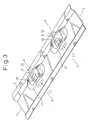
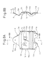
- a pair of reinforcing members 16a, 16b are integrally formed with the deformable portion 12 of the bracket 9.
- the bracket 9 together with the reinforcing members 16a and 16b is formed by a press process.
- the reinforcing members 16a and 16b are arranged on the both side edges of the deformable portion 12.
- the reinforcing member 16a is on one side of the longitudinal axis K-K of the bracket 9, and the reinforcing member 16b is on the other side of the longitudinal axis K-K.
- Each reinforcing member 16a, 16b extends from the deformable portion 12 toward the outside of the compartment 6, perpendicular to the deformable portion 12, and extends between its longitudinal ends continuously. Further, the longitudinal ends of each reinforcing member 16a, 16b are spaced apart from the adjacent end portions 10, 11 of the bracket 9.
- the inner panel 3 facing to the deformable portion 12 includes a depression 17 depressing toward the outside of the compartment 6 or outwardly.
- the deformable portion 12 and the outward depression 17 provide a clearance S between the bracket 9 and the inner panel 3.
- the depression 17 includes an opening 18 facing the distal end of the bolt 13 and the nut 14.
- the opening 18 has a dimension large enough for the bolt 13 and the nut 14 to be displaced through the opening 18, and small enough not to decrease the rigidity of the roofside rail 1.
- the bracket 9 has a thickness of 0.9 mm and the clearance S is 20 mm in the present embodiment.
- the bracket 9 may have a thickness of 0.4 to 1.2 mm, and the clearance S may be 10 to 30 mm.
- the deformable portion 12 of the bracket 9 deforms toward the outside, to thereby provide the energy absorption. Namely, first, the standing portions 12a and 12b without the reinforcing members 16a and 16b deform, mainly by buckling, and then, the standing portions 12a and 12b with the reinforcing members 16a and 16b deform, mainly by buckling. Then, the reinforcing members 16a and 16b abut the inner panel 3, and then deform mainly by bending. Finally, the intermediate portion 12c abuts the inner panel 3. In this way, energy absorption is provided.
- the distal end of the bolt 13 and the nut 14 displace through the opening 17 in the inner panel 3 and into the inner space 4 of the roofside rail 1, to thereby prevent the displacement of the bolt 13 and the nut 14 being limited by the inner panel 3.
- This enlarges the allowable displacement of the intermediate portion 12c, i.e., the clearance S.
- the deformable portion 12 protrudes toward the compartment 6 and the inner panel 3 includes the outward depression 17. This also increases the clearance S. As the clearance S becomes larger, the absorbable energy becomes larger. Thus, a large amount of energy can be absorbed in the present embodiment.
- the reinforcing members 16a and 16b deform after abutting the inner panel 3, as mentioned above. This also provides a large energy absorption.
- the reinforcing members 16a and 16b provide the deformable portion 12 with a resistance against an inward bend or twist, and enhance the tensile strength of the deformable portion 12 with respect to the inward tensile load.
- the reinforcing members 16a and 16b suppress the deformation of the deformable portion 12. Accordingly, the assist grip 7 is firmly supported by the bracket 9 in normal use.
- the bracket 9 is attached to the roofside rail 1 outside the inner space 4.
- the energy absorbing structure can be applied to the conventional roofside rail, without any modification to the roofside rail.
- Fig. 4 illustrates another embodiment of the present invention.
- a weakened portion 20 is formed in the inner panel 3 facing the bolt 3 and the nut 14.
- the weakened portion 20 comprises a plurality of slits 21 (see Fig. 5), aligned in a form of a ring with gaps therebetween.
- the gap E between the adjacent slits 21 is set to 2 mm in the present embodiment. Alternatively, the gap E may be set to a few millimeters.
- the weakened portion 20 may comprise a V-shaped groove in the form of a ring, alternatively.
- the deformable portion 12 deforms toward the outside. Then, the distal end of the bolt 13 abuts the weakened portion 20, and then breaks the weakened portion 20 to thereby form an opening in the inner panel 3, as the opening 18 in Fig. 1. After the opening is formed, the distal end of the bolt 13 and the nut 14 displace through the opening and into the inner space 4 of the roofside rail 1. Accordingly, a larger allowable displacement of the intermediate portion 12c is ensured.
- the bolt 13 abuts with the weakened portion 20, and then breaks the weakened portion 20. This provides a large energy absorption.
- the opening is not formed in the roofside rail 1 until the bolt 13 breaks the weakened portion 20.
- the rigidity of the roofside rail 1 is ensured, and it is prevented that the outside noise travels through the opening in the roofside rail into the compartment 6, as long as the weakened portion 20 is kept unbroken.
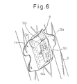
- Fig. 6 illustrates further another embodiment of the present invention.
- the reinforcing members 16a and 16b extend continuously between the standing portions 12a and 12b, respectively.
- the standing portions 12a and 12b and the reinforcing members 16a and 16b are arranged in the form of a cylinder around the intermediate portion 12c, as shown in Fig. 6.
- the bracket 9 together with the reinforcing members 16a and 16b is formed by a contraction process.
- the reinforcing members 16a and 16b connect the standing portions 12a and 12b to each other. This enhances the strength of the deformable portion 12, and suppress the inward deformation of the bracket 9 sufficiently. Accordingly, the assist grip 7 is firmly supported by the bracket 9, when the inward load acts on the assist grip 7.
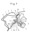
- Fig. 7 illustrates another embodiment of the present invention.
- the bracket 9 is connected to the inner panel 3 on the outer side thereof, i.e. within the inner space 4 of the roofside rail 1.
- An opening 40 is formed in the inner panel 3, through which the bolt 13 and the spacer 15 extend.
- the assist grip 7 is connected to the bracket 9.
- the inner panel 3 facing the deformable portion 12 includes a depression 41 depressed toward the compartment 6 or inwardly.
- the deformable portion 12 protrudes toward the compartment 6, and is accommodated within the inward depression 41.
- the deformable portion 12 and the inner panel 3 may contact each other, it is preferable that they are spaced apart from each other. This is because the clearance D prevents an undesirable contacting noise.
- the clearance D is set to 2 mm in the present embodiment. Alternatively, the clearance D may be set to a few millimeters.
- the assist grip 7 When an outward load larger than a predetermined load acts on the assist grip 7, first, the standing portions 12a and 12b without the reinforcing members 16a and 16b deform, mainly by buckling and, then, the standing portions 12a and 12b with the reinforcing members 16a and 16b deform, mainly by buckling. Finally, the deformable portion 12 protrudes toward the outside. In this way, energy absorption is provided.
- the spacer 15 displaces through the opening 40 in the inner panel 3, until a shoulder 15a formed in the spacer 15 abuts with the inner panel 3. Namely, the displacement of the deformable portion 12 is limited by the shoulder 15a.
- the distance S between the inner panel 3 and the shoulder 15a is an allowable displacement of the intermediate portion 12c.
- the distance S is 13 mm in the present embodiment. Alternatively, the distance S may be 10 to 30 mm.
- the reinforcing members 16a and 16b suppress the deformation of the deformable portion 12. Accordingly, the assist grip 7 is firmly supported by the bracket 9 in the normal use.
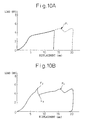
- Figs. 10A and 10B illustrate the relationships between the load and the displacement of the deformable portion 12 of the bracket 9, in the above-mentioned embodiments.
- the broken line in Fig. 10A illustrates the relationship in the embodiment shown in Fig. 1, and the solid line in Fig. 10A illustrates the relationship in the embodiment shown in Fig. 7.
- Fig. 10B illustrates the relationship in the embodiment shown in Fig. 4.
- the load increases as the displacement increases, and the peak value is obtained as shown by an arrow F1.
- the load increases as the displacement increases, and the peak value is obtained as shown by an arrow F2.
- the peak value is obtained as shown by an arrow F2.
- the load increases again, as shown by an arrow F3.
- the peak value is obtained as shown by an arrow F4.
- the area enclosed by the curve and the X-axis in Figs. 10A and 10B represents the absorbed energy.
- the load must be kept lower, and thus the allowable displacement or the initial slope of the curve of the load-displacement relationships is required to be large to increase the absorbable energy.
- the allowable displacement is made larger by the inwardly protruding bracket 9. Further, in the embodiments shown in Figs. 1 and 4, the depression 17 in the inner panel 3 enlarges the allowable displacement. On the other hand, the bracket 9 of metal makes the initial slope of the curve larger. Further, the reinforcing members 16a and 16b, especially those shown in Fig. 6, also make the initial slope of the curve larger. Accordingly, an increased absorbable energy is obtained according to the present invention.
- reinforcing members 16a and 16b which extend from the bracket toward the outside of the compartment 6.
- reinforcing members 16a and 16b which extend from the bracket toward the compartment 6, or toward both sides may be provided.
- an energy absorbing structure for an automobile capable of supporting the assist grip firmly, while providing energy absorption for an outward load on the assist grip.
Landscapes
- Engineering & Computer Science (AREA)
- Mechanical Engineering (AREA)
- Transportation (AREA)
- Passenger Equipment (AREA)
- Body Structure For Vehicles (AREA)
- Vehicle Interior And Exterior Ornaments, Soundproofing, And Insulation (AREA)
Claims (21)
- Une structure absorbant l'énergie pour une automobile, ayant un habitacle (6), un rail côté plafond (1), avec une section fermée et un espace intérieur (4), le rail côté plafond (1) ayant une face (3) tournée vers l'habitacle (6), et une prise d'assistance (7) reliée au côté habitacle du rail côté plafond (1), la structure absorbant l'énergie comprenant:caractérisée en ce queun support (9) interposable entre le rail côté plafond (1) et la prise d'assistance (7), le support (9) ayant des parties d'extrémités (10, 11) longitudinales susceptible d'être fixées sur le rail côté plafond (1), et une partie déformable (12) s'étendant entre les parties d'extrémités (10, 11), auxquelles la prise d'assistance (7) est susceptible d'être reliée, la partie déformable (12) se déformant en direction de l'extérieur de l'habitacle (6) pour effectuer l'absorption d'énergie lorsqu'une charge extéricure, supérieure à une charge prédéterminée, agit sur la prise d'assistance (7);au moins un organe de renforcement (16a, 16b),
le au moins un organe de renforcement (16a, 16b) est formé d'une seule pièce avec la partie déformable (12) du support (9), s'étend le long de l'axe longitudinal du support (9) et a une extrémité libre faisant saillie de la partie déformable (12). - Une structure d'absorption de l'énergie selon la revendication 1,
caractérisée en ce que
le au moins un organe de renforcement (16a, 16b) résiste à ou supprime une déformation intérieure du support (9). - Une structure d'absorption de l'énergie selon la revendication 1 ou 2, dans laquelle une paire d'organes de renforcement (16a, 16b) sont formés avec la partie déformable (12) du support (9), l'une étant agencée sur un côté de l'axe longitudinal (K - K) du support (9) et l'autre étant agencé sur l'autre côté de l'axe longitudinal (K - K) du support (9).
- Une structure d'absorptions de l'énergie selon la revendication 3, dans laquelle les organes de renforcement (16a, 16b) sont agencés sur les deux bords latéraux de la partie déformable (12) du support (9).
- Une structure d'absorption de l'énergie selon la revendication 1 ou 2, dans laquelle l'organe de renforcement (16a, 16b) s'étend de façon continue entre ses extrémités longitudinales, et dans laquelle les extrémités longitudinales de l'organe de renforcement sont espacées des parties d'extrémité (10, 11) adjacentes du support (9), respectivement.
- Une structure d'absorption de l'énergie selon la revendication 1 ou 2, dans laquelle l'organe de renforcement (16a, 16b) s'étend depuis la partie déformable (12) du support, en direction de l'extérieur de l'habitacle (6).
- Une structure d'absorption de l'énergie selon la revendication 1 ou 2, dans laquelle la partie déformable (12) du support (9) fait saillie vers l'habitacle (6).
- Une structure d'absorption de l'énergie selon la revendication 7, dans laquelle la partie déformable (12) du support (9) comprend des parties montantes (12a, 12b) s'étendant depuis les parties d'extrémité (10, 11) du support (9), en direction de l'habitacle (6) et une partie intermédiaire (12c) s'étendant entre les parties montantes (12a, 12b) dans laquelle la prise d'assistance (7) est reliée à la partie intermédiaire (12c).
- Une structure d'absorption de l'énergie selon la revendication 8, dans laquelle la partie intermédiaire (12c) du support (9) et une partie (3) du rail côté plafond (1) tournée vers le support (9) sont sensiblement parallèle entre elles.
- Une structure d'absorption de l'énergie selon la revendication 8, dans laquelle une paire d'organes de renforcement (16a, 16b) sont formés avec le support (9) et s'étendent entre les parties montantes (12a, 12b) du support (9), de manière que les parties montantes (12a, 12b) et les organes de renforcement (16a, 16b) soient agencés à la forme d'un cylindre autour de la partie intermédiaire (12c) du support (9).
- Une structure d'absorption de l'énergie selon la revendication 1 ou 2, dans laquelle le support (9) est relié au côté habitacle du rail côté plafond (1).
- Une structure d'absorption de l'énergie selon la revendication 11, dans laquelle une fixation (13, 14) pour connecter la prise d'assistance (7) au support (9) s'étend depuis la prise d'assistance (7) par l'intermédiaire du support (9) vers le rail côté plafond (1), et dans lequel le rail côté plafond (1) comprend une ouverture (18) tournée vers la fixation (13, 14) de manière que, lorsque le support (9) se déforme en direction de l'extérieur de l'habitacle (6), la fixation (13, 14) se déplace à travers l'ouverture (18).
- Une structure d'absorption de l'énergie selon la revendication 11, dans laquelle une fixation (13, 14) devant connecter la prise d'assistance (7) au support (9) s'étend depuis la prise d'assistance (7) par l'intermédiaire du support (9) vers le rail côté plafond (1) et dans lequel le rail côté plafond (1) comprend une partie affaiblie (20) tournée vers la fixation (13, 14), de manière que lorsque le support (9) se déforme vers l'extérieur de l'habitacle (6), la fixation (13,14) rompe la partie affaiblie (20) pour former une ouverture sur le rail côté plafond (1) et est déplacée à travers l'ouverture.
- Une structure d'absorption de l'énergie selon la revendication 11, dans laquelle le rail côté plafond (1) comprend un creusement extérieur (17) tourné vers le support (9).
- Une structure d'absorption de l'énergie selon la revendication 1 ou 2, dans laquelle le support (9) est connecté au rail côté plafond (1) à l'intérieur de son espace intérieur (4).
- Une structure d'absorption de l'énergie selon la revendication 15, dans laquelle le rail côté plafond (1) comprend un creusement intérieur (41), tourné vers le support (9).
- Une structure d'absorption de l'énergie selon la revendication 1 ou 2, dans laquelle la partie déformable (12) du support (9) est espacée du rail côté plafond (1).
- Une structure d'absorption de l'énergie selon la revendication 1 ou 2, dans laquelle l'axe longitudinal (K - K) du support (9) est sensiblement perpendiculaire à l'axe longitudinal (J - J) du rail côté plafond (1).
- Une structure d'absorption de l'énergie selon la revendication 1 ou 2, dans laquelle une fixation (13, 14) devant connecter la prise d'assistance (7) au support (9) est sensiblement perpendiculaire à la partie déformable (12) du support (9).
- Une structure d'absorption de l'énergie selon la revendication 1 ou 2, dans laquelle le support (9) est formé d'une plaque métallique.
- Une structure d'absorption de l'énergie selon la revendication 1 ou 2, dans laquelle le rail côté plafond (1) comprend une moitié extérieure (2) et une moitié intérieure (3) connectées l'une à l'autre, la moitié intérieure (3) étant agencée dans l'habitacle (6), et dans laquelle le support (9) est connecté à la moitié intérieure (3).
Applications Claiming Priority (3)
| Application Number | Priority Date | Filing Date | Title |
|---|---|---|---|
| JP355457/96 | 1996-12-24 | ||
| JP35545796 | 1996-12-24 | ||
| JP08355457A JP3085227B2 (ja) | 1996-12-24 | 1996-12-24 | 自動車の車体上部のエネルギ吸収構造 |
Publications (2)
| Publication Number | Publication Date |
|---|---|
| EP0852191A1 EP0852191A1 (fr) | 1998-07-08 |
| EP0852191B1 true EP0852191B1 (fr) | 2003-03-26 |
Family
ID=18444069
Family Applications (1)
| Application Number | Title | Priority Date | Filing Date |
|---|---|---|---|
| EP97122783A Expired - Lifetime EP0852191B1 (fr) | 1996-12-24 | 1997-12-23 | Structure d'absorbtion d'énergie pour véhicule |
Country Status (4)
| Country | Link |
|---|---|
| US (1) | US6126230A (fr) |
| EP (1) | EP0852191B1 (fr) |
| JP (1) | JP3085227B2 (fr) |
| DE (1) | DE69720171T2 (fr) |
Cited By (1)
| Publication number | Priority date | Publication date | Assignee | Title |
|---|---|---|---|---|
| US7407209B2 (en) | 2006-02-27 | 2008-08-05 | Nissan Technical Center North America, Inc. | Vehicle grab handle |
Families Citing this family (33)
| Publication number | Priority date | Publication date | Assignee | Title |
|---|---|---|---|---|
| JPH0639557U (ja) * | 1992-11-06 | 1994-05-27 | 株式会社三ツ葉電機製作所 | 螺旋軸式移動装置のナツトユニツト構造 |
| GB9809248D0 (en) * | 1998-05-01 | 1998-07-01 | Rover Group | An absorption arrangement |
| WO2000026058A1 (fr) * | 1998-10-30 | 2000-05-11 | Volkswagen Aktiengesellschaft | Support pour accessoire faisant saillie dans l'habitacle d'une automobile, notamment support de poignee |
| US6647594B1 (en) * | 1999-12-14 | 2003-11-18 | Ford Global Technologies, Llc | Grab handle assembly |
| DE10007361A1 (de) * | 2000-02-18 | 2001-08-23 | Volkswagen Ag | Adapter für einen Dachhaltegriff eines Kfz |
| GB2368821B (en) * | 2000-11-14 | 2003-12-31 | Ford Global Tech Inc | A handle assembly |
| DE10140338B4 (de) * | 2001-08-16 | 2011-09-29 | Volkswagen Ag | Adapter zur Anbringung eines Haltegriffs |
| JP3861651B2 (ja) * | 2001-10-12 | 2006-12-20 | 三菱自動車エンジニアリング株式会社 | 車両のショルダアンカ取付部の補強構造 |
| US6685257B1 (en) | 2002-04-18 | 2004-02-03 | Johnson Controls Technology Company | Extrusion for the siderail of a vehicle to provide head impact countermeasure and support for siderail components |
| US6929286B2 (en) | 2002-08-26 | 2005-08-16 | Autoliv Asp, Inc. | Energy absorbing turning loop cover |
| JP4144362B2 (ja) * | 2003-01-20 | 2008-09-03 | スズキ株式会社 | ブラケット取付構造 |
| AU2004200724B2 (en) * | 2003-02-25 | 2008-08-28 | Peter Michael Fitzgerald | Energy absorbing device |
| KR100610190B1 (ko) * | 2004-06-23 | 2006-08-10 | 기아자동차주식회사 | 3점식 시트벨트의 장착구조 |
| DE102005050259A1 (de) * | 2005-10-20 | 2007-04-26 | GM Global Technology Operations, Inc., Detroit | Halter für den Haltegriff in einem Kraftfahrzeug |
| KR100757152B1 (ko) | 2005-12-09 | 2007-09-07 | 현대자동차주식회사 | 차량용 루프 어시스트 핸들 브라켓트 장치 |
| US7290831B2 (en) * | 2006-04-06 | 2007-11-06 | Gm Global Technology Operations, Inc. | Vehicle with layered roof build |
| KR100787673B1 (ko) | 2006-09-13 | 2007-12-21 | 기아자동차주식회사 | 자동차의 충격흡수용 어시스트 핸들 마운팅 브라켓 구조 |
| DE102006053781B4 (de) * | 2006-11-15 | 2010-07-08 | Dr. Ing. H.C. F. Porsche Aktiengesellschaft | Adaptervorrichtung für einen Haltegriff |
| DE102007042277B4 (de) * | 2007-09-06 | 2010-07-08 | Thyssenkrupp Drauz Nothelfer Gmbh | Dachkonstruktion einer Fahrzeugkarosserie |
| DE102007043116A1 (de) | 2007-09-10 | 2009-03-12 | GM Global Technology Operations, Inc., Detroit | Halteblechanordnung für den Haltegriff in einem Kraftfahrzeug |
| US7896417B2 (en) | 2009-07-31 | 2011-03-01 | Honda Motor Co., Ltd. | Grab handle bracket |
| DE102009048338A1 (de) * | 2009-10-06 | 2011-04-21 | GM Global Technology Operations, Inc., Detroit | Befestigungseinrichtung eines Haltegriffs an einem in Fahrtrichtung verlaufenden Dachholm eines Kraftfahrzeuges |
| FR2960494B1 (fr) * | 2010-05-28 | 2013-03-08 | Peugeot Citroen Automobiles Sa | Dispositif de fixation d'une poignee interieure de maintien a un arc de pavillon et vehicule automobile equipe de poignees fixees au moyen d'un tel dispositif. |
| JP5608749B2 (ja) * | 2010-07-23 | 2014-10-15 | 本田技研工業株式会社 | 車両の内装部品の配設構造 |
| KR101210086B1 (ko) * | 2010-11-12 | 2012-12-07 | 현대자동차주식회사 | 아우터 어퍼센터필러 레인포스와 시트벨트 브래킷의 결합구조 |
| DE102010052454B4 (de) * | 2010-11-24 | 2014-12-11 | GM Global Technology Operations LLC (n. d. Ges. d. Staates Delaware) | Halteteil für den Haltegriff in einem Kraftfahrzeug und Haltegriffanordnung in einem Kraftfahrzeug |
| JP5899937B2 (ja) * | 2012-01-12 | 2016-04-06 | トヨタ自動車株式会社 | 自動車用ドアトリムの取付構造 |
| DE102012006515A1 (de) * | 2012-03-29 | 2013-10-02 | GM Global Technology Operations LLC (n. d. Gesetzen des Staates Delaware) | Haltevorrichtung für einen Haltegriff in einem Kraftfahrzeug und Kraftfahrzeug mit einer solchen Haltevorrichtung und einem Haltegriff |
| JP5703275B2 (ja) | 2012-10-31 | 2015-04-15 | 株式会社豊田自動織機 | アシストグリップの取付構造 |
| US9409463B2 (en) | 2014-12-10 | 2016-08-09 | Honda Motor Co., Ltd. | Vehicle structural member and bracket |
| CN110979129A (zh) * | 2020-01-05 | 2020-04-10 | 江苏开沃汽车有限公司 | 一种乘用车乘客扶手支架安装结构及其安装方法 |
| US11332082B1 (en) | 2020-12-07 | 2022-05-17 | Ford Global Technologies, Llc | Vehicle trim panel assembly |
| CN112706674A (zh) * | 2021-01-29 | 2021-04-27 | 蔚来汽车科技(安徽)有限公司 | 一种汽车顶棚拉手安装支架结构和汽车 |
Family Cites Families (19)
| Publication number | Priority date | Publication date | Assignee | Title |
|---|---|---|---|---|
| US2939741A (en) * | 1956-10-25 | 1960-06-07 | Gen Motors Corp | Sunshade support assembly |
| US5169204A (en) * | 1992-04-08 | 1992-12-08 | Davidson Textron Inc. | Energy absorbing inner door panel with fasteners to absorb body impact energy |
| JP3399592B2 (ja) | 1993-08-26 | 2003-04-21 | マツダ株式会社 | 自動車の上部構造 |
| JPH0796790A (ja) * | 1993-09-27 | 1995-04-11 | Toyoda Gosei Co Ltd | アシストグリップ |
| US5529344A (en) | 1993-11-30 | 1996-06-25 | Toyota Jidosha Kabushiki Kaisha | Seat belt device for automobile |
| JP2785669B2 (ja) * | 1993-12-21 | 1998-08-13 | トヨタ自動車株式会社 | 自動車用シートベルト装置 |
| JPH07172169A (ja) * | 1993-12-20 | 1995-07-11 | Toyota Motor Corp | 自動車のサンバイザの取付け構造 |
| JPH07232583A (ja) | 1994-02-25 | 1995-09-05 | Toyota Motor Corp | アシストグリップの取付け構造 |
| JP3319145B2 (ja) * | 1994-04-28 | 2002-08-26 | 日産自動車株式会社 | 車両用サンバイザー取付構造 |
| JPH07304419A (ja) * | 1994-05-10 | 1995-11-21 | Nissan Motor Co Ltd | 車両用シートベルトアンカー取付構造 |
| JPH07329623A (ja) * | 1994-06-08 | 1995-12-19 | Toyoda Gosei Co Ltd | アシストグリップ |
| JPH0820274A (ja) * | 1994-07-08 | 1996-01-23 | Toyota Motor Corp | アシストグリップの取付け構造 |
| US5519917A (en) * | 1994-08-05 | 1996-05-28 | Cambridge Industries, Inc. | Mounting device for a front mounted removable handle and the like |
| JPH08113162A (ja) * | 1994-10-19 | 1996-05-07 | Toyota Motor Corp | 自動車の車体上部の乗員の保護構造及び保護構造の製造方法 |
| CA2207870A1 (fr) * | 1994-12-02 | 1996-06-06 | Edward R. Adams | Dispositif de fixation |
| JP3279115B2 (ja) * | 1995-02-28 | 2002-04-30 | 日産自動車株式会社 | 自動車用ピラーガーニッシュ支持構造 |
| DE19611724C2 (de) * | 1996-03-25 | 2001-04-05 | United Carr Gmbh Trw | Haltegriff aus Kunststoff |
| JP3362598B2 (ja) * | 1996-04-12 | 2003-01-07 | トヨタ自動車株式会社 | 自動車の車体上部のエネルギ吸収構造 |
| US5855408A (en) * | 1997-05-09 | 1999-01-05 | Lear Corporation | Ingress and egress handle assembly |
-
1996
- 1996-12-24 JP JP08355457A patent/JP3085227B2/ja not_active Expired - Lifetime
-
1997
- 1997-12-23 DE DE69720171T patent/DE69720171T2/de not_active Expired - Lifetime
- 1997-12-23 EP EP97122783A patent/EP0852191B1/fr not_active Expired - Lifetime
- 1997-12-24 US US08/998,284 patent/US6126230A/en not_active Expired - Lifetime
Cited By (1)
| Publication number | Priority date | Publication date | Assignee | Title |
|---|---|---|---|---|
| US7407209B2 (en) | 2006-02-27 | 2008-08-05 | Nissan Technical Center North America, Inc. | Vehicle grab handle |
Also Published As
| Publication number | Publication date |
|---|---|
| US6126230A (en) | 2000-10-03 |
| JP3085227B2 (ja) | 2000-09-04 |
| EP0852191A1 (fr) | 1998-07-08 |
| DE69720171D1 (de) | 2003-04-30 |
| DE69720171T2 (de) | 2003-10-23 |
| JPH10181490A (ja) | 1998-07-07 |
Similar Documents
| Publication | Publication Date | Title |
|---|---|---|
| EP0852191B1 (fr) | Structure d'absorbtion d'énergie pour véhicule | |
| US5813718A (en) | Guard beam for automotive door structure | |
| US5992922A (en) | Side impact protection member for motor vehicle doors | |
| US5560672A (en) | Energy absorbing beam | |
| US7631924B2 (en) | Crash box for a vehicle | |
| US6409257B1 (en) | Vehicle side sill structure | |
| EP1329375B1 (fr) | Structure de connection supérieure de montant de véhicule automobile | |
| US6354654B2 (en) | Vehicle frame reinforcement | |
| US6676200B1 (en) | Automotive underbody with lateral energy absorption augmentation | |
| KR100352324B1 (ko) | 숄더앵커 구조 | |
| US5039160A (en) | Side-collision protective beam for motor vehicle | |
| US5046777A (en) | Impact girder in an automobile wall assembly with intentional buckling of edge portions | |
| US4909567A (en) | Vehicle body construction | |
| JP3796834B2 (ja) | サイドメンバ補強構造 | |
| JP3109427B2 (ja) | 自動車の車体上部構造 | |
| JP3308719B2 (ja) | バンパーリインフォースメント | |
| US5452545A (en) | Impact support for a door of a motor vehicle | |
| JPH01249571A (ja) | 衝撃エネルギー吸収チルト式ステアリングコラム | |
| KR0165191B1 (ko) | 도어 임팩트 빔 | |
| JP2002012108A (ja) | 衝撃吸収部材及びこれを用いたバンパステイ | |
| KR200188439Y1 (ko) | 자동차용 도어 | |
| KR100268991B1 (ko) | 자동차 센터필라의 상부 보강구조 | |
| JPH0725239A (ja) | 自動車のドア用インパクトビーム | |
| KR100222537B1 (ko) | 자동차용 도어 | |
| KR0128313Y1 (ko) | 자동차의 사이드 실 멤버 보강구조 |
Legal Events
| Date | Code | Title | Description |
|---|---|---|---|
| PUAI | Public reference made under article 153(3) epc to a published international application that has entered the european phase |
Free format text: ORIGINAL CODE: 0009012 |
|
| 17P | Request for examination filed |
Effective date: 19971223 |
|
| AK | Designated contracting states |
Kind code of ref document: A1 Designated state(s): DE FR GB |
|
| AX | Request for extension of the european patent |
Free format text: AL;LT;LV;MK;RO;SI |
|
| AKX | Designation fees paid |
Free format text: DE FR GB |
|
| RBV | Designated contracting states (corrected) |
Designated state(s): DE FR GB |
|
| 17Q | First examination report despatched |
Effective date: 20010830 |
|
| GRAH | Despatch of communication of intention to grant a patent |
Free format text: ORIGINAL CODE: EPIDOS IGRA |
|
| GRAH | Despatch of communication of intention to grant a patent |
Free format text: ORIGINAL CODE: EPIDOS IGRA |
|
| GRAA | (expected) grant |
Free format text: ORIGINAL CODE: 0009210 |
|
| AK | Designated contracting states |
Designated state(s): DE FR GB |
|
| REG | Reference to a national code |
Ref country code: GB Ref legal event code: FG4D |
|
| REF | Corresponds to: |
Ref document number: 69720171 Country of ref document: DE Date of ref document: 20030430 Kind code of ref document: P |
|
| ET | Fr: translation filed | ||
| PLBE | No opposition filed within time limit |
Free format text: ORIGINAL CODE: 0009261 |
|
| STAA | Information on the status of an ep patent application or granted ep patent |
Free format text: STATUS: NO OPPOSITION FILED WITHIN TIME LIMIT |
|
| 26N | No opposition filed |
Effective date: 20031230 |
|
| REG | Reference to a national code |
Ref country code: GB Ref legal event code: 746 Effective date: 20060103 |
|
| REG | Reference to a national code |
Ref country code: FR Ref legal event code: PLFP Year of fee payment: 19 |
|
| REG | Reference to a national code |
Ref country code: FR Ref legal event code: PLFP Year of fee payment: 20 |
|
| PGFP | Annual fee paid to national office [announced via postgrant information from national office to epo] |
Ref country code: DE Payment date: 20161220 Year of fee payment: 20 Ref country code: GB Payment date: 20161221 Year of fee payment: 20 Ref country code: FR Payment date: 20161111 Year of fee payment: 20 |
|
| REG | Reference to a national code |
Ref country code: DE Ref legal event code: R071 Ref document number: 69720171 Country of ref document: DE |
|
| REG | Reference to a national code |
Ref country code: GB Ref legal event code: PE20 Expiry date: 20171222 |
|
| PG25 | Lapsed in a contracting state [announced via postgrant information from national office to epo] |
Ref country code: GB Free format text: LAPSE BECAUSE OF EXPIRATION OF PROTECTION Effective date: 20171222 |