EP0493774B1 - Porte pour cabine de véhicule - Google Patents
Porte pour cabine de véhicule Download PDFInfo
- Publication number
- EP0493774B1 EP0493774B1 EP91122081A EP91122081A EP0493774B1 EP 0493774 B1 EP0493774 B1 EP 0493774B1 EP 91122081 A EP91122081 A EP 91122081A EP 91122081 A EP91122081 A EP 91122081A EP 0493774 B1 EP0493774 B1 EP 0493774B1
- Authority
- EP
- European Patent Office
- Prior art keywords
- door
- frame
- cab
- cabin
- door frame
- Prior art date
- Legal status (The legal status is an assumption and is not a legal conclusion. Google has not performed a legal analysis and makes no representation as to the accuracy of the status listed.)
- Expired - Lifetime
Links
- 239000004033 plastic Substances 0.000 claims abstract description 24
- 229920003023 plastic Polymers 0.000 claims abstract description 24
- 238000005266 casting Methods 0.000 claims abstract description 6
- 239000000463 material Substances 0.000 claims description 6
- 229920000642 polymer Polymers 0.000 claims description 6
- 229920002635 polyurethane Polymers 0.000 claims description 4
- 239000004814 polyurethane Substances 0.000 claims description 4
- 239000002184 metal Substances 0.000 claims 1
- 229910000831 Steel Inorganic materials 0.000 description 7
- 239000010959 steel Substances 0.000 description 7
- 238000010276 construction Methods 0.000 description 4
- 230000005540 biological transmission Effects 0.000 description 3
- 239000011230 binding agent Substances 0.000 description 2
- 238000002485 combustion reaction Methods 0.000 description 2
- 230000006378 damage Effects 0.000 description 2
- 239000011521 glass Substances 0.000 description 2
- JEIPFZHSYJVQDO-UHFFFAOYSA-N iron(III) oxide Inorganic materials O=[Fe]O[Fe]=O JEIPFZHSYJVQDO-UHFFFAOYSA-N 0.000 description 2
- 238000004519 manufacturing process Methods 0.000 description 2
- 239000003973 paint Substances 0.000 description 2
- 238000009423 ventilation Methods 0.000 description 2
- 208000027418 Wounds and injury Diseases 0.000 description 1
- HCHKCACWOHOZIP-UHFFFAOYSA-N Zinc Chemical compound [Zn] HCHKCACWOHOZIP-UHFFFAOYSA-N 0.000 description 1
- 230000006978 adaptation Effects 0.000 description 1
- 238000006243 chemical reaction Methods 0.000 description 1
- 239000011248 coating agent Substances 0.000 description 1
- 238000000576 coating method Methods 0.000 description 1
- 238000002347 injection Methods 0.000 description 1
- 239000007924 injection Substances 0.000 description 1
- 208000014674 injury Diseases 0.000 description 1
- 239000012948 isocyanate Substances 0.000 description 1
- 150000002513 isocyanates Chemical class 0.000 description 1
- 238000000034 method Methods 0.000 description 1
- 239000006223 plastic coating Substances 0.000 description 1
- 229920005862 polyol Polymers 0.000 description 1
- 150000003077 polyols Chemical class 0.000 description 1
- 239000011347 resin Substances 0.000 description 1
- 229920005989 resin Polymers 0.000 description 1
- 230000003678 scratch resistant effect Effects 0.000 description 1
- 230000035939 shock Effects 0.000 description 1
- 238000005507 spraying Methods 0.000 description 1
- 230000000087 stabilizing effect Effects 0.000 description 1
- 239000011701 zinc Substances 0.000 description 1
- 229910052725 zinc Inorganic materials 0.000 description 1
Images



Classifications
-
- B—PERFORMING OPERATIONS; TRANSPORTING
- B60—VEHICLES IN GENERAL
- B60J—WINDOWS, WINDSCREENS, NON-FIXED ROOFS, DOORS, OR SIMILAR DEVICES FOR VEHICLES; REMOVABLE EXTERNAL PROTECTIVE COVERINGS SPECIALLY ADAPTED FOR VEHICLES
- B60J5/00—Doors
- B60J5/04—Doors arranged at the vehicle sides
- B60J5/0486—Special type
- B60J5/0487—Special type simplified doors related to cabins of, e.g. golf carts, tractors, jeeps, cranes, forklifts, etc.
Definitions
- the invention relates to a cabin door for a vehicle cabin, which has frame parts which at least partially define a door opening with a vertically running element on one side of the door opening and an upper horizontally running element above the door opening, the cabin door having a metallic and essentially after has inside open outer door frame with a substantially vertically extending first and second side part and is hinged to the frame parts of the vehicle cabin hinged.
- Vehicle cabins of this type are used in agricultural tractors and in vehicles which are used in the construction industry, such as in backhoe loaders. Modern vehicle cabins are designed to give the operator an all-round view, and up to 55% of the window areas can be opened for good ventilation, which is particularly important for stationary use in the construction industry. This is also the case with the vehicle cabin to which the cabin door described in document US-A-3 802 530 belongs.
- the cabin door extends into the area of the windshield, which can be partially opened if only one door is present. If there is a right and left door, the windshield can be opened completely. Such cabin doors are curved and not easy to manufacture.
- the steel frame is welded and for an attractive appearance, but also to avoid sharp edges and thus the risk of injury to the operating personnel, the weld seams have to be machined before the cabin door can be sprayed. With the rough use of such vehicles, at least scratches will soon appear in the paint.
- the large window parts are attached to the door frame.
- the object to be achieved with the invention is seen in to design such cabin doors more advantageously.
- This object is achieved according to the invention in that the door frame is surrounded by casting by a plastic that forms large internal window openings, this plastic jacket has contact surfaces with which the transparent window means are connected.
- the second side part of the door frame is provided with a door lock, the forces emanating from there are also introduced directly into the steel frame of the cabin door.
- a permanent covering for the cabin door can be achieved in that the plastic is a polymer and is cast around the door frame.
- the polymer is expediently a polyurethane.
- a particularly good protection for the window panes of the cabin door can be achieved according to a further proposal of the invention in that the plastic surrounding the door frame is shaped in the region of its window openings in such a way that it surrounds the window means from the outside.
- the window means are glued to the plastic.
- the invention is used primarily on a backhoe loader shown in FIG. 1, which has a vehicle frame 10 with rear drivable wheels 14 and steerable wheels 16 and 18 on the front.
- vehicle frame 10 with rear drivable wheels 14 and steerable wheels 16 and 18 on the front.
- such vehicles have an internal combustion engine, which is provided on the front of the vehicle frame and is not shown in the drawing and is covered by an engine cover 20.
- a transmission is provided behind the internal combustion engine, the rearward-extending output shaft of which drives the rear wheels 14 via a differential and rear drive axles.
- the differential and the housing for the drive axles are part of the vehicle frame 10.
- a control console 22 is essentially U-shaped and is provided directly behind the engine cover 20. It receives a steering wheel, also not shown, in the longitudinal center plane of the vehicle, in which the engine output shaft and the transmission output shaft are also located.
- Such conventional backhoe loaders have a loader device 28 provided on the front and an excavator device 30 also connected to the rear of the vehicle frame 10.
- an excavator device 30 When working with the excavator device 30, the vehicle is jacked up via stabilizing struts 32 at the rear end of the vehicle frame 10.
- a control station On the vehicle frame 10 between the right and left rear wheels 14 and behind the control console 22 is a control station with a horizontally running floor and a 180 ° pivotable seat arranged thereon in the longitudinal center plane, which when working with the loading device 28 or when driving Machine is facing forward. In this sitting position, pedals for actuating a clutch or the brakes and shift levers for the transmission are easily accessible.
- the seat When working with the excavator device 30, the seat is pivoted backwards by 180 °, so that the operator can easily operate the excavator device using suitable control levers.
- the operating station is located within a vehicle cabin 42, the cabin frame of which is designed as a rollover protection for the operator.
- the cabin frame has front substantially vertical right and left posts 44 and 46 and rear also substantially vertical posts 50, of which only the left one can be seen in the drawing.
- the posts carry a canopy 52 at their upper ends and are attached to the vehicle frame 10 at their lower ends.
- these connection points are not shown in the drawing.
- the vehicle cabin 42 has right and left side parts 54 which, apart from the fact that they are mirror images of one another, are of identical design. Only the left side part can be seen in the drawing. Every side part 54 has a wheel cover 56 which protrudes sideways outwards and in each case partially covers a rear wheel 14.
- the part of the side parts 54 lying above the wheel cover 56 consists of two substantially vertically directed disc parts 58.
- the front posts 44 and 46 are arranged in their upper region in an inclined manner inwards and backwards, while the upper regions of the rear posts 50 are bent inwards and forwards so that the walls of the cabin taper upwards.
- the two pane parts 58 on each side can be opened to improve the ventilation of the cabin.
- the vehicle cabin 42 is also glazed on its rear side. These panes can also be opened completely or partially.
- the front 62 of the cabin is also almost completely glazed, so that the vehicle cabin ensures excellent all-round visibility.
- the front side 62 is provided with an inverted U-shaped frame part 64 which engages over the correspondingly designed control console 22.
- a vertically extending strut 66 in the front side 62 extends from the frame part 64 upwards to the cabin roof 52 and is offset to the left with respect to the longitudinal median plane in order not to impair the operator's view to the front.
- the strut 66 and the left edge of the frame part 64 form the right side of a door opening 68, which is closed at the top by the cabin roof 52.
- the door opening is delimited by the floor of the control station, whereas the left side of the door opening 68 is formed by the upper part of the left front post 46 and the part of the left wheel cover 56 which slopes downwards and forwards.
- a left cabin door 70 is fitted, which, with the exception of its outer door frame, is almost completely glazed and essentially consists of an upper glass insert 72 and a lower glass insert 74.
- the cabin door 70 is hinged to two vertically spaced hinges 76 and can pivot about its right side into an open position.
- the upper hinge 76 is connected to the underside of the cabin roof 52 in the region of the upper end of the strut 66 and the lower hinge 76 engages the frame part 64.
- a lock 78 is also provided on the left side of the cabin door 70 and is used to selectively lock the door with the left front post 46.
- a right door opening 84 in the right side panel is also delimited by the strut 66, the canopy 52, the right front pillar 44, the right front edge of the right wheel cover, the bottom of the control stand and the right edge of the frame part 64.
- a right door 86 is fitted into this door opening 84 in such a way that it can pivot between its closed position shown in FIG. 1 by two hinges 108 and 110 into its open position, the hinges 108 and 110 having the right front post 44 on the right side of the door connect. Since the strut 66 is offset to the left, but the driver's cabin 42 is centered with respect to the longitudinal median plane, the right cabin door is considerably wider than the left cabin door 70.
- the right cabin door 86 also essentially consists of an upper and a lower window means 88, 89 in the form of disc parts.
- the entire front side 62 is curved, the concave side facing the driver's seat.
- the upper window means 72 and 88 of the two cabin doors form a curved windshield, which then also opens when the door is opened.
- the curved design of the front improves the appearance of the cabin and, above all, enlarges the interior.
- the special design of the doors enlarged getting in and out.
- a loading space 80 with a step 82 below it is provided slightly below the floor of the control station, which facilitates entry and exit into the cabin. Similar arrangements are provided on the right side of the cabin for the same purpose.
- the construction of the right and left car doors is essentially the same, except that the right car door 86 is considerably wider. Therefore, only the construction of the right cabin door 86 is discussed in detail below.
- the manufacturing process for the right and left cabin doors is identical.
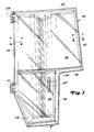
- the right cabin door has a door frame 90 made of steel.
- this consists of a right side part 92, which extends over the entire length of the door, an upper left side part 93 and a lower left side part 94.
- An upper part 95 connects the upper ends of the right and left side parts 92 and 93
- a horizontal middle part 96 extends between a middle region of the right side part 92 and the lower end of the upper left side part 93 and a bottom part 97 finally connects the lower end of the right side part 92 to the lower end of the left lower side part 94.
- the upper end of the lower left side part 94 is connected to a central region of the central part 96.
- the lower end of the right side part is formed obliquely inwards and the horizontally running parts 95 and 96 are bent, the concave side of which is directed backwards. Except for the middle part 96, the door frame parts form the outer periphery of the door frame 90.
- the central part 96 divides the cabin door 86 into an upper and a lower part, the narrower lower part being offset from the upper part for adaptation to the control console 22.
- the upper left side part 93 lies in the closed position of the right cabin door 86 directly next to the strut 66.
- a fastening part 98 for receiving a windshield wiper is connected to the upper part 95 and extends downwards from this, while a fastening part 99 for a locking device is connected to the upper end of the lower left side part 94.
- Corresponding fastening means and fastening bores are provided in the fastening parts and hinge brackets 100, 102 for receiving a windshield wiper system, a door lock 107 and upper and lower hinges 108 and 110.
- Each door frame is covered with a jacket 104 made of polyurethane, which is applied to the door frame by casting.
- the shape of the plastic casing can correspond to that of the door frames with the exception of a lower part 106 which surrounds the lower part of, for example, the door frame 90 and is bulged outwards.
- the casting process is a reaction injection process using a polyol zinc resin and an isocyanate material which are simultaneously introduced into the casting mold, in which they react and form the finished polymer, in the present case the polyurethane.
- the window means 88 and 89 are connected to the plastic jacket 104 using a conventional binder 112.
- the plastic jacket expediently has a shape which surrounds the panes like a frame and has contact surfaces to which the binder can be applied.
- the windshield wiper device, the locking mechanism and the hinges are connected directly to the metallic door frame via appropriate fastening means.
- a door seal 114 which can be hollow in cross-section and made of flexible material, is still connected to the inner periphery of the door frame 90 and, when the cabin door is closed, bears against the corresponding frame parts of the door opening.
- the plastic coating allows a clean exterior and covers weld seams and sharp edges of the door frame. An attractive appearance is created.
- the plastic does not rust and can absorb minor impacts without damage.
- the steel frame sufficiently stabilizes the cabin door, forces exerted by the hinges or the locking device being introduced directly into the metallic door frame.
- the steel frame also ensures that the cabin door does not warp in the course of its use, so that it always remains well sealed even after a long period of use.
Landscapes
- Engineering & Computer Science (AREA)
- Mechanical Engineering (AREA)
- Body Structure For Vehicles (AREA)
- Harvester Elements (AREA)
- Component Parts Of Construction Machinery (AREA)
- Hinges (AREA)
Claims (6)
- Porte (70,86) pour une cabine (42) de véhicule, qui comporte des éléments de cadre, qui définissent au moins partiellement une ouverture de porte (68,84) comportant un élément vertical situé d'un côté de l'ouverture de porte (68,84) et un élément horizontal supérieur situé au-dessus de l'ouverture de porte (68,84), la porte de cabine (70,86) comportant un cadre de porte métallique extérieur (90) s'ouvrant essentiellement vers l'intérieur et comportant des première et seconde parties latérales essentiellement verticales (93,94) et qui est monté de manière à pouvoir pivoter, au moyen de charnières (108, 110), sur les éléments de cadre de la cabine (42) du véhicule, caractérisée en ce que le cadre de porte (90) est enveloppé par enrobage par une matière plastique, qui délimite des ouvertures intérieures de fenêtres de surface étendue, cette enveloppe en matière plastique possédant des surfaces d'appui, auxquelles sont reliés les moyens transparents formant fenêtres (88,89).
- Porte de cabine selon la revendication 1, caractérisée en ce que la seconde porte (94) du cadre de porte (90) comporte un système de verrouillage de porte (107).
- Porte de cabine selon la revendication 1 ou 2, caractérisée en ce que la matière plastique est un polymère et est moulée autour du cadre de porte (90).
- Porte de cabine selon la revendication 3, caractérisée en ce que le polymère est un polyuréthane.
- Porte de cabine selon une ou plusieurs des revendications précédentes, caractérisée en ce que la matière plastique entourant le cadre de porte (90) est conformée dans la zone des ouvertures formant fenêtres délimitée par cette matière plastique de telle sorte qu'elle entoure les moyens formant fenêtres (88,89) à partir de l'extérieur.
- Porte de cabine selon la revendication 5, caractérisé en ce que les moyens formant fenêtres (88,89) sont collés à la matière plastique.
Applications Claiming Priority (2)
| Application Number | Priority Date | Filing Date | Title |
|---|---|---|---|
| US638310 | 1991-01-04 | ||
| US07/638,310 US5125716A (en) | 1991-01-04 | 1991-01-04 | Vehicle cab door construction |
Publications (2)
| Publication Number | Publication Date |
|---|---|
| EP0493774A1 EP0493774A1 (fr) | 1992-07-08 |
| EP0493774B1 true EP0493774B1 (fr) | 1995-05-03 |
Family
ID=24559508
Family Applications (1)
| Application Number | Title | Priority Date | Filing Date |
|---|---|---|---|
| EP91122081A Expired - Lifetime EP0493774B1 (fr) | 1991-01-04 | 1991-12-21 | Porte pour cabine de véhicule |
Country Status (5)
| Country | Link |
|---|---|
| US (1) | US5125716A (fr) |
| EP (1) | EP0493774B1 (fr) |
| AT (1) | ATE121997T1 (fr) |
| DE (1) | DE59105385D1 (fr) |
| ES (1) | ES2071901T3 (fr) |
Families Citing this family (23)
| Publication number | Priority date | Publication date | Assignee | Title |
|---|---|---|---|---|
| DE4241678A1 (de) * | 1992-12-11 | 1994-06-16 | Ymos Ag Ind Produkte | Tür für ein Kraftfahrzeug |
| US5551197A (en) | 1993-09-30 | 1996-09-03 | Donnelly Corporation | Flush-mounted articulated/hinged window assembly |
| US7838115B2 (en) | 1995-04-11 | 2010-11-23 | Magna Mirrors Of America, Inc. | Method for manufacturing an articulatable vehicular window assembly |
| US5853895A (en) * | 1995-04-11 | 1998-12-29 | Donnelly Corporation | Bonded vehicular glass assemblies utilizing two-component urethanes, and related methods of bonding |
| US6128861A (en) * | 1995-11-17 | 2000-10-10 | Caterpillar Inc. | Door frame assembly |
| DE29818161U1 (de) * | 1998-10-10 | 1999-01-14 | Schneider Fahrkomfort GmbH, 68167 Mannheim | Türsystem für Nutzfahrzeuge |
| US6247746B1 (en) | 1999-12-02 | 2001-06-19 | Caterpillar Inc. | Door assembly for a cab of an agricultural tractor |
| JP4113925B2 (ja) * | 2000-01-19 | 2008-07-09 | ヤンマー株式会社 | バックホーのキャビン |
| US6293610B1 (en) | 2000-02-01 | 2001-09-25 | Jayne A. Howard | Method and apparatus for a door system for golf cart-type street vehicle |
| BE1013600A3 (fr) * | 2000-07-19 | 2002-04-02 | Idees & Technologies | Cadre de porte et/ou fenetre. |
| CA2321484C (fr) * | 2000-09-29 | 2008-01-15 | Komatsu Utility Europe S.P.A. | Cabine pour machine de terrassement |
| GB2384819A (en) * | 2002-02-02 | 2003-08-06 | New Holland | Vehicle door hinge with reinforcement |
| US7222687B2 (en) * | 2003-06-06 | 2007-05-29 | Deere & Company | Hood for off road work vehicle |
| USD551257S1 (en) * | 2006-07-11 | 2007-09-18 | Caterpillar S.A.R.L. | Door for a machine |
| JP4713438B2 (ja) * | 2006-10-20 | 2011-06-29 | 株式会社クボタ | キャビンのドア構造 |
| US20100107497A1 (en) * | 2008-11-05 | 2010-05-06 | Magna Mirrors Of America, Inc. | Full view storm door |
| EP3127734B1 (fr) * | 2014-03-28 | 2021-11-03 | Yanmar Power Technology Co., Ltd. | Tracteur |
| WO2016172854A1 (fr) | 2015-04-28 | 2016-11-03 | Guangxi Liugong Machinery Co., Ltd. | Agencement de cabine d'opérateur pour un engin de chantier |
| JP6442626B1 (ja) * | 2018-01-10 | 2018-12-19 | 株式会社丸山製作所 | 車両の乗降用のドア構造 |
| US11065946B2 (en) | 2019-12-03 | 2021-07-20 | Deere & Company | Utility vehicle half door |
| US11376929B2 (en) * | 2019-12-10 | 2022-07-05 | Hyster-Yale Group, Inc. | Lift truck operator compartment door |
| JP7601532B2 (ja) * | 2020-11-18 | 2024-12-17 | キャタピラー エス エー アール エル | キャブ |
| US20250162389A1 (en) * | 2023-11-22 | 2025-05-22 | Caterpillar Inc. | Door for work machine |
Family Cites Families (10)
| Publication number | Priority date | Publication date | Assignee | Title |
|---|---|---|---|---|
| DE1655656A1 (de) * | 1968-01-05 | 1971-08-12 | Volkswagenwerk Ag | Kraftfahrzeugtuer aus Kunststoff |
| US3802530A (en) * | 1972-04-26 | 1974-04-09 | Deere & Co | Tractor cab |
| US3950894A (en) * | 1974-02-22 | 1976-04-20 | Structural Plastics Incorporated | Reinforced polyester door |
| DE2614082C3 (de) * | 1976-04-01 | 1980-11-20 | Goetz Metallbau Gmbh, 8360 Deggendorf | Fenster mit einem Flügelrahmen aus vier winkelförmigen, um die Scheibe herum zusammengesetzten Rahmenteilen |
| DE3140366C2 (de) * | 1981-10-10 | 1985-02-14 | Metzeler Kautschuk GmbH, 8000 München | Verfahren und Vorrichtung zur Herstellung eines Einbauteils, bestehend aus einer Scheibe und einem Dichtungs- und Halterahmen |
| DE3506009A1 (de) * | 1985-02-21 | 1986-08-28 | Rockwell Golde Gmbh, 6000 Frankfurt | Starrer deckel fuer ein fahrzeugdach |
| US5000990A (en) * | 1985-08-22 | 1991-03-19 | The Budd Company | One piece molded composite part and method of manufacture |
| FR2628027B1 (fr) * | 1988-03-03 | 1990-07-20 | Hutchinson | Procede de fabrication de pieces de carrosserie d'automobile, notamment d'aileron ou becquet arriere, et pieces obtenues par mise en oeuvre de ce procede |
| US4993775A (en) * | 1988-08-19 | 1991-02-19 | The Standard Products Co. | Modular window frame system for automotive vehicles |
| US5034173A (en) * | 1990-04-26 | 1991-07-23 | General Motors Corporation | Method of manufacturing a plastic motor vehicle door |
-
1991
- 1991-01-04 US US07/638,310 patent/US5125716A/en not_active Expired - Fee Related
- 1991-12-21 EP EP91122081A patent/EP0493774B1/fr not_active Expired - Lifetime
- 1991-12-21 DE DE59105385T patent/DE59105385D1/de not_active Expired - Fee Related
- 1991-12-21 AT AT91122081T patent/ATE121997T1/de not_active IP Right Cessation
- 1991-12-21 ES ES91122081T patent/ES2071901T3/es not_active Expired - Lifetime
Also Published As
| Publication number | Publication date |
|---|---|
| EP0493774A1 (fr) | 1992-07-08 |
| ATE121997T1 (de) | 1995-05-15 |
| US5125716A (en) | 1992-06-30 |
| ES2071901T3 (es) | 1995-07-01 |
| DE59105385D1 (de) | 1995-06-08 |
Similar Documents
| Publication | Publication Date | Title |
|---|---|---|
| EP0493774B1 (fr) | Porte pour cabine de véhicule | |
| EP0204996B1 (fr) | Porte de véhicule automobile | |
| DE69005990T2 (de) | Kraftfahrzeugtür, die mit einem durchsichtigen Rahmen ausgerüstet ist. | |
| EP0734894B1 (fr) | Carrosserie de véhicule | |
| DE69919466T2 (de) | Türverschlussanordnung für ein Kraftfahrzeug | |
| EP1300271B1 (fr) | Structure de toit pour un véhicule | |
| DE19846006A1 (de) | Starres Klappverdeck für Kraftfahrzeuge | |
| EP0483533B1 (fr) | Cabine de véhicule, en particulier pour un tracteur industriel | |
| DE102007039808A1 (de) | Kraftfahrzeug | |
| DE102021117122A1 (de) | Dach für einen Kraftwagen, insbesondere für einen Personenkraftwagen, sowie Kraftwagen | |
| DE9216633U1 (de) | Fahrzeugaufbau für PKW | |
| EP0997331A2 (fr) | Porte de véhicule | |
| DE102005007107B4 (de) | Fahrzeug mit einer Karosseriestruktur, welche ein einen Fensterheber aufnehmendes Aufnahmefach enthält | |
| DE4030171A1 (de) | Dichtungsanordnung an verschliessbaren oeffnungen von fahrzeugkarosserien | |
| DE3622165A1 (de) | Vormontierte baueinheit fuer den cockpit-bereich von kraftfahrzeugen, insbesondere personenkraftwagen, und verfahren zum einbau einer solchen baueinheit | |
| EP1254800B1 (fr) | Ensemble de toit pour vehicule | |
| DE19848633B4 (de) | Kraftfahrzeugtür mit selbsttragender Innenverkleidung | |
| WO2009077069A1 (fr) | Portière latérale pour un véhicule automobile | |
| EP1737691B1 (fr) | Toit de vehicule basculant | |
| EP1712386B1 (fr) | Véhicule automobile avec un hayon pivotant autour d'un axe approximativement vertical | |
| DE3716700C2 (fr) | ||
| DE10333804B3 (de) | Fahrzeugdach mit einem montierten Dachmodul | |
| DE19821076B4 (de) | Fahrzeugkarosserie mit wenigstens einer Fahrzeugtür | |
| EP1728664A2 (fr) | Hayon arrière de véhicule | |
| EP1260394B1 (fr) | Véhicule convertible avec un toit ayant au moins une région flexible |
Legal Events
| Date | Code | Title | Description |
|---|---|---|---|
| PUAI | Public reference made under article 153(3) epc to a published international application that has entered the european phase |
Free format text: ORIGINAL CODE: 0009012 |
|
| AK | Designated contracting states |
Kind code of ref document: A1 Designated state(s): AT BE DE ES FR GB IT |
|
| 17P | Request for examination filed |
Effective date: 19920623 |
|
| 17Q | First examination report despatched |
Effective date: 19940224 |
|
| GRAA | (expected) grant |
Free format text: ORIGINAL CODE: 0009210 |
|
| AK | Designated contracting states |
Kind code of ref document: B1 Designated state(s): AT BE DE ES FR GB IT |
|
| REF | Corresponds to: |
Ref document number: 121997 Country of ref document: AT Date of ref document: 19950515 Kind code of ref document: T |
|
| GBT | Gb: translation of ep patent filed (gb section 77(6)(a)/1977) |
Effective date: 19950504 |
|
| REF | Corresponds to: |
Ref document number: 59105385 Country of ref document: DE Date of ref document: 19950608 |
|
| ET | Fr: translation filed | ||
| REG | Reference to a national code |
Ref country code: ES Ref legal event code: FG2A Ref document number: 2071901 Country of ref document: ES Kind code of ref document: T3 |
|
| ITF | It: translation for a ep patent filed | ||
| PLBE | No opposition filed within time limit |
Free format text: ORIGINAL CODE: 0009261 |
|
| STAA | Information on the status of an ep patent application or granted ep patent |
Free format text: STATUS: NO OPPOSITION FILED WITHIN TIME LIMIT |
|
| 26N | No opposition filed | ||
| PGFP | Annual fee paid to national office [announced via postgrant information from national office to epo] |
Ref country code: GB Payment date: 19971118 Year of fee payment: 7 |
|
| PGFP | Annual fee paid to national office [announced via postgrant information from national office to epo] |
Ref country code: FR Payment date: 19971215 Year of fee payment: 7 |
|
| PGFP | Annual fee paid to national office [announced via postgrant information from national office to epo] |
Ref country code: BE Payment date: 19971217 Year of fee payment: 7 |
|
| PGFP | Annual fee paid to national office [announced via postgrant information from national office to epo] |
Ref country code: AT Payment date: 19971222 Year of fee payment: 7 |
|
| PGFP | Annual fee paid to national office [announced via postgrant information from national office to epo] |
Ref country code: ES Payment date: 19971226 Year of fee payment: 7 |
|
| PGFP | Annual fee paid to national office [announced via postgrant information from national office to epo] |
Ref country code: DE Payment date: 19980214 Year of fee payment: 7 |
|
| PG25 | Lapsed in a contracting state [announced via postgrant information from national office to epo] |
Ref country code: GB Free format text: LAPSE BECAUSE OF NON-PAYMENT OF DUE FEES Effective date: 19981221 Ref country code: AT Free format text: LAPSE BECAUSE OF NON-PAYMENT OF DUE FEES Effective date: 19981221 |
|
| PG25 | Lapsed in a contracting state [announced via postgrant information from national office to epo] |
Ref country code: ES Free format text: LAPSE BECAUSE OF EXPIRATION OF PROTECTION Effective date: 19981222 |
|
| PG25 | Lapsed in a contracting state [announced via postgrant information from national office to epo] |
Ref country code: BE Free format text: LAPSE BECAUSE OF NON-PAYMENT OF DUE FEES Effective date: 19981231 |
|
| BERE | Be: lapsed |
Owner name: DEERE & CY Effective date: 19981231 |
|
| GBPC | Gb: european patent ceased through non-payment of renewal fee |
Effective date: 19981221 |
|
| PG25 | Lapsed in a contracting state [announced via postgrant information from national office to epo] |
Ref country code: FR Free format text: LAPSE BECAUSE OF NON-PAYMENT OF DUE FEES Effective date: 19990831 |
|
| REG | Reference to a national code |
Ref country code: FR Ref legal event code: ST |
|
| PG25 | Lapsed in a contracting state [announced via postgrant information from national office to epo] |
Ref country code: DE Free format text: LAPSE BECAUSE OF NON-PAYMENT OF DUE FEES Effective date: 19991001 |
|
| REG | Reference to a national code |
Ref country code: ES Ref legal event code: FD2A Effective date: 20010301 |
|
| PG25 | Lapsed in a contracting state [announced via postgrant information from national office to epo] |
Ref country code: IT Free format text: LAPSE BECAUSE OF NON-PAYMENT OF DUE FEES;WARNING: LAPSES OF ITALIAN PATENTS WITH EFFECTIVE DATE BEFORE 2007 MAY HAVE OCCURRED AT ANY TIME BEFORE 2007. THE CORRECT EFFECTIVE DATE MAY BE DIFFERENT FROM THE ONE RECORDED. Effective date: 20051221 |