EP0493840A2 - Appareil pour surveiller un embrayage à friction - Google Patents
Appareil pour surveiller un embrayage à friction Download PDFInfo
- Publication number
- EP0493840A2 EP0493840A2 EP91122390A EP91122390A EP0493840A2 EP 0493840 A2 EP0493840 A2 EP 0493840A2 EP 91122390 A EP91122390 A EP 91122390A EP 91122390 A EP91122390 A EP 91122390A EP 0493840 A2 EP0493840 A2 EP 0493840A2
- Authority
- EP
- European Patent Office
- Prior art keywords
- clutch
- time window
- memory
- friction
- computing device
- Prior art date
- Legal status (The legal status is an assumption and is not a legal conclusion. Google has not performed a legal analysis and makes no representation as to the accuracy of the status listed.)
- Granted
Links
- 238000012544 monitoring process Methods 0.000 title claims description 17
- 230000015654 memory Effects 0.000 claims abstract description 100
- 230000006870 function Effects 0.000 claims abstract description 12
- 238000010168 coupling process Methods 0.000 claims abstract description 7
- 230000008878 coupling Effects 0.000 claims abstract description 6
- 238000005859 coupling reaction Methods 0.000 claims abstract description 6
- 230000008859 change Effects 0.000 claims description 4
- 230000007423 decrease Effects 0.000 claims description 2
- 230000001681 protective effect Effects 0.000 abstract description 6
- 238000001228 spectrum Methods 0.000 abstract description 3
- 230000006399 behavior Effects 0.000 description 6
- 230000005540 biological transmission Effects 0.000 description 5
- 238000001816 cooling Methods 0.000 description 5
- 230000007774 longterm Effects 0.000 description 5
- 238000010586 diagram Methods 0.000 description 3
- 230000008520 organization Effects 0.000 description 3
- 230000009467 reduction Effects 0.000 description 3
- 230000001960 triggered effect Effects 0.000 description 3
- 238000012935 Averaging Methods 0.000 description 2
- 238000010276 construction Methods 0.000 description 2
- 238000012937 correction Methods 0.000 description 2
- 230000012447 hatching Effects 0.000 description 2
- 238000000034 method Methods 0.000 description 2
- 230000008569 process Effects 0.000 description 2
- 230000000630 rising effect Effects 0.000 description 2
- 238000005096 rolling process Methods 0.000 description 2
- 230000002123 temporal effect Effects 0.000 description 2
- 238000009825 accumulation Methods 0.000 description 1
- 230000008901 benefit Effects 0.000 description 1
- 238000002485 combustion reaction Methods 0.000 description 1
- 238000013016 damping Methods 0.000 description 1
- 230000001419 dependent effect Effects 0.000 description 1
- 230000000694 effects Effects 0.000 description 1
- 230000003287 optical effect Effects 0.000 description 1
- 230000010355 oscillation Effects 0.000 description 1
- 238000013021 overheating Methods 0.000 description 1
- 238000003825 pressing Methods 0.000 description 1
- 230000002035 prolonged effect Effects 0.000 description 1
- 239000007787 solid Substances 0.000 description 1
- 230000007704 transition Effects 0.000 description 1
Images
Classifications
-
- F—MECHANICAL ENGINEERING; LIGHTING; HEATING; WEAPONS; BLASTING
- F16—ENGINEERING ELEMENTS AND UNITS; GENERAL MEASURES FOR PRODUCING AND MAINTAINING EFFECTIVE FUNCTIONING OF MACHINES OR INSTALLATIONS; THERMAL INSULATION IN GENERAL
- F16D—COUPLINGS FOR TRANSMITTING ROTATION; CLUTCHES; BRAKES
- F16D48/00—External control of clutches
- F16D48/06—Control by electric or electronic means, e.g. of fluid pressure
- F16D48/066—Control of fluid pressure, e.g. using an accumulator
-
- B—PERFORMING OPERATIONS; TRANSPORTING
- B60—VEHICLES IN GENERAL
- B60W—CONJOINT CONTROL OF VEHICLE SUB-UNITS OF DIFFERENT TYPE OR DIFFERENT FUNCTION; CONTROL SYSTEMS SPECIALLY ADAPTED FOR HYBRID VEHICLES; ROAD VEHICLE DRIVE CONTROL SYSTEMS FOR PURPOSES NOT RELATED TO THE CONTROL OF A PARTICULAR SUB-UNIT
- B60W2510/00—Input parameters relating to a particular sub-units
- B60W2510/02—Clutches
- B60W2510/0291—Clutch temperature
-
- F—MECHANICAL ENGINEERING; LIGHTING; HEATING; WEAPONS; BLASTING
- F16—ENGINEERING ELEMENTS AND UNITS; GENERAL MEASURES FOR PRODUCING AND MAINTAINING EFFECTIVE FUNCTIONING OF MACHINES OR INSTALLATIONS; THERMAL INSULATION IN GENERAL
- F16D—COUPLINGS FOR TRANSMITTING ROTATION; CLUTCHES; BRAKES
- F16D2500/00—External control of clutches by electric or electronic means
- F16D2500/30—Signal inputs
- F16D2500/304—Signal inputs from the clutch
- F16D2500/30404—Clutch temperature
- F16D2500/30405—Estimated clutch temperature
-
- F—MECHANICAL ENGINEERING; LIGHTING; HEATING; WEAPONS; BLASTING
- F16—ENGINEERING ELEMENTS AND UNITS; GENERAL MEASURES FOR PRODUCING AND MAINTAINING EFFECTIVE FUNCTIONING OF MACHINES OR INSTALLATIONS; THERMAL INSULATION IN GENERAL
- F16D—COUPLINGS FOR TRANSMITTING ROTATION; CLUTCHES; BRAKES
- F16D2500/00—External control of clutches by electric or electronic means
- F16D2500/50—Problem to be solved by the control system
- F16D2500/51—Relating safety
- F16D2500/5104—Preventing failures
- F16D2500/5106—Overheat protection
-
- F—MECHANICAL ENGINEERING; LIGHTING; HEATING; WEAPONS; BLASTING
- F16—ENGINEERING ELEMENTS AND UNITS; GENERAL MEASURES FOR PRODUCING AND MAINTAINING EFFECTIVE FUNCTIONING OF MACHINES OR INSTALLATIONS; THERMAL INSULATION IN GENERAL
- F16D—COUPLINGS FOR TRANSMITTING ROTATION; CLUTCHES; BRAKES
- F16D2500/00—External control of clutches by electric or electronic means
- F16D2500/70—Details about the implementation of the control system
- F16D2500/706—Strategy of control
- F16D2500/70673—Statistical calculations
- F16D2500/70678—Statistical calculations using histograms
Definitions
- the invention relates to an arrangement for monitoring a friction clutch, in particular an automated friction clutch of a motor vehicle, according to the preamble of claim 1 and claim 13.
- From DE-A-38 28 128 is an arrangement for monitoring an automated friction clutch of a motor vehicle is known, in which a computing device in turn calculates data depending on the instantaneous torque and the instantaneous difference between the input speed and the output speed of the clutch, which represent the instantaneous friction power of the clutch.
- a computing device calculates data depending on the instantaneous torque and the instantaneous difference between the input speed and the output speed of the clutch, which represent the instantaneous friction power of the clutch.
- the friction work averages determined for the individual time intervals are in turn assigned limit values which, when exceeded, either trigger warning signals or control the control characteristic with which a control automatically engages or disengages the clutch.
- correction values are periodically subtracted from the average friction work values.
- This known arrangement also only permits comparatively imprecise monitoring.
- errors add up when calculating the friction power data when they are summed up to determine the average friction work values.
- the continuous clutch load can only be monitored very imprecisely.
- the cooling behavior of the clutch is only very roughly taken into account in the known arrangement, since the cooling behavior depends on a large number of parameters which have not been taken into account, such as, for example, the outside air temperature, the driving speed and the clutch speed.
- Monitoring the continuous clutch load is therefore only possible to a limited extent. The same applies to the monitoring of the peak load, since the load that can still be tolerated depends on the starting temperature of the coupling.
- An inaccurate determination of the average friction work results in that overload protection measures start too early with a cold clutch and lead to unnecessary loss of comfort, whereas peak loads can destroy the clutch with a clutch that has been heavily used for a long time before the overload protection starts.
- successive friction power data which represent the instantaneous friction power of the clutch, are calculated with a predetermined time period by means of a computing device.
- the friction power data are summed up to determine a plurality of friction work averages, in particular for the current peak load, a medium-term load and a long-term permanent load over a number of time intervals of suitable but different duration.
- Each of the average friction work values is assigned a plurality of limit values which are selected by the computing device depending on the temperature of the clutch, in particular the air temperature in the clutch bell. The size of the limit values decreases with increasing temperature.
- the temperature-dependent selection of the limit values allows both the short-term peak load and the medium-term to long-term permanent load to take into account the influence of the initial temperature on the peak load and the influence of the ambient parameters on the cooling behavior with sufficient accuracy.
- the Limit values are expediently determined empirically.
- the computing device for determining the friction work mean values comprises a plurality of periodically updatable time window memories, the time windows of which each define one of the time intervals and the content of which, after each update, the computing device compares with the limit values which can be selected depending on the clutch temperature and which are assigned to the individual time window memories.
- the time window memories can be updated at different clock rates.
- the time window memory which detects the current peak load can be updated in this way at very short time intervals of, for example, 0.3 to 1.7 seconds, without the time window used for averaging the average friction work value also having to be chosen to be so small.
- the time window can be chosen to be somewhat larger and, for example, can be of the order of a few seconds. The same applies to the remaining time window memories.
- the friction power data In order to be able to maintain an update rate in the above-mentioned order of magnitude of 0.3 to 1.7 seconds, the friction power data must be calculated with a comparatively high clock rate of at least 100 Hz. In individual cases, this can lead to a comparatively high storage space requirement for the time window memory.
- each time slot memory comprises a predetermined number of memory levels, the content of which, at a clock rate specific to the time window memory and determining the length of the time window, starting from a first memory level of each time window memory to a last one Memory level of each time window memory can be pushed through in sequence through the predetermined number of memory levels, and it is further provided that a summing device is assigned to each time window memory, which sums the content of the memory levels of the time window memory to form the friction work averages and into the first memory level of the time window memory with the respective transmits the next longer time window, the first storage stage of the time window memory with the shortest time window taking up the friction power values calculated by the computing device.
- the clock rates of the successive time window memories can be graded according to the length of the respective time window.
- the simplest way of doing this is that the clock rate of each time window memory is equal to the clock rate of the previous time window memory multiplied by the number of memory stages of the previous time window memory.
- all time window memories each have an equal number of memory levels; However, in individual cases the time window memories can also have different numbers of memory levels. In general, the more memory levels are used, the more precise the monitoring. At least three storage levels per time slot memory have proven to be sufficient.
- the calculation of the clutch's current friction power requires knowledge of the torque transmitted by the clutch.
- the clutch torque can be measured using force measuring sensors, but this requires a comparatively high outlay on construction parts.
- the effort can be reduced if the torque determination device comprises a characteristic curve memory which stores values of the engine torque as a function of the position of an accelerator pedal and the input speed of the clutch.
- the data of such a characteristic curve memory for example in the form of a table memory, can be determined empirically, and components which are present in any case can be used to record the position of the accelerator pedal and the input speed of the clutch.
- the engine torque corresponds only approximately to the clutch torque. In this respect, minor and normally negligible errors can arise when calculating the friction power data.
- the computing device calculates a value representing the temporal change in the input speed of the clutch multiplied by a predetermined value representing the moment of inertia of the motor and subtracts it from the calculated friction power value.
- This simple measure allows the engine torque value to be converted into a current value representing the clutch torque.
- the torque determination device comprises a characteristic curve memory which stores values of the torque transmitted by the clutch as a function of the release position of the clutch. This variant can also be implemented with comparatively little construction parts.
- the aim is to reduce the frictional output of the clutch without the clutch being inoperative during its cooling phase.
- a computing device which determines the instantaneous friction output of the clutch and sums it up over a plurality of time intervals of different duration to form a plurality of friction work averages.
- the computing device in turn compares the average friction work values with several limit values assigned to the individual time intervals. If the limit values are exceeded, the computing device influences the characteristic of the input or Disengaging the clutch by means of a control unit controlling the servomotor.
- the limit values assigned to the individual time intervals have stepped values. If a first lower limit value is exceeded, the computing device increases the adjustment rate of the servomotor defined by the control or reduces a slip of a predetermined size that is permitted by the control to reduce torsional vibrations. If an upper second limit value is exceeded, the controller is caused to oscillate the positioning motor and / or to issue a warning signal. If necessary, if a further limit value lying between the first and second limit value is exceeded, the adjustment rate can be increased to a maximum value and / or the slip reducing torsional vibration can be completely prevented.
- the clutch comfort is first gradually reduced under the above aspect of the invention before the impending overheating of the clutch is made recognizable by acoustic or optical warning signals and / or by artificial "plucking" of the clutch due to the forced oscillating actuating movement. In this way, unnecessarily frequent warning signals that often irritate the driver are avoided, and effective overload protection of the clutch is nevertheless achieved. Since the functionality of the clutch is never prevented and at most active measures are taken to greatly reduce clutch comfort, traffic-hazardous situations are avoided.
- Prolonged dragging of the clutch leads to a heavy load on the clutch.
- the computing device causes the control of the clutch actuator to oscillate and / or emit a warning signal regardless of the exceeding of the second limit value after the expiry of a time interval beginning with an engagement process of a predetermined duration. In this way, for example, after 5 seconds, the driver is made aware of the overload by artificially "plucking" the clutch in an unpleasant manner for driving comfort.
- the oscillating actuating movement of the artificial "plucking" of the clutch expediently takes place at the first natural frequency of the drive train of the motor vehicle, in order to bring about a particularly powerful shaking effect.
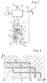
- the clutch 5 comprises a clutch cover 9 held on a flywheel 7 of the engine 1 and a clutch with a friction lining that is guided in a rotationally fixed manner on an input shaft 11 of the transmission 3 provided clutch disc 13.
- a pressure plate 15 which is non-rotatably but axially movably guided on the housing 9 is pressed by a diaphragm spring 17 towards the flywheel 7 and clamps the clutch disc 13 between itself and the flywheel 7.
- An in particular electromotive actuator 19 engages or disengages the clutch 5 via a release system 21 depending on control signals from a control circuit 23 designed as a microprocessor.
- the control circuit 23 detects the motor speed as the input speed of the clutch 5 by means of a speed sensor 25 and the output speed of the clutch 5 occurring on the input shaft of the transmission 3 by means of a speed sensor 27, depending on at least the motor speed and possibly further parameters, in particular those detected by means of a position sensor 29 Position of an accelerator pedal 31 of the motor vehicle, the control circuit 23 controls the engagement of the clutch 5.
- the control circuit 23 differentiates here in a manner known per se between start-up situations and situations in which the transmission 3 is shifted while driving. In both cases, the rate at which the actuator 19 engages the clutch 5 is controlled during engagement so that the clutch is engaged as smoothly as possible.
- the control circuit 23 also monitors the temperature load on the clutch 5 and automatically reduces the temperature load, insofar as this is possible without impairing the function of the clutch.
- the control circuit 23 uses a torque map of the engine 1 stored in a data memory 33 to determine the engine torque assigned to the current position of the accelerator pedal 31 and the current engine speed and multiplies the engine torque by the difference between the engine speed or the engine speed sensors 25, 27. Transmission input speed.
- the on this way, friction power data determined periodically are summed up in a plurality of time window memories in the manner explained in more detail below.
- the time window memories thus contain friction work averages.
- the time window memories have different time windows and thus cover a spectrum that covers the thermal load on the coupling for both short-term peak loads and medium-term and long-term permanent loads.
- the control circuit 23 monitors the thermal load on the clutch 5 as a function of limit values with which it compares the content of the individual time window memories. Several time limits are assigned to each time window memory, the value of which varies depending on the coupling temperature. For this purpose, the arithmetic circuit 23 is connected to a temperature sensor 35, which measures the air temperature in a clutch bell 37 surrounding the clutch 5. The size of the limit values assigned to the individual time window memories is staggered, so that different protective measures or warning measures can be triggered if the individual limit values are exceeded.
- the limit values of the other time window memories differ only in the absolute values W, which increase with increasing size of the time window used for averaging, and they can differ from the example in FIG. 2 by the temperature dependence of the limits.
- the safety measures of the control circuit 23 depend on the limit (W) -temperature (T) range the clutch 5 is. No overload protection measures are taken in the simply hatched area delimited by the temperature axis and the boundary line WI. In the area between the boundary lines WI and WII, indicated by solid and dashed hatching lines, the engagement rate normally determined by the control circuit 23 during engagement is increased by 50%. In addition, the control circuit 23 also reduces an additional slip of the clutch that is possibly predetermined for the reduction of torsional vibrations by approximately 50%. This measure reduces clutch comfort and driving comfort. At the same time, however, the frictional load on the clutch is reduced.
- the transition slip of the clutch is reduced to a minimum, that is to say the delivery rate of the clutch increased to a maximum and a slip control provided for damping torsional vibrations is switched off.
- the clutch actuator is set in a forced oscillation in addition to the reduction of the transitional slip explained above and in addition to the switching off of a possible slip control, which the driver calls "plucking""of the clutch.
- the control circuit 23 signals the impending overload of the clutch via a warning signal 39 (FIG. 1).
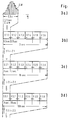
- FIGS. 3a to 3d show the friction work values as surfaces W as they are for the control circuit in the computer clock successively represent as friction power data multiplied by the computer clock period.
- Each of the time window memories comprises 6 memory levels S1.1 to S1.6, S2.1 to S2.6, S3.1 to S3.6 etc.
- the memory levels S1.1 to S1.6 form the time window memory with the smallest time window.
- the friction power values calculated in the computer cycle are summed up in the first stage S1.1. Every 0.5 seconds, the content of memory levels S1.1 to S1.6 is shifted by one memory level, as indicated by arrows.
- the memory level S1.6 is overwritten, while the memory level S1.1 is deleted and the accumulation of friction power data begins again.
- the friction work mean value Z1 is formed every 0.5 seconds over a time window of 3 seconds by summing the contents of the storage stages S1.1 to S1.6.
- the average friction work value Z1 is compared with the limit values WI, WII and WIII predetermined for this time window memory, and the bell air temperature is used to check whether protective measures have to be taken.
- the average friction work value Z1 is based on new data every 3 seconds.
- the friction work averages Z1 in succession in 0.5 second cycles are summed up in a similar manner to the first time window memory in the first memory stage S2.1 of the second time window memory, and in an update cycle multiplied by the number of memory stages, here with a period of 3 seconds, from one memory stage to the next pushed.
- the last storage level S2.6 is again overwritten, while the first storage level S2.1 is deleted after totaling 6 values Z1.
- the content of the 6 storage levels S2.1 to S2.6 are summed up.
- the resulting average friction work value Z2 is thus averaged over a time window of 18 seconds.
- the average friction work value is updated, ie after every 3 seconds, the average friction work value is compared with the associated limit values of the second time window memory, and protective measures are initiated depending on the bell air temperature.
- the organization of the memory levels S3.1 to S3.6 of the third time window memory is analogous to the above memories, but the update period is now 18 seconds and the time window 108 seconds.
- the update periods of further time window memories are accordingly 108 seconds, 648 seconds and 3888 seconds. With 6 time window memories, a time window of 6 hours can be realized.
- the control circuit 23 also reacts to the slip duration of the clutch. If an attempt is made on an incline to prevent the motor vehicle from rolling back by pressing the accelerator pedal 31 and consequently letting the clutch slip, then the control circuit 23 triggers the aforementioned oscillating movement of the actuator after a predetermined period of time, for example 5 seconds after the start of the grinding process 19 of the clutch. The "jerking" of the clutch and the associated reduction in comfort usually cause the driver to change his behavior. In addition, the control circuit 23 can switch on the warning signal 39.
- a torque map of the engine was used to determine the friction power data.
- a correction value is subtracted from each torque value read from the engine map, which the control circuit 23 calculates by multiplying the value of the temporal change in the engine speed by a value representing the moment of inertia of the engine .
- a stored clutch torque map can also be used, in which the clutch torque is stored, for example, as a function of the position of the release system 21. The position of the release system 21 is known to the control circuit 23 via signals from a position sensor (not shown) of the actuator 19.
Landscapes
- Physics & Mathematics (AREA)
- Fluid Mechanics (AREA)
- Engineering & Computer Science (AREA)
- General Engineering & Computer Science (AREA)
- Mechanical Engineering (AREA)
- Hydraulic Clutches, Magnetic Clutches, Fluid Clutches, And Fluid Joints (AREA)
- Mechanical Operated Clutches (AREA)
Applications Claiming Priority (2)
| Application Number | Priority Date | Filing Date | Title |
|---|---|---|---|
| DE4100091A DE4100091C2 (de) | 1991-01-04 | 1991-01-04 | Anordnung zur Überwachung einer Reibungskupplung |
| DE4100091 | 1991-01-04 |
Publications (3)
| Publication Number | Publication Date |
|---|---|
| EP0493840A2 true EP0493840A2 (fr) | 1992-07-08 |
| EP0493840A3 EP0493840A3 (fr) | 1994-03-23 |
| EP0493840B1 EP0493840B1 (fr) | 1995-12-13 |
Family
ID=6422535
Family Applications (1)
| Application Number | Title | Priority Date | Filing Date |
|---|---|---|---|
| EP91122390A Expired - Lifetime EP0493840B1 (fr) | 1991-01-04 | 1991-12-30 | Appareil pour surveiller un embrayage à friction |
Country Status (5)
| Country | Link |
|---|---|
| US (1) | US5337866A (fr) |
| EP (1) | EP0493840B1 (fr) |
| JP (1) | JPH04302717A (fr) |
| BR (1) | BR9200014A (fr) |
| DE (2) | DE4100091C2 (fr) |
Cited By (5)
| Publication number | Priority date | Publication date | Assignee | Title |
|---|---|---|---|---|
| FR2729896A1 (fr) * | 1995-01-28 | 1996-08-02 | Luk Getriebe Systeme Gmbh | Dispositif et procede pour commander un systeme de transmission de couple |
| WO1997017552A1 (fr) * | 1995-11-03 | 1997-05-15 | Robert Bosch Gmbh | Systeme de commande d'embrayage automatique |
| WO2004031604A1 (fr) * | 2002-10-01 | 2004-04-15 | Eaton Corporation | Systeme de protection d'embrayage |
| WO2004040159A1 (fr) * | 2002-10-31 | 2004-05-13 | Eaton Corporation | Systeme de protection d'embrayage |
| WO2007076935A1 (fr) * | 2005-12-23 | 2007-07-12 | Borgwarner Inc. | Mesure de l'homogeneite de couple pour des embrayages a disques multiples |
Families Citing this family (34)
| Publication number | Priority date | Publication date | Assignee | Title |
|---|---|---|---|---|
| GB2310473B (en) * | 1993-08-03 | 1998-03-11 | Luk Getriebe Systeme Gmbh | Motor vehicle clutch control |
| DE4337021C2 (de) * | 1993-10-29 | 1998-04-09 | Daimler Benz Ag | Vorrichtung zum Steuern einer die Drehzahldifferenz einer Kupplung eines Kraftfahrzeuges bestimmenden Stellgröße |
| DE19529462B4 (de) * | 1995-08-10 | 2004-09-02 | Iav Gmbh Ingenieurgesellschaft Auto Und Verkehr | Einrichtung zur Drehmomentermittlung für eine Antriebseinheit mit einem Verbrennungsmotor |
| DE19600739A1 (de) * | 1996-01-11 | 1997-07-17 | Zahnradfabrik Friedrichshafen | Getriebesteuerung zur Reduzierung der thermischen Belastung von Schaltelementen |
| FR2749627B1 (fr) * | 1996-06-10 | 1998-08-28 | Valeo | Module d'embrayage comportant une cible associee a un capteur de rotation venue de matiere avec le couvercle du module d'embrayage |
| GB2327248B (en) * | 1997-04-09 | 2001-05-16 | Luk Getriebe Systeme Gmbh | Motor vehicle with a power train having an automated clutch |
| DE19721298C2 (de) * | 1997-05-21 | 2001-09-06 | Mannesmann Sachs Ag | Hybrid-Fahrantrieb für ein Kraftfahrzeug |
| NO982430L (no) * | 1997-06-04 | 1998-12-07 | Luk Getriebe Systeme Gmbh | FremgangsmÕte for drift av en automatkopling samt for kontrollering av en temperatursensor |
| DE19810033A1 (de) * | 1998-03-09 | 1999-09-16 | Mannesmann Sachs Ag | Anordnung zur Überwachung des Verschleißzustandes einer Reibungskupplung |
| GB2372330B (en) * | 1998-03-09 | 2003-04-23 | Zf Sachs Ag | An arrangement for and a method of monitoring the state of wear of a motor vehicle friction clutch |
| DE19946334A1 (de) | 1998-10-08 | 2000-04-13 | Luk Getriebe Systeme Gmbh | Kraftfahrzeug |
| WO2001062536A1 (fr) * | 2000-02-24 | 2001-08-30 | Luk Lamellen Und Kupplungsbau Beteiligungs Kg | Dispositif et procede d'actionnement automatique d'un embrayage |
| US6633806B2 (en) * | 2001-08-30 | 2003-10-14 | Eaton Corporation | Control for transmission system utilizing a centrifugal clutch |
| DE10233699A1 (de) * | 2002-07-24 | 2004-02-19 | Voith Turbo Gmbh & Co. Kg | Verfahren und Vorrichtung zur Früherkennung von Störfällen beim Betrieb automatischer oder automatisierter Getriebe |
| FR2855573B1 (fr) * | 2003-05-26 | 2006-07-14 | Renault Sa | Procede de detection d'usure d'un embrayage pilote |
| AU2003294850A1 (en) | 2003-12-13 | 2005-06-29 | Gkn Driveline International Gmbh | Method for determining the disc temperature of a multi-disc clutch |
| DE50310176D1 (de) * | 2003-12-13 | 2008-08-28 | Gkn Driveline Int Gmbh | Verfahren zur temperaturabhängigen regelung einer lamellenkupplung |
| US7101310B2 (en) * | 2004-04-19 | 2006-09-05 | Magna Powertrain Usa, Inc. | Model-based control for torque biasing system |
| DE502005003425D1 (de) * | 2004-08-04 | 2008-05-08 | Luk Lamellen & Kupplungsbau | Verfahren zum Schutz einer automatisiert betätigten Kupplung eines Fahrzeugs gegen Überlastung |
| DE102005026615A1 (de) * | 2005-06-09 | 2006-12-14 | Zf Friedrichshafen Ag | Verfahren und Vorrichtung zur Steuerung einer automatisierten Reibkupplung zwischen einem Motor und einem Getriebe |
| DE102006024290A1 (de) * | 2006-05-24 | 2007-11-29 | Zf Friedrichshafen Ag | Verfahren zum Betrieb einer automatisierten Reibungskupplung |
| DE102006058724B3 (de) * | 2006-12-13 | 2008-04-17 | Dr.Ing.H.C. F. Porsche Ag | Verfahren zum Schutz einer Kupplung in einem Triebstrang eines Kraftfahrzeugs |
| CN103261724B (zh) | 2010-08-23 | 2016-05-04 | 舍弗勒技术股份两合公司 | 摩擦离合器 |
| US8731793B2 (en) * | 2010-12-29 | 2014-05-20 | Caterpillar Inc. | Clutch temperature estimation for a mobile machine |
| DE102011089031B4 (de) * | 2011-12-19 | 2026-04-02 | Zf Friedrichshafen Ag | Verfahren und Steuerungseinrichtung zur Bestimmung eines Berührpunkts einer Reibkupplung |
| US9090240B2 (en) * | 2012-03-05 | 2015-07-28 | GM Global Technology Operations LLC | Dual-clutch transmission predictive thermal protection |
| DE102013204667A1 (de) * | 2013-03-18 | 2014-09-18 | Zf Friedrichshafen Ag | Verfahren zur Durchführung einer Wendeschaltung |
| DE102013204666A1 (de) * | 2013-03-18 | 2014-09-18 | Zf Friedrichshafen Ag | Verfahren zur Durchführung einer Gangschaltung |
| DE112017000875B4 (de) | 2016-02-19 | 2023-07-13 | Schaeffler Technologies AG & Co. KG | Verfahren zum Berechnen einer Schlupfleistung einer Hybridtrennkupplung |
| WO2019072383A1 (fr) * | 2017-10-11 | 2019-04-18 | Volvo Truck Corporation | Procédé de commande d'un arrangement d'embrayage |
| CN112594376B (zh) * | 2020-12-27 | 2022-06-28 | 潍柴动力股份有限公司 | 一种hmcvt的换挡控制方法及相关装置 |
| US12494723B2 (en) | 2021-03-31 | 2025-12-09 | Honda Motor Co., Ltd. | Clutch control apparatus |
| CN115823146B (zh) * | 2022-12-29 | 2025-06-03 | 蜂巢传动系统(江苏)有限公司 | K0离合器的过热保护方法及混合动力汽车 |
| CN116816830B (zh) * | 2023-06-28 | 2025-12-26 | 潍柴动力股份有限公司 | Amt气动离合器的预测控制方法、装置、设备及介质 |
Family Cites Families (14)
| Publication number | Priority date | Publication date | Assignee | Title |
|---|---|---|---|---|
| US4509625A (en) * | 1980-07-25 | 1985-04-09 | Sachs-Systemtechnik Gmbh | Automatic friction clutches and controls therefor |
| DE3214494A1 (de) * | 1982-04-20 | 1983-10-20 | Sachs Systemtechnik Gmbh, 8720 Schweinfurt | Vorrichtung zur automatischen betaetigung einer kraftfahrzeug-reibungskupplung |
| JPS6034525A (ja) * | 1983-08-05 | 1985-02-22 | Fujitsu Ltd | クラツチ制御装置 |
| DE3404156A1 (de) * | 1984-02-07 | 1985-08-14 | Daimler-Benz Ag, 7000 Stuttgart | Einrichtung zur automatischen betaetigung einer kupplung von fahrzeugen waehrend des anfahrens |
| DE3437808C2 (de) * | 1984-10-16 | 1987-05-07 | MEC Maschinenbau Entwicklung Consulting GmbH, 5180 Eschweiler | Verfahren zum lastabhängigen Auslösen einer Sicherheitskupplung an einer Maschinenanlage und Drehmomentüberwachungssystem zur Durchführung des Verfahrens |
| DE3540719A1 (de) * | 1984-12-01 | 1986-06-05 | Zahnradfabrik Friedrichshafen Ag, 7990 Friedrichshafen | Einrichtung zum ueberlastschutz fuer reibkupplungen |
| JPS61197824A (ja) * | 1985-02-28 | 1986-09-02 | Isuzu Motors Ltd | クラツチ制御装置 |
| DE3601708A1 (de) * | 1986-01-22 | 1987-07-23 | Sachs Systemtechnik Gmbh | Anordnung zur ueberwachung einer reibungskupplung insbesondere eines kraftfahrzeugs |
| EP0352277B1 (fr) * | 1987-03-26 | 1990-10-31 | ZF FRIEDRICHSHAFEN Aktiengesellschaft | Systeme de commande d'un embrayage automatique de vehicule a moteur |
| DE3737899A1 (de) * | 1987-11-07 | 1989-08-03 | Sachs Systemtechnik Gmbh | Vorrichtung zur automatischen betaetigung einer reibungskupplung |
| DE3800607A1 (de) * | 1988-01-12 | 1989-07-20 | Kloeckner Humboldt Deutz Ag | Kupplung |
| DE3828128C2 (de) * | 1988-08-18 | 1996-10-31 | Fichtel & Sachs Ag | Anordnung zur Überwachung einer Reibungskupplung |
| JPH03255261A (ja) * | 1990-03-05 | 1991-11-14 | Mazda Motor Corp | 自動変速機の制御装置 |
| DE4021736C2 (de) * | 1990-06-01 | 2000-05-25 | Mannesmann Sachs Ag | Vorrichtung zur Temperaturmessung an beweglichen Teilen |
-
1991
- 1991-01-04 DE DE4100091A patent/DE4100091C2/de not_active Expired - Fee Related
- 1991-12-27 JP JP3346406A patent/JPH04302717A/ja active Pending
- 1991-12-27 US US07/815,272 patent/US5337866A/en not_active Expired - Fee Related
- 1991-12-30 EP EP91122390A patent/EP0493840B1/fr not_active Expired - Lifetime
- 1991-12-30 DE DE59107079T patent/DE59107079D1/de not_active Expired - Fee Related
-
1992
- 1992-01-03 BR BR929200014A patent/BR9200014A/pt not_active Application Discontinuation
Cited By (9)
| Publication number | Priority date | Publication date | Assignee | Title |
|---|---|---|---|---|
| FR2729896A1 (fr) * | 1995-01-28 | 1996-08-02 | Luk Getriebe Systeme Gmbh | Dispositif et procede pour commander un systeme de transmission de couple |
| FR2771346A1 (fr) * | 1995-01-28 | 1999-05-28 | Luk Getriebe Systeme Gmbh | Dispositif et procede pour commander un systeme de transmission de couple |
| WO1997017552A1 (fr) * | 1995-11-03 | 1997-05-15 | Robert Bosch Gmbh | Systeme de commande d'embrayage automatique |
| WO2004031604A1 (fr) * | 2002-10-01 | 2004-04-15 | Eaton Corporation | Systeme de protection d'embrayage |
| US6943676B2 (en) | 2002-10-01 | 2005-09-13 | Eaton Corporation | Clutch protection system |
| WO2004040159A1 (fr) * | 2002-10-31 | 2004-05-13 | Eaton Corporation | Systeme de protection d'embrayage |
| US6888273B2 (en) | 2002-10-31 | 2005-05-03 | Eaton Corporation | Integrated motor and clutch assembly |
| WO2007076935A1 (fr) * | 2005-12-23 | 2007-07-12 | Borgwarner Inc. | Mesure de l'homogeneite de couple pour des embrayages a disques multiples |
| US8225650B2 (en) | 2005-12-23 | 2012-07-24 | Borgwarner Inc. | Measurement of torque uniformity in multiplate clutches |
Also Published As
| Publication number | Publication date |
|---|---|
| DE4100091A1 (de) | 1992-07-09 |
| BR9200014A (pt) | 1992-11-10 |
| EP0493840A3 (fr) | 1994-03-23 |
| JPH04302717A (ja) | 1992-10-26 |
| US5337866A (en) | 1994-08-16 |
| DE4100091C2 (de) | 2002-01-10 |
| DE59107079D1 (de) | 1996-01-25 |
| EP0493840B1 (fr) | 1995-12-13 |
Similar Documents
| Publication | Publication Date | Title |
|---|---|---|
| DE4100091C2 (de) | Anordnung zur Überwachung einer Reibungskupplung | |
| EP1626884B1 (fr) | Procede et systeme pour commander un systeme de freinage equipe d'un frein de stationnement electrique | |
| DE60320120T2 (de) | Kupplungsschutzsystem | |
| DE19758517B4 (de) | Vorrichtung und Verfahren zur Betätigung einer im Antriebsstrang eines Fahrzeuges zwischen einem Antriebsaggregat und einem Getriebe angeordneten Kupplung und/oder des Getriebes | |
| DE19818809B4 (de) | Vorrichtung zur Ansteuerung einer Kupplung | |
| EP1474306B1 (fr) | Procede pour empecher un moteur d'automobile de caler | |
| DE19602006A1 (de) | Vorrichtung und ein Verfahren zur Ansteuerung eines Drehmomentübertragungssystems | |
| DE2754852A1 (de) | Integrierte betriebsverlauf-aufzeichnungseinrichtung fuer gasturbinentriebwerke | |
| EP1560737B1 (fr) | Procede et dispositif pour reguler le systeme de freinage d'une automobile | |
| DE4235364C2 (de) | Verfahren zum Erfassen der Temperatur einer Scheibenbremse | |
| EP1447583B1 (fr) | Procédé de mise en oeuvre d'une stratégie de protection de l'embrayage de la boîte de vitesses automatique d'un véhicule | |
| DE102005061080A1 (de) | Verfahren und Vorrichtung zum Erkennen einer Schädigung einer Kupplung mit wenigstens zwei durch Reibeingriff Drehmoment übertragenden Bauteilen | |
| DE4337021C2 (de) | Vorrichtung zum Steuern einer die Drehzahldifferenz einer Kupplung eines Kraftfahrzeuges bestimmenden Stellgröße | |
| DE10135899A1 (de) | Steuerung eines automatisierten Anfahrelements | |
| DE4135969B4 (de) | Verfahren zum Steuern einer automatischen Startkupplung | |
| DE19921920A1 (de) | Verfahren zum Schützen einer automatisierten Reibungskupplung eines Fahrzeugs gegen Überlastung | |
| DE19750824C2 (de) | Verfahren zur Erfassung einer Grenzstellungsposition einer Kraftfahrzeugkupplung | |
| DE102015208854A1 (de) | Verfahren zum Schutz einer Kupplung eines Kraftfahrzeuges | |
| EP1775449A1 (fr) | Ligne de transmission pour véhicule et méthode pour l'utilisation d'une telle ligne de transmission | |
| EP1692411B1 (fr) | Procede pour reguler un embrayage a disques en fonction de la temperature | |
| DE112010003238B4 (de) | Verfahren zur steuerung eines kriechvorgangs eines kraftfahrzeugs | |
| DE60113517T2 (de) | Verfahren und vorrichtung zur anzeigung eines schlupfzustands | |
| DE112005000272T5 (de) | Anordnung und Verfahren zum Abbremsen eines Kraftfahrzeugs | |
| EP3253627B1 (fr) | Unité de commande et procédé destiné à empêcher un déplacement involontaire d'un véhicule | |
| DE102007048528A1 (de) | Verfahren zur Steuerung einer Rückregelstrategie einer hydrodynamischen Bremse |
Legal Events
| Date | Code | Title | Description |
|---|---|---|---|
| PUAI | Public reference made under article 153(3) epc to a published international application that has entered the european phase |
Free format text: ORIGINAL CODE: 0009012 |
|
| AK | Designated contracting states |
Kind code of ref document: A2 Designated state(s): DE FR GB IT SE |
|
| PUAL | Search report despatched |
Free format text: ORIGINAL CODE: 0009013 |
|
| AK | Designated contracting states |
Kind code of ref document: A3 Designated state(s): DE FR GB IT SE |
|
| 17P | Request for examination filed |
Effective date: 19940505 |
|
| 17Q | First examination report despatched |
Effective date: 19941227 |
|
| GRAA | (expected) grant |
Free format text: ORIGINAL CODE: 0009210 |
|
| AK | Designated contracting states |
Kind code of ref document: B1 Designated state(s): DE FR GB IT SE |
|
| ITF | It: translation for a ep patent filed | ||
| GBT | Gb: translation of ep patent filed (gb section 77(6)(a)/1977) |
Effective date: 19951213 |
|
| REF | Corresponds to: |
Ref document number: 59107079 Country of ref document: DE Date of ref document: 19960125 |
|
| ET | Fr: translation filed | ||
| PLBE | No opposition filed within time limit |
Free format text: ORIGINAL CODE: 0009261 |
|
| STAA | Information on the status of an ep patent application or granted ep patent |
Free format text: STATUS: NO OPPOSITION FILED WITHIN TIME LIMIT |
|
| 26N | No opposition filed | ||
| PGFP | Annual fee paid to national office [announced via postgrant information from national office to epo] |
Ref country code: SE Payment date: 19991125 Year of fee payment: 9 |
|
| PGFP | Annual fee paid to national office [announced via postgrant information from national office to epo] |
Ref country code: GB Payment date: 20001115 Year of fee payment: 10 |
|
| PGFP | Annual fee paid to national office [announced via postgrant information from national office to epo] |
Ref country code: FR Payment date: 20001204 Year of fee payment: 10 |
|
| PG25 | Lapsed in a contracting state [announced via postgrant information from national office to epo] |
Ref country code: SE Free format text: LAPSE BECAUSE OF NON-PAYMENT OF DUE FEES Effective date: 20001231 |
|
| EUG | Se: european patent has lapsed |
Ref document number: 91122390.7 |
|
| PG25 | Lapsed in a contracting state [announced via postgrant information from national office to epo] |
Ref country code: GB Free format text: LAPSE BECAUSE OF NON-PAYMENT OF DUE FEES Effective date: 20011230 |
|
| REG | Reference to a national code |
Ref country code: GB Ref legal event code: IF02 |
|
| GBPC | Gb: european patent ceased through non-payment of renewal fee |
Effective date: 20011230 |
|
| PG25 | Lapsed in a contracting state [announced via postgrant information from national office to epo] |
Ref country code: FR Free format text: LAPSE BECAUSE OF NON-PAYMENT OF DUE FEES Effective date: 20020830 |
|
| REG | Reference to a national code |
Ref country code: FR Ref legal event code: ST |
|
| PG25 | Lapsed in a contracting state [announced via postgrant information from national office to epo] |
Ref country code: IT Free format text: LAPSE BECAUSE OF NON-PAYMENT OF DUE FEES;WARNING: LAPSES OF ITALIAN PATENTS WITH EFFECTIVE DATE BEFORE 2007 MAY HAVE OCCURRED AT ANY TIME BEFORE 2007. THE CORRECT EFFECTIVE DATE MAY BE DIFFERENT FROM THE ONE RECORDED. Effective date: 20051230 |
|
| PGFP | Annual fee paid to national office [announced via postgrant information from national office to epo] |
Ref country code: DE Payment date: 20071231 Year of fee payment: 17 |
|
| PG25 | Lapsed in a contracting state [announced via postgrant information from national office to epo] |
Ref country code: DE Free format text: LAPSE BECAUSE OF NON-PAYMENT OF DUE FEES Effective date: 20090701 |