EP0493845A2 - Gehäuse für eine rechteckige Kassette - Google Patents
Gehäuse für eine rechteckige Kassette Download PDFInfo
- Publication number
- EP0493845A2 EP0493845A2 EP91203104A EP91203104A EP0493845A2 EP 0493845 A2 EP0493845 A2 EP 0493845A2 EP 91203104 A EP91203104 A EP 91203104A EP 91203104 A EP91203104 A EP 91203104A EP 0493845 A2 EP0493845 A2 EP 0493845A2
- Authority
- EP
- European Patent Office
- Prior art keywords
- holder
- cassette
- wall
- enclosure
- space
- Prior art date
- Legal status (The legal status is an assumption and is not a legal conclusion. Google has not performed a legal analysis and makes no representation as to the accuracy of the status listed.)
- Granted
Links
- 210000003813 thumb Anatomy 0.000 claims abstract description 15
- 238000000034 method Methods 0.000 claims description 32
- 229920003023 plastic Polymers 0.000 claims description 20
- 238000003780 insertion Methods 0.000 claims description 18
- 230000037431 insertion Effects 0.000 claims description 18
- 230000007246 mechanism Effects 0.000 claims description 17
- 238000003032 molecular docking Methods 0.000 claims description 15
- 239000004033 plastic Substances 0.000 claims description 13
- 239000000463 material Substances 0.000 claims description 11
- PPBRXRYQALVLMV-UHFFFAOYSA-N Styrene Chemical compound C=CC1=CC=CC=C1 PPBRXRYQALVLMV-UHFFFAOYSA-N 0.000 claims description 6
- 229920001400 block copolymer Polymers 0.000 claims description 3
- 238000004891 communication Methods 0.000 claims description 3
- 238000003466 welding Methods 0.000 description 5
- 238000010276 construction Methods 0.000 description 3
- 210000004247 hand Anatomy 0.000 description 2
- 238000004519 manufacturing process Methods 0.000 description 2
- 229920000298 Cellophane Polymers 0.000 description 1
- 239000000969 carrier Substances 0.000 description 1
- 239000013536 elastomeric material Substances 0.000 description 1
- 239000011888 foil Substances 0.000 description 1
- 238000001746 injection moulding Methods 0.000 description 1
- 230000003287 optical effect Effects 0.000 description 1
- 230000002441 reversible effect Effects 0.000 description 1
Images


Classifications
-
- G—PHYSICS
- G11—INFORMATION STORAGE
- G11B—INFORMATION STORAGE BASED ON RELATIVE MOVEMENT BETWEEN RECORD CARRIER AND TRANSDUCER
- G11B23/00—Record carriers not specific to the method of recording or reproducing; Accessories, e.g. containers, specially adapted for co-operation with the recording or reproducing apparatus ; Intermediate mediums; Apparatus or processes specially adapted for their manufacture
- G11B23/02—Containers; Storing means both adapted to cooperate with the recording or reproducing means
-
- G—PHYSICS
- G11—INFORMATION STORAGE
- G11B—INFORMATION STORAGE BASED ON RELATIVE MOVEMENT BETWEEN RECORD CARRIER AND TRANSDUCER
- G11B23/00—Record carriers not specific to the method of recording or reproducing; Accessories, e.g. containers, specially adapted for co-operation with the recording or reproducing apparatus ; Intermediate mediums; Apparatus or processes specially adapted for their manufacture
- G11B23/02—Containers; Storing means both adapted to cooperate with the recording or reproducing means
- G11B23/023—Containers for magazines or cassettes
- G11B23/0233—Containers for a single cassette
Definitions
- the invention relates to a holder for a rectangular cassette provided with a recording medium, which cassette has a cassette main wall optionally provided with a label, which holder comprises a front wall having a window and a rear wall which are parallel to the cassette main wall, two long side walls, one short bottom wall, and one open side opposite the short bottom wall, said walls bounding a cassette-receiving space in the holder into which the cassette can be inserted via the open side.
- a holder of this type is known from FR-PA 2,632,759 as a container for video cassettes.
- One of the short sides is open for inserting a cassette into or removing it from the cassette-receiving space.
- the holder is made of a plastics and has a narrow plastics window.
- One of the long sides of the holder is also transparent.
- the pictorial and text information is provided respectively on and in the package.
- the cassette itself can be provided with a decorative and informative label which largely covers one main wall of the cassette.
- the back of the cassette may also be provided with a label.
- this label is much smaller and can therefore accommodate only a minimum of information which, moreover, can be read only at close range, as with the afore-mentioned video cassettes.
- the invention aims at providing a holder of the type defined in the opening paragraph which enables said disadvantages to be avoided and is characterised in that the window comprises an open part in the front wall, which open part is dimensioned in such a way that, when the holder is held in the palm of a hand, the cassette can be pushed at least partly out of the holder with the thumb of the same hand on a cassette main wall.
- the label is protected by a transparent cover connected to the cassette.
- a transparent cover connected to the cassette.
- an embodiment of the invention is used which is characterised in that the dimensions of the window are substantially equal to the dimensions of the label of the cassette.
- the use of this embodiment enables all the relevant pictorial and text information on the cassette to be observed at a glance by a user from the outside of the holder, while at the same time all the non-relevant parts of the cassette are covered.
- a further characteristic feature of the invention is important, which characteristic feature is that the holder comprises internal holding means for clamping a cassette which has been inserted into the cassette receiving space.
- the holding means comprise an elastic holding member which is situated in a transverse wall of the holder and which is deformed elastically by an inserted cassette.
- the holding member is made of a material which is comparatively easy to deform in comparison with the material of the holder.
- the holding member comprises a plug arranged in an opening in a transverse wall of the holder.
- Tests have shown that the use of the above-mentioned embodiments effectively prevent the cassette from inadvertently falling out of the holder.
- the rubber-like properties of the holding member preclude damage to the cassette and to the holder.
- an embodiment of the invention is of importance, which is characterised in that at the side opposite the window the holder has an internal enclosure space for the insertion of an enclosure, which may comprise a plurality of pages, and in the absence of a cassette the enclosure is visible from the outside through the window in the front wall of the holder.
- an advantageous embodiment which is very suitable for the "dead” sale of digital music cassettes, is characterised in that at its side which faces the cassette receiving space the enclosure is given an appearance which is similar to the appearance of the label of the cassette. It will be obvious that the information on the enclosure which faces the interior of the holder will be of little significance to an owner of a digital music cassette.
- a further embodiment which is of interest is characterised in that the enclosure space communicates with a flap space adjacent a side wall of the holder and the enclosure has a side flap which extends in the flap space.
- this embodiment is of particular interest when the flap can be provided with text and/or pictorial information which is always visible from the outside of the cassette.
- an embodiment of the invention is used which is characterised in that the holder comprises two separate sections which are secured to one another and which each comprise a main wall and an adjoining transverse wall. It is then advantageous, also because the holder has an enclosure space and a flap space, to use an embodiment which is characterised in that one section comprises the front wall with an adjoining side wall and the rear wall the other section comprises the other side wall.
- the holder in accordance with the invention has the advantage of a simple construction requiring a small amount of material.
- the holder does not comprise any moving parts and, moreover, the holder requires only two parts which can be manufactured from a plastics by means of well-known injection-moulding techniques.
- An embodiment which is of interest for the visibility of an enclosure in the holder is characterised in that said other section is made of a transparent plastics.
- this embodiment is combined with a further embodiment which is characterised in that said one section is made of a non-transparent plastics and substantially covers those parts of a cassette present in the holder which adjoin the label.
- An embodiment of the invention which is of interest to facilitate the manufacture of the holder and also to minimize material consumption is characterised in that the enclosure space is in open communication with the cassette receiving space and between the enclosure space and the cassette receiving space inside the holder ridges are formed at opposite sides for cooperation with the side edges of the enclosure.
- an embodiment is of interest which is characterised in that an internal transverse wall, which forms part of one of the sections of the holder, is interposed between the flap space and the cassette receiving space in such a manner that the flap space is bounded by a side wall and the internal transverse wall.
- An additional advantage of this embodiment is that if the cassette is not situated correctly in the holder the flap is nevertheless enclosed correctly in the flap space and, moreover, that the cassette receiving space is distinctly bounded, which is important in view of the afore-mentioned "dead" sale of the digital music cassette.
- the holder in accordance with the invention comprises only a small number of parts, does not require any moving parts, and offers a high degree of functionality, as already set forth hereinbefore.
- an embodiment may be used which is characterised in that the open side of the holder can be covered with a cover which is pivotally connected to the holder. This embodiment provides an additional guarantee that the cassette cannot readily fall out of the container.
- Another advantage is that the holder has an attractive enclosed appearance.
- Another interesting embodiment of the invention is characterised in that the cover is connected to a main wall by a plastics integral hinge. Consequently, it is not necessary to provide the holder with separate parts.
- a further embodiment which is of interest is characterised in that the cover is pivotally connected to the rear wall of the holder and there is provided a spring mechanism permitting the cover to assume only two stable positions, i.e. either a fully closed position or a fully open position.
- the transparent part of the holder is made of a styrene/butadiene-block copolymer. Plastics of this type are suitable for forming integral hinge constructions and are available in a glass-clear quality.
- the holder has a plurality of cassette-receiving spaces. Consequently, the holder in accordance with the invention is also suitable for holding two or more cassettes, for example in the case that a recording cannot be accommodated on a single recording medium.
- the invention relates not only to a holder for a rectangular cassette but also to a method of removing a cassette from a holder, i.e. by taking the holder with the cassette held therein in one hand, pushing the cassette at least partly out of an open side of the holder with the thumb of the same hand through an opening in a wall of the holder, and subsequently removing it completely from the holder.
- a method of removing a cassette from a holder i.e. by taking the holder with the cassette held therein in one hand, pushing the cassette at least partly out of an open side of the holder with the thumb of the same hand through an opening in a wall of the holder, and subsequently removing it completely from the holder.
- a method is particularly advantageous when cassettes are used in automotive or portable apparatus.
- Such a method is of particular advantage if it is combined with the loading of the cassette into an apparatus via a slot in the front panel of said apparatus, the method comprising the insertion of the part of the cassette which has been pushed out of the holder into the slot, after which the cassette is gripped by a loading mechanism of the apparatus, which mechanism pulls the cassette further out of the holder and into the apparatus.
- This method of loading a cassette into a playing apparatus minimizes the operations to be performed by the user. The user no longer has to remove the cassette completely from the holder and merely has to push the cassette out of the holder over some distance with his thumb. The remainder of the operation is performed by the loading mechanism of the apparatus.
- the invention provides a further method, comprising the guidance of the holder by guide surfaces provided around the slot to a docking position defined by stop means, in which position the cassette receiving space is disposed in line with the path along which the cassette is moved by the loading mechanism of the apparatus.
- a method comprising the at least partial insertion of the holder with the cassette into an apparatus and the movement of the cassette into/out of the holder by the apparatus itself inside the apparatus. This method leads to further improved user convenience.
- the invention relates not only to the method but also to an apparatus suitable for the method in accordance with the invention.
- an apparatus in accordance with the invention may be characterised in that the apparatus comprises docking means adapted to cooperate with a cassette and comprising stop means which define a docking position for a cassette relative to a path along which the cassette is movable by a loading mechanism of the apparatus.
- the apparatus When an apparatus is adapted, as described above, to push the cassette together with the holder completely or partly into the apparatus, the apparatus will comprise internal means for removal of the cassette from the holder.
- These means may comprise retaining means for retaining the holder, in combination with pushing means for pushing the cassette out of the holder through the window.
- the pushing means may comprise, for example, a pushing member which simulates the function of a user's thumb, or a rotary member which bears resiliently on the cassette with friction and, as it rotates, moves the cassette out of and, if necessary, subsequently moves the cassette back into the holder.
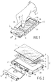
- the holder 1 shown in the drawings is intended as a container for a rectangular cassette 2 .
- this assembly may be wrapped in cellophane or shrink foil in the customary way.
- the cassette is a "digital music cassette", i.e. a cassette with a magnetic tape 3 provided with a music programme in a digital format by a music company.
- the cassette comprises two main walls 4 and 5 at respectively the upper side and the lower side of the cassette.
- the main wall 4 is provided with a label 6 which is made of, for example, paper and which may be provided with pictorial and text information, if desired in colour.
- a transparent cover element 7 To protect the label and to improve the appearance of the cassette the label is covered by a transparent cover element 7.
- the label has a flap 8 which is covered by a corresponding part 9 of the transparent cover element 7.
- the flap is situated at the back 10 of the cassette and may also be provided with pictorial and/or text information.
- a slide 12 is slidable over the front wall 11 of the cassette.
- the slide has two openings 13 and 14 to expose the openings 15, 16 and 17 in the front wall of the cassette in order to allow the entry of a magnetic-head unit, capstans and pressure rollers of an apparatus.
- the slide 12 In the closed position the slide 12 covers two openings 18 and 19 in the bottom wall 5 of the cassette. When the slide is in the open position these openings give drive means of an apparatus access to two reel hubs of the cassette. Resilient means, not shown, urge the slide towards its closed position.
- the slide 12 will be in its closed position, as is shown in Figs. 3 to 5.
- the holder 1 comprises two parallel main walls 20 and 21 and three interconnecting transverse walls.
- the holder also has an open side 25 through which the cassette can be inserted into or removed from the holder.
- the main walls and the transverse walls thus define a cassette receiving space which is accessible via the open side 25.
- the main wall 20 forms a front wall of the holder.
- This front wall has a window 26 through which the label 6 of the cassette 2 present in the holder is visible from the outside.
- the other walls of the holder form a rear wall 21, long side walls 22 and 23, and a short bottom wall 24.
- the holder comprises internal holding means for clamping a cassette inside the cassette receiving space 27.
- These holding means comprise an elastic holding member 28 which is situated in the transverse wall 22 and which is deformed elastically upon insertion of a cassette.
- the holding member is made of a material which is readily deformable in comparison with the material of the holder, i.e. an elastomeric material or another material having rubber-like properties. It is constructed as a plug fitted in an opening 29 in the transverse wall 22, see in particular Figs. 13 and 14.
- the opening 29 has a rectangular shape to avoid rotation of the plug 28.
- the plug has an inclined contact face 30, so that upon insertion of a cassette into the cassette receiving space 27 the plug is deformed gradually.
- the plug cooperates with the part 11a of the front wall 11 of the cassette. In the closed position of the slide this part of the front wall of the cassette is not covered by the slide.
- the housing of the cassette has a ridge 31 which serves as a stop for the slide when the slide is opened.
- the plug 28 is arranged at such a location in the side wall 22 of the holder that upon insertion of a cassette into the holder the ridge 31 moves just past the plug 28, so that the cooperation between the ridge 31 and the plug assists in holding the cassette in the holder.
- the window comprises an open part having dimensions large enough to enable the cassette to be pushed at least partly out of the holder when the holder is held in the palm of one hand with the thumb on the label of the cassette.
- the window 26 is completely open and has a size substantially equal to that of the label of the cassette.
- the holder has a separate enclosure space 32 for the insertion of an enclosure 34, which may comprise a plurality of pages 33.
- the enclosure is shown separately in Fig. 20.
- the enclosure resembles a booklet having a booklet cover 35.
- the enclosure is visible from the outside through the window 26 of the holder. This can be seen in Fig. 1, which shows a part of the cover of the enclosure 34.
- the cover 35 of the enclosure 34 faces the cassette receiving space 27 and has an appearance, i.e. has been provided with pictorial and text information, similar to the appearance of the label 6 of the cassette.
- pictorial and text information visible through the window 26 is always the same, regardless of the presence of the cassette 2 . As already stated hereinbefore, this is important for the "dead" sale of music cassettes.
- the enclosure 34 has a side flap 36.
- this flap is accommodated in a flap space 37 which communicates with the enclosure space 32, see in particular Fig. 7 and Fig. 12.
- the side flap 36 inter alia assists in retaining the enclosure in the enclosure space.
- the holder 1 comprises two separate sections 1A and 1B secured to one another.
- these sections are made of a suitable plastics and can be interconnected by cementing, ultrasonic welding or in any other suitable manner.
- Each of the two sections comprises a main wall and an adjoining transverse wall.
- the section 1A comprises the front wall 20 and the adjoining side wall 22 and bottom wall 24, and the section 1B comprises the rear wall 21 and the adjoining side wall 23.
- the section 1B is made of a transparent plastics, so that after insertion into the holder both the rear of the enclosure 34 and the outwardly facing side of the flap 36 are visible from the outside.
- these parts of the enclosure 34 may also be printed with suitable information for the consumer.
- This information need not be the same as the pictorial and text information provided on the cover 35. Indeed, the last-mentioned information is always, i.e. regardless of the presence of a cassette, visible from the outside. Therefore, the information which is visible from the outside through the transparent window 1B may be additional information.
- the section 1A is made of a non-transparent plastics and this section, see in particular Fig. 1, covers all those parts of a cassette in the holder which adjoin the label 6, so that if a cassette is present the window 26 only exposes the label 6. This also contributes to the structural integrity of the holder.
- the cassette receiving space 27 is in open communication with the enclosure space 32.
- Two ridges 38A and 38B extend between the two spaces inside the holder at opposite sides. In the embodiment shown both ridges form part of the non-transparent section 1A of the holder. The two ridges cooperate with side edges of the enclosure 34 and thus retain this enclosure in the enclosure space.
- An internal transverse wall 39 which forms part of the section 1A of the holder, is situated between the flap space 37 and the cassette receiving space 27. At one side the flap space 37 is thus bounded by the transparent side wall 23 and at the other side by the non-transparent internal transverse wall 39.
- the non-transparent internal wall 39 also helps to ensure that the cover 35 of the enclosure 34 can be read correctly in the absence of a cassette.
- the sections 1A and 1B are permanently joined by ultrasonic welding.
- the section 1A comprises a plurality of thin welding ridges 110 which melt during welding.
- the section 1B also has welding ridges at a location which is not visible in the drawing and which is situated behind the side wall 23.
- the sections 1A and 1B also comprise means for provisionally assembling them, so that if desired the sections can be disassembled for inserting the enclosure before the holder is finally welded.
- Said means comprise snap projections 111 which engage in corresponding recesses 112, and conical pins 113 which fit tightly in recesses, not shown in Fig. 14, in the side wall 23.
- a resilient clamping member 114 for retaining the enclosure is arranged near the bottom wall 24 in line with the ridge 38A.
- the clamping member comprises a blade spring 115 and a run-on projection 116 with a rounded surface 117.
- the clamping member is made of a plastics and is integral with the section 1A.
- the rounded surface 117 ensures a gradual deformation of the blade spring 115 when an enclosure is inserted.
- the enclosure may have an opening corresponding to the run-on projection, so that the enclosure is held even more effectively.
- the transverse wall 39 comprises gradually inclined portions 118, 119.
- a projection 125 at the front of the section 1B constitutes a further means to prevent the enclosure from slipping out.
- the bottom wall 24 carries projections 121, 122 for cooperation with recesses 123, 124 of the cassette (see Fig. 2). These recesses have a characteristic mutually different depth, shape and position. Only when the cassette is slid into the holder in the correct orientation will the projections 121, 122 engage the recesses 123, 124 in such a manner that the cassette can be inserted wholly into the holder. In all other cases the cassette will abut against said projections in a partly inserted position. This will effectively draw the user's attention to the fact that the cassette is not oriented correctly. A correct orientation may be required in particular in view of a correct cooperation with an apparatus in accordance with an inventive method to be described hereinafter.
- Figures 17 and 18 relate to a holder 100 which largely resembles the holder 1 shown in the preceding Figures but which comprises a cover 101 which is pivotally connected to the holder at the open side of this holder. This cover is connected to the plastics rear wall 103 by a plastics integral hinge 102.
- a suitable plastics which is available in a glass-clear quality is, for example, a styrene/butadiene-block copolymer. Plastics of this type are available from various manufacturers.
- the front of the cover 101 carries a snap projection 104 which is engageable in a corresponding recess formed in the inner surface of the front wall 105 of the holder 100.
- This projection provides a certain degree of locking of the cover 101 in its closed position. This locking is such that it is easy to cancel by pushing out the cassette via the open window 106 in the front wall.
- locking can be such that the cover has to be opened before removal of the cassette from the holder.
- the holder 130 shown in Figs. 21, 22 the receiving spaces are disposed in line.
- the holder has a non-transparent section 130A and a transparent section 130B.
- the holder is thicker than the holder 1 , so that the side flap of an enclosure can be larger.
- the enclosure may provide information about both cassettes.
- the receiving spaces are arranged side by side.
- the transparent section 140B has side walls 141, 142 at both sides, which walls together with the walls 143, 144 of the non-transparent section 140A bound two flap spaces for side flaps of an enclosure.
- the flap at each side may contain information about the adjacent cassette.
- the outer dimensions of this holder may be selected in such a way that they correspond to the outer dimensions of the well-known CD-packages. This has the advantage that the holder fits in the displays designed for selling Compact Discs in music shops.
- the invention also relates to an interesting method of removing a cassette from a holder.
- the cassette 2 By taking the holder with the cassette clamped therein in one hand the cassette 2 can subsequently be pushed out at least partly through the open side 25 with the thumb of the same hand via the open window 26 in the front wall 20 of the holder. After this the cassette can be removed completely from the holder, if necessary.
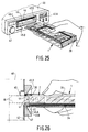
- This method may be of interest if after removal of the cassette from the holder the cassette is to be loaded into an apparatus 40, see Figs. 25 and 26. Loading is effected via a slot 41 in a front panel 42 of the apparatus.
- the apparatus shown may be, for example, a car-radio recorder but may alternatively be a portable recorder or radio-recorder or a stationary recorder or radio-recorder for home entertainment.
- the cassette is pushed out of the holder over some distance by means of the thumb and the part of the cassette which projects from the holder is inserted into the slot 41, after which the cassette is gripped by a loading mechanism (not shown) of the apparatus, which mechanism pulls the cassette completely out of the holder 1 into the apparatus.
- Loading mechanisms which automatically pull a cassette inserted partly in a slot further into an apparatus are widely known per se , for example from the afore-mentioned German Patent Application P4033095.5 and are therefore not described herein.
- An important feature in this connection is the presence of a gripping recess 39 at the front of the part of the cassette 2 which projects from the holder.
- the loading mechanism may comprise gripping means which are engageable with the gripping recess 39 to pull the cassette inward.
- Insertion of the cassette into the slot 41 is possible in two ways.
- Fig. 19 shows that the cassette can first be pushed out of the holder over some distance with the thumb of one hand, after which this part which projects from the holder is inserted into the slot.
- the holder is first positioned before the slot, after which the cassette is partly slid through the slot 41 in the apparatus by means of the thumb.
- this is not a basic difference. If it is difficult to position the holder correctly relative to the slot the first method would seem to be preferable.
- the holder 1 For the reinsertion of the cassette into the holder it is possible to use a method in accordance with which the holder 1 is positioned with its open side 25 before the front panel 42 at the location of the slot 41, after which the cassette is inserted, or at least partly inserted, into the holder by the apparatus via the slot 41. If the cassette is inserted only partly into the holder it can be inserted further by hand, for example by means of the thumb.
- Figures 25 and 26 show that it is possible to employ switching means, for example comprising a mechanical switch 43 with a push-button 44. The push-button 44 is actuated by the front wall 20 of the holder. As a result of this the loading mechanism of the apparatus ejects the cassette by means of an electric motor.
- a docking position defined by stop means by guide surfaces 45A, B, C and D around the slot 41, see Fig. 26.
- the stop means comprise a stop edge 46 situated around the slot 41. Both the guide surfaces 45A to 45D and the stop edge 46 belong to a docking means comprising a plastics frame 47 secured in the front panel 42 and formed with the slot 41.
- the guide surfaces 45A to 45D are inclined relative to the stop edge 46 and, as a result of this inclined orientation, they assist in guiding the holder from an inexact coarse position into the unambiguously defined docking position necessary for sliding the cassette into or out of the holder.
- the cassette is disposed exactly in line with the path 48 along which the cassette is moved by the loading mechanism of the apparatus. This is achieved in that the part of the stop edge 46 which is situated opposite the enclosure space 32 of the holder is wider than the part situated opposite the front wall 20. The receiving space of the holder is thus exactly aligned with the slot 41. This ensures an unobstructed insertion and removal of the cassette.
- the apparatus 40 in accordance with the invention shown in Figs. 25, 26 may be of an entirely different construction.
- the docking means may have a different shape and, if desired, they may be integrated with the front panel 42.
- the switching means may be electronic or electro-optical instead of mechanical.
- the docking means may be arranged inside the apparatus.
- the automatic means for transport of the cassette may cooperate with the cassette via the window 26.
- the holder with the cassette may be inserted into the apparatus as a unit, the cassette then being removed from the holder inside the apparatus.
- the invention has been described above on the basis of examples of holders provided with one or more magnetic-tape cassettes, the invention is not limited to its use in conjunction with such a recording medium.
- the holder in accordance with the invention can also be used for other suitable media, such as disc-shaped media with or without a cassette.
- suitable media such as disc-shaped media with or without a cassette.
- magneto-optical or any other record carriers may be stored in the holder.
Landscapes
- Packaging Of Annular Or Rod-Shaped Articles, Wearing Apparel, Cassettes, Or The Like (AREA)
- Automatic Tape Cassette Changers (AREA)
- Packaging For Recording Disks (AREA)
Applications Claiming Priority (2)
| Application Number | Priority Date | Filing Date | Title |
|---|---|---|---|
| NL9002653 | 1990-12-04 | ||
| NL9002653A NL9002653A (nl) | 1990-12-04 | 1990-12-04 | Houder voor een rechthoekige cassette. |
Publications (3)
| Publication Number | Publication Date |
|---|---|
| EP0493845A2 true EP0493845A2 (de) | 1992-07-08 |
| EP0493845A3 EP0493845A3 (en) | 1992-10-07 |
| EP0493845B1 EP0493845B1 (de) | 2000-02-23 |
Family
ID=19858082
Family Applications (1)
| Application Number | Title | Priority Date | Filing Date |
|---|---|---|---|
| EP91203104A Expired - Lifetime EP0493845B1 (de) | 1990-12-04 | 1991-11-27 | Gehäuse für eine rechteckige Kassette |
Country Status (9)
| Country | Link |
|---|---|
| EP (1) | EP0493845B1 (de) |
| JP (1) | JPH04279484A (de) |
| KR (1) | KR100269833B1 (de) |
| AT (1) | ATE189937T1 (de) |
| BR (1) | BR9105238A (de) |
| CA (1) | CA2056883A1 (de) |
| CS (1) | CS366691A3 (de) |
| DE (1) | DE69131999T2 (de) |
| NL (1) | NL9002653A (de) |
Cited By (12)
| Publication number | Priority date | Publication date | Assignee | Title |
|---|---|---|---|---|
| FR2705089A1 (fr) * | 1993-01-18 | 1994-11-18 | Basf Magnetics Gmbh | Récipient, notamment de forme parallélépipédique, pour au moins deux objets. |
| EP0791928A1 (de) * | 1996-02-23 | 1997-08-27 | Fuji Photo Film Co., Ltd. | Behälter für Plattenkassette |
| EP0809248A1 (de) * | 1996-05-24 | 1997-11-26 | Sony Corporation | Kassettenbehälter |
| WO1998019305A1 (en) * | 1996-10-26 | 1998-05-07 | Digisox Limited | A holder for a planar data storage medium |
| EP0854097A4 (de) * | 1996-07-08 | 1998-09-30 | Sony Corp | BEHäLTER ZUM AUFBEWAHREN VON KASSETTEN |
| EP0872841A1 (de) * | 1997-04-18 | 1998-10-21 | Sony Corporation | Behälter für Kassette |
| US5881871A (en) * | 1997-05-08 | 1999-03-16 | Tdk Corporation | Cartridge receiving casing |
| EP0971356A1 (de) * | 1998-07-09 | 2000-01-12 | Sony Corporation | Kassettenbehälter |
| EP0974969A3 (de) * | 1998-07-09 | 2001-04-11 | Sony Corporation | Kassettenbehälter |
| US6241093B1 (en) | 1998-07-09 | 2001-06-05 | Sony Corporation | Cassette accommodation case |
| US6328162B1 (en) | 1998-07-09 | 2001-12-11 | Sony Corporation | Cassette accomodation case |
| CN106882483A (zh) * | 2012-07-10 | 2017-06-23 | 洲际大品牌有限责任公司 | 包装组件及制造包装组件的方法 |
Family Cites Families (11)
| Publication number | Priority date | Publication date | Assignee | Title |
|---|---|---|---|---|
| US2617520A (en) * | 1948-07-23 | 1952-11-11 | Gillette Co | Blade dispensing magazine |
| GB1110215A (en) * | 1964-08-08 | 1968-04-18 | Marjorie Doreen Minchin | An improved razor blade dispenser |
| US3760937A (en) * | 1972-04-20 | 1973-09-25 | Wyngarden R Van | Interconnecting storage holder for tape cartridge |
| US3912077A (en) * | 1973-04-04 | 1975-10-14 | Witold Krynicki | Cassette holder |
| JPS609182Y2 (ja) * | 1981-06-18 | 1985-04-02 | アルファレコ−ド株式会社 | カセツトテ−プケ−スマガジン |
| JPS5826362A (ja) * | 1981-08-11 | 1983-02-16 | Matsushita Electric Ind Co Ltd | カセットテ−プロ−ディング装置 |
| JPS62170059A (ja) * | 1986-01-21 | 1987-07-27 | Mitsubishi Electric Corp | 回転ヘッド方式磁気記録または再生装置 |
| ES1007146Y (es) * | 1988-06-13 | 1989-08-01 | Lahora Sanchez Manuel | Estuche para peliculas de video. |
| DE4033095A1 (de) * | 1989-12-18 | 1991-06-20 | Philips Nv | Anordnung, bestehend aus einem magnetbandkassettengeraet mit einem laufwerk und lademechanismus fuer magnetbandkassetten und aus einer magnetbandkassette |
| AT394789B (de) * | 1990-10-11 | 1992-06-25 | Philips Nv | Kassette fuer einen aufzeichnungstraeger |
| DE69120494T2 (de) * | 1990-10-11 | 1997-01-23 | Philips Electronics Nv | Kassette mit Magnetband |
-
1990
- 1990-12-04 NL NL9002653A patent/NL9002653A/nl not_active Application Discontinuation
-
1991
- 1991-11-27 AT AT91203104T patent/ATE189937T1/de not_active IP Right Cessation
- 1991-11-27 EP EP91203104A patent/EP0493845B1/de not_active Expired - Lifetime
- 1991-11-27 DE DE69131999T patent/DE69131999T2/de not_active Expired - Fee Related
- 1991-11-29 JP JP3342068A patent/JPH04279484A/ja active Pending
- 1991-12-03 BR BR919105238A patent/BR9105238A/pt not_active Application Discontinuation
- 1991-12-03 CA CA002056883A patent/CA2056883A1/en not_active Abandoned
- 1991-12-03 CS CS913666A patent/CS366691A3/cs unknown
- 1991-12-03 KR KR1019910022014A patent/KR100269833B1/ko not_active Expired - Fee Related
Cited By (20)
| Publication number | Priority date | Publication date | Assignee | Title |
|---|---|---|---|---|
| FR2705089A1 (fr) * | 1993-01-18 | 1994-11-18 | Basf Magnetics Gmbh | Récipient, notamment de forme parallélépipédique, pour au moins deux objets. |
| EP0791928A1 (de) * | 1996-02-23 | 1997-08-27 | Fuji Photo Film Co., Ltd. | Behälter für Plattenkassette |
| EP1150298A1 (de) * | 1996-02-23 | 2001-10-31 | Fuji Photo Film Co., Ltd. | Behälter für Plattenkassette |
| US5782352A (en) * | 1996-02-23 | 1998-07-21 | Fuji Photo Film Co., Ltd. | Case for encasing disc cartridge therein |
| US5893453A (en) * | 1996-05-24 | 1999-04-13 | Sony Corporation | Cassette accommodation case |
| EP0809248A1 (de) * | 1996-05-24 | 1997-11-26 | Sony Corporation | Kassettenbehälter |
| US6286676B1 (en) | 1996-07-08 | 2001-09-11 | Sony Corporation | Cassette storage casing |
| EP0854097A4 (de) * | 1996-07-08 | 1998-09-30 | Sony Corp | BEHäLTER ZUM AUFBEWAHREN VON KASSETTEN |
| US6182825B1 (en) | 1996-10-26 | 2001-02-06 | Digisox Limited | Holder for a planar data storage medium |
| WO1998019305A1 (en) * | 1996-10-26 | 1998-05-07 | Digisox Limited | A holder for a planar data storage medium |
| EP0872841A1 (de) * | 1997-04-18 | 1998-10-21 | Sony Corporation | Behälter für Kassette |
| US5913423A (en) * | 1997-04-18 | 1999-06-22 | Sony Corporation | Cassette accommodation case |
| US5881871A (en) * | 1997-05-08 | 1999-03-16 | Tdk Corporation | Cartridge receiving casing |
| EP0971356A1 (de) * | 1998-07-09 | 2000-01-12 | Sony Corporation | Kassettenbehälter |
| US6260702B1 (en) | 1998-07-09 | 2001-07-17 | Sony Corporation | Cassette accommodation case |
| US6241093B1 (en) | 1998-07-09 | 2001-06-05 | Sony Corporation | Cassette accommodation case |
| EP0974969A3 (de) * | 1998-07-09 | 2001-04-11 | Sony Corporation | Kassettenbehälter |
| US6328162B1 (en) | 1998-07-09 | 2001-12-11 | Sony Corporation | Cassette accomodation case |
| CN106882483A (zh) * | 2012-07-10 | 2017-06-23 | 洲际大品牌有限责任公司 | 包装组件及制造包装组件的方法 |
| CN106882483B (zh) * | 2012-07-10 | 2020-07-31 | 洲际大品牌有限责任公司 | 包装组件及制造包装组件的方法 |
Also Published As
| Publication number | Publication date |
|---|---|
| JPH04279484A (ja) | 1992-10-05 |
| CS366691A3 (en) | 1992-06-17 |
| CA2056883A1 (en) | 1992-06-05 |
| ATE189937T1 (de) | 2000-03-15 |
| NL9002653A (nl) | 1992-07-01 |
| DE69131999D1 (de) | 2000-03-30 |
| EP0493845B1 (de) | 2000-02-23 |
| EP0493845A3 (en) | 1992-10-07 |
| KR920013400A (ko) | 1992-07-29 |
| KR100269833B1 (ko) | 2000-10-16 |
| BR9105238A (pt) | 1992-08-18 |
| DE69131999T2 (de) | 2000-10-05 |
Similar Documents
| Publication | Publication Date | Title |
|---|---|---|
| US5560481A (en) | Holder for a rectangular cassette | |
| US5558291A (en) | Drive for handling multiple size information storage media cartridges and cartridges therefor | |
| US4330161A (en) | Storage unit for tape cassettes | |
| GB2308719A (en) | Electronic apparatus with a pivoting, removable control panel | |
| JP3462318B2 (ja) | ディスクカートリッジ装置 | |
| EP0493845B1 (de) | Gehäuse für eine rechteckige Kassette | |
| US4660116A (en) | Video tape cassette with internal tape erasing means | |
| KR900010130Y1 (ko) | 테이프 카세트 | |
| WO2000031739A1 (en) | Magnetic tape cartridge | |
| JP3490554B2 (ja) | ディスクカートリッジ装置 | |
| WO1997022539A1 (fr) | Boitier pour cartouche de disque | |
| JP4157648B2 (ja) | 連動されるシャッタを有するディスクカートリッジ及びこれを駆動するディスク駆動装置 | |
| JP3491427B2 (ja) | ディスクカートリッジ | |
| US6052359A (en) | Disk cartridge having a dynamically stable supported member in a discrimination hole | |
| US5926351A (en) | Tape cartridge with irregular surface sections for reducing slippage between cartridge and gripping arms and debris production | |
| US5899330A (en) | Encasing mechanism for a cassette enclosing a magnetic record medium | |
| JP3106587B2 (ja) | ディスクケースおよび光ディスク装置 | |
| JPH0523511Y2 (de) | ||
| US5367421A (en) | Cartridge for a recording/reproducing medium having a transparent or semi-transparent cover member | |
| JP3011688B2 (ja) | カセットテープ | |
| JP3550857B2 (ja) | テープカートリッジ | |
| JP3506569B2 (ja) | 磁気ディスクカートリッジおよび磁気ディスク駆動装置 | |
| JPH0535507Y2 (de) | ||
| JPH08282765A (ja) | 収納ケース付きキャディ | |
| JP3482800B2 (ja) | ディスク収納体 |
Legal Events
| Date | Code | Title | Description |
|---|---|---|---|
| PUAI | Public reference made under article 153(3) epc to a published international application that has entered the european phase |
Free format text: ORIGINAL CODE: 0009012 |
|
| AK | Designated contracting states |
Kind code of ref document: A2 Designated state(s): AT BE CH DE DK ES FR GB GR IT LI LU NL SE |
|
| PUAL | Search report despatched |
Free format text: ORIGINAL CODE: 0009013 |
|
| AK | Designated contracting states |
Kind code of ref document: A3 Designated state(s): AT BE CH DE DK ES FR GB GR IT LI LU NL SE |
|
| 17P | Request for examination filed |
Effective date: 19930325 |
|
| 17Q | First examination report despatched |
Effective date: 19931004 |
|
| RAP3 | Party data changed (applicant data changed or rights of an application transferred) |
Owner name: KONINKLIJKE PHILIPS ELECTRONICS N.V. |
|
| GRAG | Despatch of communication of intention to grant |
Free format text: ORIGINAL CODE: EPIDOS AGRA |
|
| GRAG | Despatch of communication of intention to grant |
Free format text: ORIGINAL CODE: EPIDOS AGRA |
|
| GRAH | Despatch of communication of intention to grant a patent |
Free format text: ORIGINAL CODE: EPIDOS IGRA |
|
| GRAH | Despatch of communication of intention to grant a patent |
Free format text: ORIGINAL CODE: EPIDOS IGRA |
|
| GRAA | (expected) grant |
Free format text: ORIGINAL CODE: 0009210 |
|
| AK | Designated contracting states |
Kind code of ref document: B1 Designated state(s): AT BE CH DE DK ES FR GB GR IT LI LU NL SE |
|
| PG25 | Lapsed in a contracting state [announced via postgrant information from national office to epo] |
Ref country code: IT Free format text: LAPSE BECAUSE OF FAILURE TO SUBMIT A TRANSLATION OF THE DESCRIPTION OR TO PAY THE FEE WITHIN THE PRE;WARNING: LAPSES OF ITALIAN PATENTS WITH EFFECTIVE DATE BEFORE 2007 MAY HAVE OCCURRED AT ANY TIME BEFORE 2007. THE CORRECT EFFECTIVE DATE MAY BE DIFFERENT FROM THE ONE RECORDED.SCRIBED TIME-LIMIT Effective date: 20000223 Ref country code: NL Free format text: LAPSE BECAUSE OF FAILURE TO SUBMIT A TRANSLATION OF THE DESCRIPTION OR TO PAY THE FEE WITHIN THE PRESCRIBED TIME-LIMIT Effective date: 20000223 Ref country code: GR Free format text: LAPSE BECAUSE OF NON-PAYMENT OF DUE FEES Effective date: 20000223 Ref country code: ES Free format text: THE PATENT HAS BEEN ANNULLED BY A DECISION OF A NATIONAL AUTHORITY Effective date: 20000223 Ref country code: LI Free format text: LAPSE BECAUSE OF NON-PAYMENT OF DUE FEES Effective date: 20000223 Ref country code: AT Free format text: LAPSE BECAUSE OF FAILURE TO SUBMIT A TRANSLATION OF THE DESCRIPTION OR TO PAY THE FEE WITHIN THE PRESCRIBED TIME-LIMIT Effective date: 20000223 Ref country code: BE Free format text: LAPSE BECAUSE OF FAILURE TO SUBMIT A TRANSLATION OF THE DESCRIPTION OR TO PAY THE FEE WITHIN THE PRESCRIBED TIME-LIMIT Effective date: 20000223 Ref country code: CH Free format text: LAPSE BECAUSE OF NON-PAYMENT OF DUE FEES Effective date: 20000223 |
|
| REF | Corresponds to: |
Ref document number: 189937 Country of ref document: AT Date of ref document: 20000315 Kind code of ref document: T |
|
| REG | Reference to a national code |
Ref country code: CH Ref legal event code: EP |
|
| REF | Corresponds to: |
Ref document number: 69131999 Country of ref document: DE Date of ref document: 20000330 |
|
| PG25 | Lapsed in a contracting state [announced via postgrant information from national office to epo] |
Ref country code: SE Free format text: LAPSE BECAUSE OF FAILURE TO SUBMIT A TRANSLATION OF THE DESCRIPTION OR TO PAY THE FEE WITHIN THE PRESCRIBED TIME-LIMIT Effective date: 20000523 Ref country code: DK Free format text: LAPSE BECAUSE OF FAILURE TO SUBMIT A TRANSLATION OF THE DESCRIPTION OR TO PAY THE FEE WITHIN THE PRESCRIBED TIME-LIMIT Effective date: 20000523 |
|
| ET | Fr: translation filed | ||
| NLV1 | Nl: lapsed or annulled due to failure to fulfill the requirements of art. 29p and 29m of the patents act | ||
| REG | Reference to a national code |
Ref country code: CH Ref legal event code: PL |
|
| PGFP | Annual fee paid to national office [announced via postgrant information from national office to epo] |
Ref country code: FR Payment date: 20001121 Year of fee payment: 10 |
|
| PG25 | Lapsed in a contracting state [announced via postgrant information from national office to epo] |
Ref country code: LU Free format text: LAPSE BECAUSE OF NON-PAYMENT OF DUE FEES Effective date: 20001127 |
|
| PGFP | Annual fee paid to national office [announced via postgrant information from national office to epo] |
Ref country code: GB Payment date: 20001129 Year of fee payment: 10 |
|
| PLBE | No opposition filed within time limit |
Free format text: ORIGINAL CODE: 0009261 |
|
| STAA | Information on the status of an ep patent application or granted ep patent |
Free format text: STATUS: NO OPPOSITION FILED WITHIN TIME LIMIT |
|
| PGFP | Annual fee paid to national office [announced via postgrant information from national office to epo] |
Ref country code: DE Payment date: 20010118 Year of fee payment: 10 |
|
| 26N | No opposition filed | ||
| PG25 | Lapsed in a contracting state [announced via postgrant information from national office to epo] |
Ref country code: GB Free format text: LAPSE BECAUSE OF NON-PAYMENT OF DUE FEES Effective date: 20011127 |
|
| REG | Reference to a national code |
Ref country code: GB Ref legal event code: IF02 |
|
| PG25 | Lapsed in a contracting state [announced via postgrant information from national office to epo] |
Ref country code: DE Free format text: LAPSE BECAUSE OF NON-PAYMENT OF DUE FEES Effective date: 20020702 |
|
| GBPC | Gb: european patent ceased through non-payment of renewal fee |
Effective date: 20011127 |
|
| PG25 | Lapsed in a contracting state [announced via postgrant information from national office to epo] |
Ref country code: FR Free format text: LAPSE BECAUSE OF NON-PAYMENT OF DUE FEES Effective date: 20020730 |
|
| REG | Reference to a national code |
Ref country code: FR Ref legal event code: ST |
|
| REG | Reference to a national code |
Ref country code: FR Ref legal event code: ST |