EP0493880A2 - Bandführungsrolle für Bildbandaufzeichnungsgerät - Google Patents
Bandführungsrolle für Bildbandaufzeichnungsgerät Download PDFInfo
- Publication number
- EP0493880A2 EP0493880A2 EP91310598A EP91310598A EP0493880A2 EP 0493880 A2 EP0493880 A2 EP 0493880A2 EP 91310598 A EP91310598 A EP 91310598A EP 91310598 A EP91310598 A EP 91310598A EP 0493880 A2 EP0493880 A2 EP 0493880A2
- Authority
- EP
- European Patent Office
- Prior art keywords
- tape
- roller
- flange
- guide roller
- height
- Prior art date
- Legal status (The legal status is an assumption and is not a legal conclusion. Google has not performed a legal analysis and makes no representation as to the accuracy of the status listed.)
- Withdrawn
Links
Images

Classifications
-
- G—PHYSICS
- G11—INFORMATION STORAGE
- G11B—INFORMATION STORAGE BASED ON RELATIVE MOVEMENT BETWEEN RECORD CARRIER AND TRANSDUCER
- G11B15/00—Driving, starting or stopping record carriers of filamentary or web form; Driving both such record carriers and heads; Guiding such record carriers or containers therefor; Control thereof; Control of operating function
- G11B15/60—Guiding record carrier
- G11B15/605—Guiding record carrier without displacing the guiding means
-
- G—PHYSICS
- G11—INFORMATION STORAGE
- G11B—INFORMATION STORAGE BASED ON RELATIVE MOVEMENT BETWEEN RECORD CARRIER AND TRANSDUCER
- G11B15/00—Driving, starting or stopping record carriers of filamentary or web form; Driving both such record carriers and heads; Guiding such record carriers or containers therefor; Control thereof; Control of operating function
- G11B15/60—Guiding record carrier
- G11B15/61—Guiding record carrier on drum, e.g. drum containing rotating heads
Definitions
- the present invention generally relates to tape guide rollers and, more particularly, is directed to a tape guide roller for use in a tape transport portion of a tape recording and/or reproducing apparatus and to a tape transport mechanism, e.g. of such an apparatus.
- FIG. 1 of the accompanying drawings schematically illustrates an example of a tape transport system of a tape recording and reproducing apparatus, e.g. an 8mm video tape recorder (8mm VTR).
- a tape transport system of a tape recording and reproducing apparatus e.g. an 8mm video tape recorder (8mm VTR).
- reference numeral 1 depicts a tape cassette and reference numeral 2 a tape (magnetic tape) accommodated within the tape cassette 1.
- the tape 2 is withdrawn from the tape cassette 1 and wrapped around a magnetic head drum 3, thereby transported in this state.
- Reference number 4 depicts a tension regulator, 5 a capstan and 6 a pinch roller.
- Tape guide rollers 7 are disposed at both sides of the magnetic head drum 3 and the height of the tape 2 relative to the magnetic head drum 3 is regulated by these tape guide rollers 7.
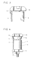
- FIG. 2 of the accompanying drawings shows an arrangement of this kind of conventional tape guide roller 7 which is composed of a roller 9 pivotally supported to a roller shaft 8, and upper and lower flanges 10 and 11 attached to the roller shaft 8 above and below the roller 9.
- the tape guide roller 7 is secured to a base portion (not shown) of a tape recording and reproducing transport mechanism by means of a screw portion 12.
- the tape 2 is transported while in rotatable contact with the roller 9, and the height thereof is regulated by the upper and lower flanges 10 and 11. More specifically, in the illustrative example of Figure 2, a lower end surface of the upper flange 10 serves as a tape regulating end face 13 and the height of the tape 2 is regulated by the lateral edge of the tape 2 abutting the tape regulating end face 13.
- the tape guide roller 7 thus arranged regulates the height of the tape 2 at the tape regulating end face 13 of the upper flange 10 so that, if the tape is thin or weak, it will be easily buckled at its tape edge by a tape regulating force applied thereto from the tape regulating end face 13 of the upper flange 10 as shown in figure 3. Accordingly, it is to be noted that this conventional tape guide roller 7 is not adequately designed to prevent the tape from being damaged, broken or crinkled. Furthermore, in order to keep the stability of the tape transport system without tape damage or the like, the tape path must be adjusted with high accuracy, which is very difficult in actual practice, and the assembly parts must be produced with high accuracy.
- An additional object of the present invention is to provide a tape guide roller far use in a tape recording and reproducing apparatus such as an 8mm VTR or the like.
- a tape guide roller provided in a tape transport portion of a tape recording and reproducing apparatus, comprising:
- the invention also provides a tape transport mechanism for a recording and/or reproducing apparatus such as an 8mm VTR or the like incorporating the roller of the invention.
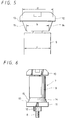
- tape transport portion 14 is unitarily formed with the lower surface of the upper flange 10 so as to permit the transport of the tape 2. It will be apparent that the portion 14 does not rotate, as it is unitary with the shaft about which the roller 9 rotates.
- a circumferential surface of the tape transport 14, i.e., the surface opposing the inner surface of the tape 2 is formed as a tapered surface 15, the outer diameter of which decreases in direction towards the roller 9.
- the maximum diameter a of the tape transport portion 14 is larger than an outer diameter c of the roller 9 and the minimum diameter b thereof is smaller than the outer diameter c of the roller 9.
- the minimum diameter b of the tape transport portion 14 might be equal to the outer diameter c of the roller 9.
- the tape transport portion 14 having the tapered surface 15 is unitarily formed with the upper flange 10, the height (length) of the roller 9 can be reduced accordingly, as compared with the example of the prior art.
- the rest of elements and parts of this embodiment is the same as that of the example of the prior art.
- the tape 2 is transported while in rotatable contact with the circumferential surface of the roller 9, and the height of the tape 2 is regulated by the cooperation of the tape regulating end face 13 of the upper flange 10 and the tapered surface 15 of the tape transport portion 14. That is, the tape edge of the tape 2 slidably contacts with the tape regulating end face 13 of the upper flange 10 and also slidably contacts with the tapered surface 15 of the tape transport portion 14 to generate a regulating force which acts downwardly on the tape 2 (force which regulates the upward movement of the tape 2), thereby regulating the height of the tape 2.
- the tape 2 can be prevented from being buckled unlike the prior art.
- the height of the tape 2 is regulated only by the tape regulating end face 13 of the upper flange 10
- the height regulating force for regulating the height of the tape 2 is generated by the cooperation of both the tape regulating end face 13 of the upper flange 10 and the tapered surface 15 of the tape transport portion 14, which the tape contacts first if it rides up the roller 9, whereby the height of the tape 2 can be regulated without applying an excessive force to the tape 2. Accordingly, unlike the prior art, the tape 2 can be prevented from being buckled and the tape guide roller of this embodiment becomes less prone to damaging the tape.
- the inventor has made the tape guide roller of this embodiment and mounted it on the mechanical deck of the 8mm VTR for test.
- tape tensions at which the tape will be damaged were measured during the tape running.
- the measured results demonstrate that the roller permits the tape tension at the onset of tape damage to be 3 to 3.5 times that of the prior art. That is, the tape guide roller of this embodiment enables a tension of 3 to 3.5 times that of the prior art before damage of the tape occurs.
- the tape guide roller of the present invention becomes resistant to the tape damage as described above, the stability of the tape transport system can be maintained with ease, and the number of steps necessary to adjust and check the tape path can be reduced considerably. Also, the accuracy of the assembly parts need not be as great as that of the prior art.
- the present invention is not limited thereto and such a variant is also possible that the height of the tape 2 might be regulated on the lower flange 11 side.
- an upper end face of the lower flange 11 is served as the tape regulating end face 13 and the lower flange 11 is unitarily formed with the tape transport portion 14 whose tapered surface 15 is reduced in diameter at the roller 9 side.
- Both variants may be used in the same tape transport paths to give regulation of the tape height in both senses. It will be apparent that there could be the tape regulating surfaces at both ends of the roller, though that would require the assembly to be fabricated in a manner which would permit the roller 9 to be mounted on the central region of the shaft.
- the tape guide roller of the present invention is constructed so as to generate the tape height regulating force by the cooperation of both the tape regulating end face of the flange and the tapered surface of the tape transport portion, the tape height can be regulated without applying an excessive force to the tape, thereby preventing the tape from being buckled at its end edge unlike the prior art.
- the tape guide roller of the invention becomes resistant to the tape damage. Also, the stability of the tape transport system can be maintained with ease.
Landscapes
- Registering, Tensioning, Guiding Webs, And Rollers Therefor (AREA)
Applications Claiming Priority (2)
| Application Number | Priority Date | Filing Date | Title |
|---|---|---|---|
| JP414951/90 | 1990-12-27 | ||
| JP2414951A JPH04229447A (ja) | 1990-12-27 | 1990-12-27 | ローラーテープガイド |
Publications (2)
| Publication Number | Publication Date |
|---|---|
| EP0493880A2 true EP0493880A2 (de) | 1992-07-08 |
| EP0493880A3 EP0493880A3 (en) | 1992-08-05 |
Family
ID=18523370
Family Applications (1)
| Application Number | Title | Priority Date | Filing Date |
|---|---|---|---|
| EP19910310598 Withdrawn EP0493880A3 (en) | 1990-12-27 | 1991-11-18 | Tape guide roller for use in video tape recorder |
Country Status (3)
| Country | Link |
|---|---|
| US (1) | US5501386A (de) |
| EP (1) | EP0493880A3 (de) |
| JP (1) | JPH04229447A (de) |
Cited By (5)
| Publication number | Priority date | Publication date | Assignee | Title |
|---|---|---|---|---|
| GB2279489A (en) * | 1993-06-30 | 1995-01-04 | M4 Data Ltd | A tape guide roller with fixed edge guides |
| EP0668587A2 (de) | 1994-02-18 | 1995-08-23 | Philips Patentverwaltung GmbH | Aufzeichnungs- und/oder Wiedergabegerät |
| EP0712124A3 (de) * | 1994-11-09 | 1997-01-22 | Sony Corp | Bandlademechanismus |
| GB2307772A (en) * | 1995-11-28 | 1997-06-04 | Daewoo Electronics Co Ltd | Tape guide post structure for use in a video cassette recorder |
| NL1014096C2 (nl) * | 2000-01-17 | 2001-07-18 | Onstream B V | Spoelhouder. |
Families Citing this family (16)
| Publication number | Priority date | Publication date | Assignee | Title |
|---|---|---|---|---|
| KR0153996B1 (ko) * | 1995-06-30 | 1998-12-15 | 배순훈 | 테이프 레코더의 테이프 주행 가이드 장치 |
| JP2824040B2 (ja) * | 1996-01-23 | 1998-11-11 | 株式会社フジパーツ | 磁気テープ用ガイドローラ |
| US5940254A (en) * | 1997-06-26 | 1999-08-17 | Sony Corporation | Inverted crowning of data cartridge corner rolls |
| US6267325B1 (en) * | 1999-03-25 | 2001-07-31 | Quantum Corporation | Tape support |
| US6336608B1 (en) | 2000-02-29 | 2002-01-08 | James Robert Cope | Flexible web roller guide assembly with an integral centrifugal pump capability to provide a hydrostatic air bearing function to the roller guides outside supporting surface |
| US6352188B1 (en) * | 2000-08-03 | 2002-03-05 | Eastman Kodak Company | Edge drive for photosensitive media |
| JP2002308489A (ja) * | 2001-04-16 | 2002-10-23 | Fuji Photo Film Co Ltd | 磁気テープの製造方法 |
| US6676070B2 (en) | 2001-08-03 | 2004-01-13 | Quantum Corporation | Backward compatible tape support |
| US6634535B2 (en) * | 2001-10-02 | 2003-10-21 | Mitsumi Electric Co., Ltd. | Roller shaft |
| US6886766B1 (en) | 2002-01-15 | 2005-05-03 | Seagate Removable Storage Solutions Llc | Tape guiding assembly for a tape drive |
| US7175129B2 (en) * | 2004-07-23 | 2007-02-13 | Tandberg Storage Asa | Drive for magnetic tape adjustable for use with tapes of different widths |
| US7306181B1 (en) * | 2004-12-30 | 2007-12-11 | Storage Technology Corporation | Guide for directing tape media along tape path with reduced contact between guide and tape edge |
| US7172149B1 (en) | 2005-08-22 | 2007-02-06 | Tandberg Storage Asa | Long tape path guide system and method |
| US7349181B2 (en) * | 2005-09-21 | 2008-03-25 | International Business Machines Corporation | Rotatable tape guide with tapered flanges |
| US20100128379A1 (en) * | 2008-11-24 | 2010-05-27 | Quantum Corporation | Guide assembly for reducing lateral tape motion in a tape drive |
| JP5803253B2 (ja) * | 2011-05-10 | 2015-11-04 | 住友電装株式会社 | キャプスタン装置 |
Family Cites Families (11)
| Publication number | Priority date | Publication date | Assignee | Title |
|---|---|---|---|---|
| NL290635A (de) * | 1962-06-18 | |||
| US3295780A (en) * | 1963-11-29 | 1967-01-03 | Hewlett Packard Co | Tape recording and reproducing apparatus |
| US3276651A (en) * | 1964-04-27 | 1966-10-04 | Ampex | Roller guide for web transport mechanisms |
| US3768717A (en) * | 1972-02-07 | 1973-10-30 | Echo Science Corp | Spring biased tape guide with means for distributing tape edge forces along the tape length |
| US4017897A (en) * | 1975-09-17 | 1977-04-12 | Eastman Kodak Company | Magnetic tape guide having a tapered roller and an adjustable contoured edge |
| US4114751A (en) * | 1976-10-22 | 1978-09-19 | Teletype Corporation | Printing machine with automatic off-center crown roller ribbon-wear compensation |
| US4337885A (en) * | 1980-06-10 | 1982-07-06 | Stahler Alfred F | Apparatus for guiding tape |
| DE3127340C2 (de) * | 1980-07-17 | 1985-01-31 | Hitachi, Ltd., Tokio/Tokyo | Führungsrolle für ein Bandbewegungssystem eines magnetischen Aufnahme- und Wiedergabegeräts |
| US4336900A (en) * | 1980-07-17 | 1982-06-29 | Bell & Howell Company | Adjustable tape guiding method and apparatus |
| KR880000661Y1 (ko) * | 1985-06-26 | 1988-03-14 | 주식회사금성사 | 비디오 테이프 레코오더의 테이프 가이드 로울러 |
| US5160078A (en) * | 1991-02-12 | 1992-11-03 | Storage Technology Corporation | Rotating compliant tape guide |
-
1990
- 1990-12-27 JP JP2414951A patent/JPH04229447A/ja active Pending
-
1991
- 1991-11-18 EP EP19910310598 patent/EP0493880A3/en not_active Withdrawn
-
1995
- 1995-06-05 US US08/462,569 patent/US5501386A/en not_active Expired - Fee Related
Cited By (11)
| Publication number | Priority date | Publication date | Assignee | Title |
|---|---|---|---|---|
| GB2279489A (en) * | 1993-06-30 | 1995-01-04 | M4 Data Ltd | A tape guide roller with fixed edge guides |
| GB2279489B (en) * | 1993-06-30 | 1997-04-02 | M4 Data Ltd | Tape drive machines |
| EP0668587A2 (de) | 1994-02-18 | 1995-08-23 | Philips Patentverwaltung GmbH | Aufzeichnungs- und/oder Wiedergabegerät |
| EP0668587A3 (de) * | 1994-02-18 | 1996-02-28 | Philips Patentverwaltung | Aufzeichnungs- und/oder Wiedergabegerät. |
| EP0712124A3 (de) * | 1994-11-09 | 1997-01-22 | Sony Corp | Bandlademechanismus |
| US5808827A (en) * | 1994-11-09 | 1998-09-15 | Sony Corporation | Tape loading mechanism |
| GB2307772A (en) * | 1995-11-28 | 1997-06-04 | Daewoo Electronics Co Ltd | Tape guide post structure for use in a video cassette recorder |
| US5769356A (en) * | 1995-11-28 | 1998-06-23 | Daewoo Electronics Co., Ltd. | Tape guide structure for use in a video cassette recorder |
| GB2307772B (en) * | 1995-11-28 | 1999-11-03 | Daewoo Electronics Company Lim | Tape guide structure for use in a video cassette recorder |
| NL1014096C2 (nl) * | 2000-01-17 | 2001-07-18 | Onstream B V | Spoelhouder. |
| WO2001054129A1 (en) * | 2000-01-17 | 2001-07-26 | Onstream B.V. | Tape cartridge |
Also Published As
| Publication number | Publication date |
|---|---|
| JPH04229447A (ja) | 1992-08-18 |
| US5501386A (en) | 1996-03-26 |
| EP0493880A3 (en) | 1992-08-05 |
Similar Documents
| Publication | Publication Date | Title |
|---|---|---|
| EP0493880A2 (de) | Bandführungsrolle für Bildbandaufzeichnungsgerät | |
| US6963467B2 (en) | Method and apparatus for compensating for media shift due to tape guide | |
| US5407117A (en) | Tape guide for a magnetic recording and/or reproducing apparatus | |
| KR930001876B1 (ko) | 비디오 레코더의 테이프 주행장치 | |
| KR940006386B1 (ko) | 자기 기록 재생장치의 테이프 텐션 제어장치 | |
| EP0042475A1 (de) | Wickelkern für Bandrollen | |
| US5808827A (en) | Tape loading mechanism | |
| US4646186A (en) | Cassette tape recorder with plural tape guide structure | |
| US5469319A (en) | Magnetic tape cassette having tape edge regulating members | |
| JPH04129054A (ja) | テープ走行装置 | |
| US5784229A (en) | Driving apparatus in which a distance between a first flange and a second flange of a tape guide is larger than a distance between a first flange and a second flange of a take-up reel | |
| US5117322A (en) | Tape guide mechanism for helical scan recording/reproduction apparatus | |
| US4012792A (en) | Magnetic head drum configuration having a friction reducing helical step | |
| US3468490A (en) | Continuous loop recording tape cartridge | |
| JP3105221B2 (ja) | 磁気テープレコーダ | |
| CA1325057C (en) | Magnetic recording and reproducing apparatus with single inclining post | |
| KR900000252Y1 (ko) | 테이프 카세트 | |
| EP0386837A1 (de) | Bandgerät | |
| JP2749177B2 (ja) | 記録再生装置 | |
| JP3118951B2 (ja) | テープガイドおよび磁気記録再生装置 | |
| JPH0981996A (ja) | 記録又は再生装置 | |
| JPH05151661A (ja) | 磁気記録再生装置 | |
| JPH06282909A (ja) | ガイドローラ | |
| JPH04321966A (ja) | テープ案内機構 | |
| JPH03259448A (ja) | 磁気記録再生装置のテープ案内体 |
Legal Events
| Date | Code | Title | Description |
|---|---|---|---|
| PUAI | Public reference made under article 153(3) epc to a published international application that has entered the european phase |
Free format text: ORIGINAL CODE: 0009012 |
|
| PUAL | Search report despatched |
Free format text: ORIGINAL CODE: 0009013 |
|
| AK | Designated contracting states |
Kind code of ref document: A2 Designated state(s): DE FR GB |
|
| AK | Designated contracting states |
Kind code of ref document: A3 Designated state(s): DE FR GB |
|
| 17P | Request for examination filed |
Effective date: 19930108 |
|
| 17Q | First examination report despatched |
Effective date: 19950315 |
|
| STAA | Information on the status of an ep patent application or granted ep patent |
Free format text: STATUS: THE APPLICATION IS DEEMED TO BE WITHDRAWN |
|
| 18D | Application deemed to be withdrawn |
Effective date: 19950926 |