EP0494006A1 - Turbopumpe mit einer durch Bypassströmung angetriebenen Überdruckpumpe - Google Patents
Turbopumpe mit einer durch Bypassströmung angetriebenen Überdruckpumpe Download PDFInfo
- Publication number
- EP0494006A1 EP0494006A1 EP91403485A EP91403485A EP0494006A1 EP 0494006 A1 EP0494006 A1 EP 0494006A1 EP 91403485 A EP91403485 A EP 91403485A EP 91403485 A EP91403485 A EP 91403485A EP 0494006 A1 EP0494006 A1 EP 0494006A1
- Authority
- EP
- European Patent Office
- Prior art keywords
- turbopump
- low pressure
- high pressure
- impeller
- fluid
- Prior art date
- Legal status (The legal status is an assumption and is not a legal conclusion. Google has not performed a legal analysis and makes no representation as to the accuracy of the status listed.)
- Granted
Links
- 239000012530 fluid Substances 0.000 claims abstract description 78
- 230000002706 hydrostatic effect Effects 0.000 claims description 9
- 238000007789 sealing Methods 0.000 claims description 8
- 210000003027 ear inner Anatomy 0.000 claims description 6
- 238000013016 damping Methods 0.000 claims description 3
- 239000011888 foil Substances 0.000 claims description 3
- 230000003014 reinforcing effect Effects 0.000 claims description 2
- 238000005266 casting Methods 0.000 claims 2
- 239000007789 gas Substances 0.000 description 31
- 238000010586 diagram Methods 0.000 description 11
- 239000007788 liquid Substances 0.000 description 9
- 238000003304 gavage Methods 0.000 description 6
- 235000021183 entrée Nutrition 0.000 description 3
- 230000004907 flux Effects 0.000 description 3
- 238000005461 lubrication Methods 0.000 description 3
- 210000000056 organ Anatomy 0.000 description 3
- 238000011144 upstream manufacturing Methods 0.000 description 3
- 230000010354 integration Effects 0.000 description 2
- 238000007726 management method Methods 0.000 description 2
- 239000003380 propellant Substances 0.000 description 2
- MYMOFIZGZYHOMD-UHFFFAOYSA-N Dioxygen Chemical compound O=O MYMOFIZGZYHOMD-UHFFFAOYSA-N 0.000 description 1
- 239000000470 constituent Substances 0.000 description 1
- 230000001419 dependent effect Effects 0.000 description 1
- 230000001627 detrimental effect Effects 0.000 description 1
- 238000009434 installation Methods 0.000 description 1
- 238000004519 manufacturing process Methods 0.000 description 1
- 238000005457 optimization Methods 0.000 description 1
- 230000001737 promoting effect Effects 0.000 description 1
- 230000035945 sensitivity Effects 0.000 description 1
- 238000004904 shortening Methods 0.000 description 1
- 238000009987 spinning Methods 0.000 description 1
Images




Classifications
-
- F—MECHANICAL ENGINEERING; LIGHTING; HEATING; WEAPONS; BLASTING
- F04—POSITIVE - DISPLACEMENT MACHINES FOR LIQUIDS; PUMPS FOR LIQUIDS OR ELASTIC FLUIDS
- F04D—NON-POSITIVE-DISPLACEMENT PUMPS
- F04D13/00—Pumping installations or systems
- F04D13/02—Units comprising pumps and their driving means
- F04D13/04—Units comprising pumps and their driving means the pump being fluid driven
- F04D13/043—Units comprising pumps and their driving means the pump being fluid driven the pump wheel carrying the fluid driving means
-
- F—MECHANICAL ENGINEERING; LIGHTING; HEATING; WEAPONS; BLASTING
- F02—COMBUSTION ENGINES; HOT-GAS OR COMBUSTION-PRODUCT ENGINE PLANTS
- F02K—JET-PROPULSION PLANTS
- F02K9/00—Rocket-engine plants, i.e. plants carrying both fuel and oxidant therefor; Control thereof
- F02K9/42—Rocket-engine plants, i.e. plants carrying both fuel and oxidant therefor; Control thereof using liquid or gaseous propellants
- F02K9/44—Feeding propellants
- F02K9/46—Feeding propellants using pumps
- F02K9/48—Feeding propellants using pumps driven by a gas turbine fed by propellant combustion gases or fed by vaporized propellants or other gases
-
- F—MECHANICAL ENGINEERING; LIGHTING; HEATING; WEAPONS; BLASTING
- F04—POSITIVE - DISPLACEMENT MACHINES FOR LIQUIDS; PUMPS FOR LIQUIDS OR ELASTIC FLUIDS
- F04D—NON-POSITIVE-DISPLACEMENT PUMPS
- F04D1/00—Radial-flow pumps, e.g. centrifugal pumps; Helico-centrifugal pumps
- F04D1/02—Radial-flow pumps, e.g. centrifugal pumps; Helico-centrifugal pumps having non-centrifugal stages, e.g. centripetal
- F04D1/025—Comprising axial and radial stages
-
- F—MECHANICAL ENGINEERING; LIGHTING; HEATING; WEAPONS; BLASTING
- F04—POSITIVE - DISPLACEMENT MACHINES FOR LIQUIDS; PUMPS FOR LIQUIDS OR ELASTIC FLUIDS
- F04D—NON-POSITIVE-DISPLACEMENT PUMPS
- F04D9/00—Priming; Preventing vapour lock
- F04D9/04—Priming; Preventing vapour lock using priming pumps; using booster pumps to prevent vapour-lock
Definitions
- the present invention relates to a turbopump with integrated booster in bypass flow, for pressurizing a fluid.
- Turbopumps are used in various fields and in particular in the space field for the pressurization of propellants.
- a traditional drive mode of a low-pressure booster pump 3 shown diagrammatically in FIG. 2A is constituted by a bypass circuit.
- part 7 of the HP fluid conveyed by the high pressure pump 1 is recirculated from the output of the HP pump 1 to the low pressure hydraulic turbine 4 which is used to drive the BP booster pump 3.
- the fluid BP 5 introduced into the pump BP 3 has an average pressure (MP) at the outlet thereof so that the current of medium pressure fluid 6 applied to the inlet of the HP pump 1 makes it possible to avoid any cavitation at the level of the HP pump 1 even if it has a high rotation speed.
- MP average pressure
- the HP fluid 7 recirculated to the hydraulic turbine 4 driving the shaft 42 of the BP pump 3 constitutes only a relatively small fraction of the useful HP flow current 8.
- the shaft 41 of the HP pump 1 is itself conventionally driven by a gas turbine 2 having an inlet 9 for HP gas and an outlet 10 for LP gas.
- FIG. 2B shows a particular example of embodiment of a pump, such as that illustrated diagrammatically in FIG. 2A, proposed in a NASA monograph entitled "Turbopump systems for liquid rocket engines SP-8107, pp. 53-55.
- FIG. 2B thus shows a BP booster pump 3 driven by a hydraulic turbine 4 supplied from a fraction 7 of the HP fluid 8 coming from the HP pump 1, itself driven from a gas turbine not shown on Figure 2B.
- FIGS. 3A to 3D show systems associating a BP 13 booster pump with an HP 11 pump, according to a cascade circuit.
- FIG. 3A presents the schematic diagram of such a system, in which all the flow of fluid 17 leaving the HP pump 11 actuates, with a slight expansion, the hydraulic turbine BP 14 which drives the pump BP 42 through the pump booster 13 receiving the inlet BP fluid stream 15 to return to the inlet of the impeller HP of the HP pump 11 a fluid stream 16 at medium pressure.
- the shaft 41 of the HP pump 11 delivers an output current 18 and is conventionally driven by a gas turbine 12 having an inlet 19 for HP gas and an outlet 20 for BP gas.
- FIGS. 3B and 3C show an example of application of the circuit of FIG. 3A in the case of a booster pump 13 of low power.
- Figure 3B shows the arrangement of the different constituents of the system of FIG. 3A, with the exception of the gas turbine 12 which is not shown and
- FIG. 3C shows, in a simplified manner, the relative arrangements, in the arrangement of FIG. 3B, of the shaft main drive 41 driven by the gas turbine 12 and the hydraulically driven shaft 42 with its bearings 43, 44 for support relative to the frame.
- FIG. 3C shows symbolically the rotating elements integral with the shafts 41 and 42, that is to say the rotating elements of the hydraulic turbine 14 and the BP pump 13 which are integral with the secondary shaft BP 42 and the rotating elements of the HP pump 11, which are integral with the main HP 41 shaft.
- FIG. 3D illustrates another particular embodiment of a circuit involving a cascade cycle, such as that of FIG. 3A, which has been described in a work by O.E.BALJE, entitled “Turbomachines", p. 429, published by Wiley Editions in 1981.
- the hydraulic turbine 14 consists of a rotating diffuser placed downstream of the HP impeller of the HP pump 11 and secured to a BP inductor 13 which plays a similar function that the booster pump 13 of FIG. 3A, and is placed upstream of the impeller of the HP pump 11.
- Figure 4 shows the block diagram of a turbopump system with BP booster pump in which a BP booster pump 23 is secured to a shaft 42 driven by a gas turbine 24 supplied from a gas stream main 22 for driving the HP pump 21.
- the reference 29 designates the stream of HP gas applied to the main gas turbine 22 while the reference 32 designates the stream of LP gas from the gas turbine auxiliary 24.
- References 25, 26 and 28 themselves designate respectively the liquid stream BP at the input of the booster pump 23, the liquid stream MP coming from the booster pump 23 and applied to the HP pump 21 and the current of HP liquid delivered by the HP pump 21.
- a system such as that of FIG. 4 is disadvantaged by the problems of differential expansion between the cold parts on the pump side and the hot parts on the turbine side and by the problems of sealing between liquid circuits and gas circuits, which are inherent in this cycle.
- a cycle such as that of FIG. 4 is moreover prohibited in the case of chemically very active fluids such as liquid oxygen.
- the present invention aims to remedy the drawbacks of the systems of the prior art and to allow the use of a low pressure booster pump in association with a turbopump, with the aim of eliminating or limiting the phenomenon of cavitation in the part of the high pressure pump at high rotational speeds, achieving a high compactness of the assembly while maintaining a high level of performance.
- a turbopump with integrated booster in bypass flow for pressurizing a fluid, characterized in that it comprises, inside the same casing, a main shaft driven by a turbine, a shaft secondary coaxial with the main shaft, at least one low pressure inductor mounted in the casing on the secondary shaft in the vicinity of a low pressure fluid inlet, at least one low pressure impeller mounted on the secondary shaft downstream of the '' low pressure inductor, a low pressure rectifier secured to the casing and disposed downstream of the low pressure impeller, to bring the flow of medium pressure fluid parallel to the axis of the turbopump, a return channel to divert 180 ° the medium pressure fluid flow from the rectifier and bring this flow parallel to the axis of the turbopump to a high pressure impeller mounted on the main shaft inside the secondary shaft so as to send the whole of the high pressure centrifugal flow formed by the high pressure impeller towards the inside of fixed hollow blades forming part of said rectifier in the direction of a delivery channel, integral with
- the turbopump also preferably comprises a high pressure inductor mounted on the main shaft between the return channel and the high pressure impeller.
- the particularly compact architecture of the turbopump according to the invention with integration in the turbomachine, of a rotary booster constituted by a booster impeller driven by a small fraction of the pressurized fluid and intended to increase the pressure of the fluid as it enters the main pump leads to a significant reduction in the total mass of the machine and its bulk while reducing the number of parts required without increasing the difficulties of production of parts.
- the overall design is simplified due to the absence of special circuits for recovering and managing liquid or gas leaks, and it is possible to use a discharge channel which has a simpler form than that of a volute and can even be a torus which reduces the cost.
- the constitution of the mechanical energy exchanger in the form of a turbine-impeller with hollow blades contributes to the compactness of the whole machine by the combination of two functions played by separate organs in the realization of the prior art.
- the interior of the hollow blades which is traversed by a part of the flow pressurized by the main pump, plays the role of turbine for the low pressure pump while the exterior of these blades plays the role of spinning wheel of the booster pump.
- the low pressure booster pump defines a current of medium pressure fluid essentially parallel to the axis of the turbopump while the high pressure pump is arranged so that the high pressure impeller delivers the high pressure fluid, towards the discharge channel in a plane approximately perpendicular to the axis of the turbopump.
- the bypass channel itself originates in the discharge channel in such a way that the flow of derived liquid which constitutes a low flow rate, can penetrate from the outside into the hollow curved blades of the low pressure impeller, in a centripetal manner.
- This embodiment is particularly advantageous from a functional point of view and lends itself to easy realization, insofar as only a low flow rate, under a relatively large pressure difference, passes through the hollow curved blades of the low pressure impeller.
- the dimensioning of the movable hollow blades is all the easier to achieve when the flow rate which must pass through these hollow blades is low.
- the main shaft carries a rotor secured to the high pressure impeller which defines with the secondary shaft a space for receiving the derivative flow having passed through the curved hollow blades and returns this derivative flow to the arrival of low pressure fluid through bearings of support of the secondary shaft with respect to the main shaft and the outlet orifices provided in the secondary shaft.
- the main shaft driven at high speed by the turbine is mounted relative to the casing on the one hand using a hydrostatic bearing disposed between the low pressure rectifier and the high pressure inductor or the high pressure impeller and on the other hand, a bearing suitable for high speeds mounted in the rear bottom of the return channel.
- the secondary shaft is mounted on the main shaft by means of a roller bearing and bearings marbles.
- This arrangement with four bearings makes it possible to obtain a high speed of rotation for the main HP shaft and the free rotation of the low pressure assembly driven by the hydraulic turbine.
- the bearings placed between the BP pump and the HP pump rotate at a low relative speed which corresponds to the difference between the rotational speeds of the main HP shaft and the secondary BP shaft. In this way, the bearings are used little and their service life is increased.
- said bearing mounted in the rear bottom of the return channel is a ball bearing lubricated and cooled by a low flow of medium pressure fluid taken at the outlet of the low pressure rectifier by a recirculation channel of short length provided in the wall of the return channel.
- said bearing mounted in the rear bottom of the return channel is a fluid or foil bearing supplied by a low flow of medium pressure fluid taken at the outlet of the low pressure rectifier by a short recirculation channel. formed in the wall of the return channel.
- said bearing mounted in the rear bottom of the return channel is an active magnetic bearing cooled by a low flow of medium pressure fluid taken at the outlet of the low pressure rectifier by a recirculation channel of short length provided in the wall of the return channel.
- the low flow of medium pressure fluid taken through said recirculation channel is discharged at a point of the low pressure turbopump, such as the inlet of the low pressure pump, by a channel included in the main shaft and coaxial with that -this.
- This arrangement avoids any external piping, minimizes line losses and ensures functional conditions in flow, overpressure, temperature, optimal for the bearing supporting the main shaft at high speed. It also ensures great simplicity of assembly and a reduction in the number of parts, which contributes to reducing costs and increasing operational reliability.
- the hydrostatic bearing arranged between the low pressure rectifier and the high pressure inductor or the high pressure impeller is supplied with a small part of the high pressure outlet fluid present in the discharge channel, via a short internal recirculation channel integrated into the casing and channels provided in the low pressure rectifier, the evacuation of this small part of recirculated fluid in the hydrostatic bearing being effected directly at the inlet of the high pressure pump and at the outlet of the low pressure pump.
- This arrangement makes it possible to support the HP shaft with a high product bearing DN (where D is the diameter of the shaft and N is the speed of rotation), and a long service life, without complexity of assembly and in coherence with the general functional diagram of the machine.
- the turbopump comprises dynamic sealing means between the secondary shaft constituting the rotor of the low pressure pump and the members secured to the main shaft constituting the rotor of the high pressure pump which comprise fluid seals, such as labyrinths with wipers, rings or floating rings.
- the turbopump comprises first second and third sets of successive seals, of opposing opening, disposed respectively between the secondary shaft and the rotor of the high pressure pump, between the secondary shaft and the low rectifier pressure integral with the casing, and between the rotor of the high pressure pump and the low pressure rectifier.
- Fluid seals have a clearance in operation which both minimizes HP fluid leakage rates to the outlet of the LP pump and to adjust the leakage flow to the inlet of the BP pump to the strict need of the bearings arranged between the low pressure part and the high pressure part and thus to participate in an optimal management of the leaks.
- the flow rate thus sampled for the lubrication of these bearings in the preferred embodiment is obtained without mounting or additional part, in coherence with the general functional diagram of the machine.
- the turbopump comprises dynamic sealing means between the members integral with the secondary shaft forming part of the rotor of the low pressure pump and the bypass channel which comprise fluid seals such as wiping labyrinths which have a clearance in operation minimizing the flow of fluid between the stream of high pressure fluid outlet and the stream of low pressure fluid inlet.
- the return channel is delimited by a foundry piece integrated into the casing provided with reinforcing ribs, and a damping annular seal is interposed between said foundry piece and the main shaft.
- This characteristic ensures better resistance of the rotating assembly and contributes to increasing the service life.
- the main shaft drive gas turbine comprises a casing connected by radial pins to the casing of the turbopump.
- FIG. 1 represents the overall view of a turbopump 100 with integrated bypass flow booster, in accordance with the present invention, which is more particularly intended to ensure the pressurization of the propellants of a rocket engine.
- the active elements of an HP pump driven by a main shaft 101 from an external gas turbine 103 and the active elements of a BP pump integral with a secondary shaft 104 coaxial with the main shaft 101, the secondary shaft 104 being itself driven directly by the BP impeller 110 provided with curved hollow vanes traversed by a derivative current 163 constituting a low fraction of HP fluid stream output 161 of the HP pump.
- the HP 114 impeller of the HP pump mounted on the main shaft 101 is integrated inside the BP 110 impeller in order to allow the centrifugal current of HP 161 fluid supplied by the HP 114 impeller at the pressure and flow rate specified for the assembly of the machine to pass through a discharge channel 106 by defining an output current 108 towards organs of use, while allowing a bypass current 163 to return by a bypass channel 162, in a centripetal manner inside 133 of curved hollow vanes 132 forming part of the BP 110 impeller (FIG. 1).
- the inlet of the bypass channel 162, which originates in the discharge channel 106 is advantageously provided with a diaphragm 164.
- the derivative flow 163 after having circulated inside the hollow curved blades 132, opens into a space located between the high pressure rotor 130 driving the HP impeller 114 and the secondary rotor BP 104. This derivative flow is deflected by the HP rotor 130 and returned to the BP inlet 105 through the bearings 131 and 127 which it lubricates, and orifices 154 formed in the secondary rotor 104.
- the stream of HP fluid coming from the HP impeller 114 passes through fixed hollow vanes 129 which are part of a rectifier 111 whose function will be explained below, before entering the discharge channel 106.
- the BP 110 impeller placed in the vicinity of the inlet 105 of the liquid 107 exercises a force-feeding function of the HP 114 impeller, mounted in cascade with respect to the BP 110 impeller, by allowing the application at the inlet of the HP 114 impeller, of a medium pressure fluid stream (MP) which is able to avoid cavitation phenomena in the HP 114 impeller at high rotational speeds.
- MP medium pressure fluid stream
- the high level of performance due to the presence of an inlet booster stage constituted by the BP pump is not to the detriment of the compactness, insofar as the BP pump body is integrated into the HP pump body, the BP and HP pumps are both coaxial to the machine.
- a hydraulic turbine BP 110 impeller drive is combined with a BP pump stage.
- the integration of a hydraulic motor turbine in the BP 110 boosting wheel contributes to increasing the compactness of the assembly.
- the BP pump comprises a rotor constituted by the secondary shaft 104, which carries as input a BP inductor 109 constituting a first suction stage with a large inlet diameter promoting a high suction capacity. At least one stage of the BP pump constituting the BP impeller 110 is provided with flanges and hollow blades 132 to allow operation in a hydraulic turbine by circulation of the stream of bypass HP fluid 163 through the interior 133 of the hollow blades 132.
- the BP pump only comprises a BP 109 inductor and a BP 110 impeller, also constituting a hydraulic turbine, but it is possible to produce a BP pump with a greater number of 'stages arranged upstream of the BP 110 faired impeller ensuring the function of hydraulic turbine.
- connection between the outlet of the LP pump and the inlet of the HP pump comprises a rectifier 111, mounted on the casing 102 of all the BP and HP pumps, which makes it possible to straighten the hydraulic flow on the axis of the machine and avoid any pre-rotation of the fluid at the inlet of the HP impeller 114, in association with a return channel 112 which deflects by 180 o the medium-pressure fluid flow coming from the rectifier 111 and brings it back parallel to the axis of the turbopump towards the impeller HP 114.
- FIG. 10 shows more particularly the assembly of the rear bottom 153 of the pump with the return channel 112.
- the return channel 112 is obtained by simple, open shapes, from a foundry piece 153 provided with ribs or fins 151, 152 and integrated in the casing 102 of the pump, in a manner which increases the structural stiffness while reserving a location 143 for the installation of an annular damping seal 125 between the shaft 101 and the channel 112. This characteristic allows better holding of the rotating assembly and contributes to a long service life.
- the entire rear end 153 makes it possible to reserve, on the external wall of the return channel 112, a housing 149 for a bearing 126 and its sealing system 140 (FIG. 1), intended for mounting the main shaft 101 in its rear part secured to the gas turbine 103.
- the casing 120 of the gas turbine 103 can be fixed using radial pins 116 by one end 115 engaged directly in flanges 117 formed in the rear bottom 153 ( Figure 1).
- the rotor 130 of the HP pump driven directly by the main central shaft 101, consists of an inductor 113, which can be optional, and a impeller 114 provided with flanges.
- the HP 114 impeller can be axial, helicocentrifugal or centrifugal depending on its specific speed.
- the HP pump returns the high pressure centrifugal flow 161 through the fixed hollow blades 129 of the inductor 111 to the discharge channel 106, a portion 163 of the stream 161 being returned by the bypass channel 162 towards the interior of the curved hollow blades 132 of the impeller BP 110, which produces a driving torque for the impeller BP 110, this driving torque resulting from the variation in the momentum.
- the hollow vanes 132 which are traversed by a small fraction of the high pressure flow, are thus driven from the outside and receiving from the inside, the transmitted power driving the BP pump.
- the discharge channel 106 may itself consist of a scroll or a torus.
- the main high-speed shaft 101 is mounted, on the one hand using a hydrostatic bearing 128, disposed between the BP rectifier 111 secured to the casing 102 and the HP inductor 113, secured to the main shaft 101 , and on the other hand using a bearing 126 suitable for high speeds such as a doublet of ball bearings, mounted in the rear bottom 153 of the return channel 112.
- the low pressure secondary shaft 104 is itself mounted on the main shaft 101 by means of a roller bearing 131 and a doublet of ball bearings 127 on the side facing the gas turbine 103.
- This arrangement with four bearings makes it possible to obtain a high speed of rotation for the main shaft 101 and the free rotation of the low pressure assembly driven by the hydraulic turbine.
- the bearings placed between the BP pump and the HP pump rotate at a low relative speed which corresponds to the difference between the rotational speeds of the main shaft 101 and the secondary shaft 104, so that wear of these bearings is relatively slow.
- the hydrostatic bearing 128 uses part of the flow of the HP pump by withdrawing, by a direct and short recirculation channel 134, 135, 136 integrated in the casing, part of the HP fluid 108 present in the discharge channel 106.
- the evacuation of this low flow is done at medium pressure (MP) on the one hand (current 137) at the inlet of the HP pump and on the other hand (current 138) at the outlet of the BP pump, without organ additional.
- MP medium pressure
- This arrangement makes it possible to support the main shaft 101 with a bearing with a long service life and a high product DN, where D is the diameter of the shaft 101 and N is the speed of rotation, consistent with the general functional diagram of the machine.
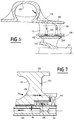
- FIG. 7 shows an exemplary embodiment of the bearing 126 for supporting the main shaft 101 on the side of the gas turbine 103. It can be seen that this bearing 126, produced as an example by a doublet of ball bearings, is lubricated and cooled by a recirculated flow taken at the outlet of the rectifier 111 in a medium-pressure zone through the wall of the rear bottom 153 delimiting the return channel 112, by a recirculation channel 139 constituting a collection close to the bearing 126.
- the flow taken and used for the lubrication of the bearing 126 is rejected at a point of the low pressure machine, such as for example the inlet of the BP pump by a circuit comprising a passage 141, a channel 142 included in the main shaft 101 and coaxial with it ( Figure 7) and an outlet passage 154 through the secondary rotor 104 ( Figure 1).
- a circuit comprising a passage 141, a channel 142 included in the main shaft 101 and coaxial with it ( Figure 7) and an outlet passage 154 through the secondary rotor 104 ( Figure 1).
- the doublet with ball bearings 126 shown in Figure 7 can be replaced by a bearing suitable for high speeds which is of another type.
- the bearing 126 can thus be a fluid or foil bearing supplied with medium-pressure fluid by a recirculation channel completely analogous to the channel 139 in FIG. 7.
- the bearing 126 can also be constituted by an active magnetic bearing cooled by a low flow of medium pressure fluid withdrawn by the recirculation channel 139.
- the seal 140 makes it possible in all cases to ensure a seal with respect to the zone in which the gas turbine 103 is located.
- the gas turbine 103 may include one or more stages 121, 122 mounted directly at the end of the main shaft 101 and supplying all of the power necessary for the HP and LP pumps.
- the turbine wheels 121, 122 can be mounted by a long tie rod 123 coaxial with the main shaft 101 and an elastic support piece limiting the differential expansions between the pieces.
- the turbine 103 comprises a casing 120 in which are integrated a channel 118 for supplying hot gases and an annular space 119 for applying hot gases to the blades of the turbine wheels 121, 122.
- a end of the casing 120 of the turbine 103 can be connected to the casing 102 of the HP and LP pumps by a connection comprising radial pins 116.
- FIGS. 8 and 9 show examples of dynamic seals produced between the secondary shaft 104 constituting the rotor of the LP pump and the members 130, 114 integral with the main shaft 101 constituting the rotor of the HP pump.
- Fluid seals 147, 148 such as labyrinths with wipers, rings or floating rings are thus disposed between the portion 129 of the rectifier 111 or the rotor 104 and the support 130 of the HP impeller 114.
- a fluid seal 146 is also disposed between the secondary rotor 104 and the upstream end of the BP rectifier 111 located near the BP 110 impeller, with an opening opposite that of the fluid seals 147, 148.
- Dynamic sealing means 144, 145 are moreover arranged between the impeller BP 110 mounted on the secondary rotor 104 and the bypass channel 162 (FIGS. 1, 8 and 9). These dynamic sealing means likewise comprise fluid seals such as labyrinths with wipers which have a clearance in operation minimizing the fluid flow rates between the flow of fluid HP derivative 163 and the flow of fluid BP input 107.
- the operating clearances of the various fluid seals also make it possible to adjust the leakage flow rate towards the inlet of the LP pump to the strict need of the low pressure / high pressure bearings and thus to participate in an optimal management of the leaks.
- the flow rate thus sampled for the lubrication of these bearings in the preferred embodiment is obtained without mounting or additional part.
Landscapes
- Engineering & Computer Science (AREA)
- Mechanical Engineering (AREA)
- General Engineering & Computer Science (AREA)
- Chemical & Material Sciences (AREA)
- Combustion & Propulsion (AREA)
- Structures Of Non-Positive Displacement Pumps (AREA)
Applications Claiming Priority (2)
| Application Number | Priority Date | Filing Date | Title |
|---|---|---|---|
| FR9016547 | 1990-12-31 | ||
| FR9016547A FR2671142B1 (fr) | 1990-12-31 | 1990-12-31 | Turbopompe a gavage integre en flux derive. |
Publications (2)
| Publication Number | Publication Date |
|---|---|
| EP0494006A1 true EP0494006A1 (de) | 1992-07-08 |
| EP0494006B1 EP0494006B1 (de) | 1995-08-23 |
Family
ID=9403883
Family Applications (1)
| Application Number | Title | Priority Date | Filing Date |
|---|---|---|---|
| EP91403485A Expired - Lifetime EP0494006B1 (de) | 1990-12-31 | 1991-12-20 | Turbopumpe mit einer durch Bypassströmung angetriebenen Überdruckpumpe |
Country Status (5)
| Country | Link |
|---|---|
| US (1) | US5224817A (de) |
| EP (1) | EP0494006B1 (de) |
| JP (1) | JPH04314952A (de) |
| DE (1) | DE69112368T2 (de) |
| FR (1) | FR2671142B1 (de) |
Cited By (1)
| Publication number | Priority date | Publication date | Assignee | Title |
|---|---|---|---|---|
| RU2169862C2 (ru) * | 1999-06-21 | 2001-06-27 | Открытое акционерное общество Самарский научно-технический комплекс им. Н.Д. Кузнецова | Турбонасосный агрегат |
Families Citing this family (11)
| Publication number | Priority date | Publication date | Assignee | Title |
|---|---|---|---|---|
| US7828511B1 (en) | 2008-03-18 | 2010-11-09 | Florida Turbine Technologies, Inc. | Axial tip turbine driven pump |
| US7931441B1 (en) | 2008-03-18 | 2011-04-26 | Florida Turbine Technologies, Inc. | Inducer with tip shroud and turbine blades |
| RU2391563C1 (ru) * | 2009-02-24 | 2010-06-10 | Николай Борисович Болотин | Центробежный насос |
| US20110116934A1 (en) * | 2009-11-16 | 2011-05-19 | Meng Sen Y | Pumping element design |
| RU2445514C1 (ru) * | 2010-12-23 | 2012-03-20 | Николай Борисович Болотин | Шнекоцентробежный насос |
| US9206820B2 (en) | 2012-06-11 | 2015-12-08 | Aerojet Rocketdyne, Inc. | Inducer with cavitation instability controls to reduce vibrations and radial loads |
| US9816512B2 (en) * | 2015-07-15 | 2017-11-14 | Borgwarner Inc. | Separated opposed flow single coupling compressor stage |
| RU172261U1 (ru) * | 2016-03-21 | 2017-07-03 | Игорь Борисович Широков | Бесколлекторный бессальниковый безосевой двигатель-винт/вентилятор |
| KR102133130B1 (ko) * | 2019-08-12 | 2020-07-10 | 신영환 | 듀얼 블레이드 송풍장치 |
| CN112431788B (zh) * | 2020-10-29 | 2022-04-22 | 北京航天动力研究所 | 一种高速低泄漏液封轮浮动环组合式密封装置 |
| CN121452147B (zh) * | 2026-01-06 | 2026-04-07 | 福龙马集团股份有限公司 | 一种集成式双模水泵 |
Citations (6)
| Publication number | Priority date | Publication date | Assignee | Title |
|---|---|---|---|---|
| DE885050C (de) * | 1950-11-29 | 1953-08-03 | Bruno C Grosskopf | Axial-Kreiselmaschine, insbesondere Pumpe, Kompressor u. dgl. |
| US3004494A (en) * | 1957-11-14 | 1961-10-17 | Thompson Ramo Wooldridge Inc | Turbine driven pump inducer |
| US3093084A (en) * | 1961-02-21 | 1963-06-11 | Derderian George | Pump |
| US3103176A (en) * | 1958-12-16 | 1963-09-10 | G & J Weir Ltd | Turbine-driven centrifugal pump |
| US4449888A (en) * | 1982-04-23 | 1984-05-22 | Balje Otto E | Free spool inducer pump |
| EP0374020A1 (de) * | 1988-12-12 | 1990-06-20 | Societe Europeenne De Propulsion | Kompakte Hochdruckturbopumpe zur Versorgung eines Raketenmotors mit Treibstoff |
Family Cites Families (11)
| Publication number | Priority date | Publication date | Assignee | Title |
|---|---|---|---|---|
| US358777A (en) * | 1887-03-01 | Htdeaulic motor | ||
| DE1001113B (de) * | 1954-04-17 | 1957-01-17 | Ernst Beck Dr Ing | Einrichtung zur Verminderung der bei Kreiselpumpen erforderlichen Zulaufhoehe |
| US2771036A (en) * | 1955-01-19 | 1956-11-20 | Baez Guillermo Federico | Rotary pumps and the like |
| US2832292A (en) * | 1955-03-23 | 1958-04-29 | Edwards Miles Lowell | Pump assemblies |
| FR1343011A (fr) * | 1962-10-09 | 1963-11-15 | Machine tournante à flux croisés en série | |
| US4400134A (en) * | 1980-02-22 | 1983-08-23 | Eurotech International Limited | Collector apparatus |
| US4375938A (en) * | 1981-03-16 | 1983-03-08 | Ingersoll-Rand Company | Roto-dynamic pump with a diffusion back flow recirculator |
| DE3111212A1 (de) * | 1981-03-21 | 1982-09-30 | Klöckner-Humboldt-Deutz AG, 5000 Köln | Fluessigkeitspumpe |
| US4408953A (en) * | 1982-01-06 | 1983-10-11 | Chandler Evans Inc | High efficiency centrifugal pump |
| US4834611A (en) * | 1984-06-25 | 1989-05-30 | Rockwell International Corporation | Vortex proof shrouded inducer |
| US4981018A (en) * | 1989-05-18 | 1991-01-01 | Sundstrand Corporation | Compressor shroud air bleed passages |
-
1990
- 1990-12-31 FR FR9016547A patent/FR2671142B1/fr not_active Expired - Fee Related
-
1991
- 1991-12-18 US US07/809,968 patent/US5224817A/en not_active Expired - Lifetime
- 1991-12-20 DE DE69112368T patent/DE69112368T2/de not_active Expired - Fee Related
- 1991-12-20 EP EP91403485A patent/EP0494006B1/de not_active Expired - Lifetime
- 1991-12-27 JP JP3346645A patent/JPH04314952A/ja active Pending
Patent Citations (6)
| Publication number | Priority date | Publication date | Assignee | Title |
|---|---|---|---|---|
| DE885050C (de) * | 1950-11-29 | 1953-08-03 | Bruno C Grosskopf | Axial-Kreiselmaschine, insbesondere Pumpe, Kompressor u. dgl. |
| US3004494A (en) * | 1957-11-14 | 1961-10-17 | Thompson Ramo Wooldridge Inc | Turbine driven pump inducer |
| US3103176A (en) * | 1958-12-16 | 1963-09-10 | G & J Weir Ltd | Turbine-driven centrifugal pump |
| US3093084A (en) * | 1961-02-21 | 1963-06-11 | Derderian George | Pump |
| US4449888A (en) * | 1982-04-23 | 1984-05-22 | Balje Otto E | Free spool inducer pump |
| EP0374020A1 (de) * | 1988-12-12 | 1990-06-20 | Societe Europeenne De Propulsion | Kompakte Hochdruckturbopumpe zur Versorgung eines Raketenmotors mit Treibstoff |
Non-Patent Citations (1)
| Title |
|---|
| RUSSIAN ENGINEERING JOURNAL, vol. 53, no. 11, 1973, pages 31-35; O.V. BAIBAKOV et al.: "Better power/speed cavitation for centrifugal pumps" * |
Cited By (1)
| Publication number | Priority date | Publication date | Assignee | Title |
|---|---|---|---|---|
| RU2169862C2 (ru) * | 1999-06-21 | 2001-06-27 | Открытое акционерное общество Самарский научно-технический комплекс им. Н.Д. Кузнецова | Турбонасосный агрегат |
Also Published As
| Publication number | Publication date |
|---|---|
| EP0494006B1 (de) | 1995-08-23 |
| US5224817A (en) | 1993-07-06 |
| FR2671142B1 (fr) | 1993-04-23 |
| FR2671142A1 (fr) | 1992-07-03 |
| DE69112368D1 (de) | 1995-09-28 |
| JPH04314952A (ja) | 1992-11-06 |
| DE69112368T2 (de) | 1996-02-08 |
Similar Documents
| Publication | Publication Date | Title |
|---|---|---|
| EP0494007B1 (de) | Einzeldurchfluss-Turbopumpe mit integrierter Überdruckpumpe | |
| EP0494008B1 (de) | Turbopumpe mit einer durch axialer Durchströmung angetriebenen Überdruckpumpe | |
| CA2758175C (fr) | Moteur a turbine a gaz a double corps pourvu d ' un palier inter-arbres | |
| EP0494006B1 (de) | Turbopumpe mit einer durch Bypassströmung angetriebenen Überdruckpumpe | |
| FR2598179A1 (fr) | Dispositif de transfert d'air de refroidissement pour une turbine | |
| FR3049008A1 (fr) | Turboreacteur comprenant un arbre basse pression supercritique | |
| EP2612037A1 (de) | Turbopumpe, im besonderen zur versorgung von raketenmotoren mit gas | |
| FR2698661A1 (fr) | Turbopompe compacte de forte puissance pour moteur-fusée. | |
| FR3008749A1 (fr) | Pompe centrifuge, en particulier pour l'alimentation de moteurs de fusee | |
| EP3726097A1 (de) | Mechanisches reduktionsgetriebe für luftfahrzeug-turbotriebwerk | |
| FR3046200B1 (fr) | Turbomachine comprenant un reservoir d'huile et un echangeur air-huile associe | |
| WO2019038510A1 (fr) | Turboreacteur a double corps ayant un palier de butee d'arbre basse pression positionne dans le carter d'echappement | |
| FR2464363A1 (fr) | Rotor de turbine pour turbomachines avec systeme de transfert de l'agent de refroidissement | |
| BE1025642A1 (fr) | Carter de compresseur avec reservoir d'huile pour turbomachine | |
| EP3861195B1 (de) | Turbofantriebwerk mit einem durch seine sekundärströmung gekühlten auslasskegel | |
| WO2021116620A1 (fr) | Système propulsif aéronautique à faible débit de fuite et rendement propulsif amélioré | |
| FR2961856A1 (fr) | Trompe a jet pour enceinte de palier d'une turbomachine alimentee par l'huile de lubrification | |
| EP1473462B1 (de) | Patrone zum Zusammenbau eines Verdichters | |
| FR3104206A1 (fr) | Enceinte de lubrification pour une turbomachine d’aeronef | |
| FR3134428A1 (fr) | Système de lubrification commun à deux enceintes d’une turbomachine | |
| WO2025068641A1 (fr) | Dispositif pour le centrage et le guidage en rotation d'un arbre de turbomachine à lubrification optimisée d'éléments de roulement par du lubrifiant évacué depuis un sfd | |
| EP4479640A1 (de) | Kraftstoffregelsystem | |
| WO2024227580A1 (fr) | Ensemble de pompage de fluide dans un compartiment interne de turbomachine | |
| FR3137409A1 (fr) | Compresseur pour aéronef | |
| WO2026082319A1 (fr) | Compresseur haute vitesse compartimente comprenant un systeme de refroidissement de la pivoterie dudit compresseur |
Legal Events
| Date | Code | Title | Description |
|---|---|---|---|
| PUAI | Public reference made under article 153(3) epc to a published international application that has entered the european phase |
Free format text: ORIGINAL CODE: 0009012 |
|
| AK | Designated contracting states |
Kind code of ref document: A1 Designated state(s): DE IT |
|
| 17P | Request for examination filed |
Effective date: 19921212 |
|
| 17Q | First examination report despatched |
Effective date: 19931227 |
|
| GRAA | (expected) grant |
Free format text: ORIGINAL CODE: 0009210 |
|
| AK | Designated contracting states |
Kind code of ref document: B1 Designated state(s): DE IT |
|
| REF | Corresponds to: |
Ref document number: 69112368 Country of ref document: DE Date of ref document: 19950928 |
|
| ITF | It: translation for a ep patent filed | ||
| PGFP | Annual fee paid to national office [announced via postgrant information from national office to epo] |
Ref country code: DE Payment date: 19951219 Year of fee payment: 5 |
|
| PLBE | No opposition filed within time limit |
Free format text: ORIGINAL CODE: 0009261 |
|
| STAA | Information on the status of an ep patent application or granted ep patent |
Free format text: STATUS: NO OPPOSITION FILED WITHIN TIME LIMIT |
|
| 26N | No opposition filed | ||
| PG25 | Lapsed in a contracting state [announced via postgrant information from national office to epo] |
Ref country code: DE Effective date: 19970902 |
|
| PGFP | Annual fee paid to national office [announced via postgrant information from national office to epo] |
Ref country code: IT Payment date: 20071212 Year of fee payment: 17 |
|
| PG25 | Lapsed in a contracting state [announced via postgrant information from national office to epo] |
Ref country code: IT Free format text: LAPSE BECAUSE OF NON-PAYMENT OF DUE FEES Effective date: 20081220 |