EP0494517A2 - Méthode et dispositif de commande de partinage de roues - Google Patents
Méthode et dispositif de commande de partinage de roues Download PDFInfo
- Publication number
- EP0494517A2 EP0494517A2 EP91311548A EP91311548A EP0494517A2 EP 0494517 A2 EP0494517 A2 EP 0494517A2 EP 91311548 A EP91311548 A EP 91311548A EP 91311548 A EP91311548 A EP 91311548A EP 0494517 A2 EP0494517 A2 EP 0494517A2
- Authority
- EP
- European Patent Office
- Prior art keywords
- demand
- engine
- reduced
- wheel spin
- actual
- Prior art date
- Legal status (The legal status is an assumption and is not a legal conclusion. Google has not performed a legal analysis and makes no representation as to the accuracy of the status listed.)
- Withdrawn
Links
Images

Classifications
-
- B—PERFORMING OPERATIONS; TRANSPORTING
- B60—VEHICLES IN GENERAL
- B60K—ARRANGEMENT OR MOUNTING OF PROPULSION UNITS OR OF TRANSMISSIONS IN VEHICLES; ARRANGEMENT OR MOUNTING OF PLURAL DIVERSE PRIME-MOVERS IN VEHICLES; AUXILIARY DRIVES FOR VEHICLES; INSTRUMENTATION OR DASHBOARDS FOR VEHICLES; ARRANGEMENTS IN CONNECTION WITH COOLING, AIR INTAKE, GAS EXHAUST OR FUEL SUPPLY OF PROPULSION UNITS IN VEHICLES
- B60K28/00—Safety devices for propulsion-unit control, specially adapted for, or arranged in, vehicles, e.g. preventing fuel supply or ignition in the event of potentially dangerous conditions
- B60K28/10—Safety devices for propulsion-unit control, specially adapted for, or arranged in, vehicles, e.g. preventing fuel supply or ignition in the event of potentially dangerous conditions responsive to conditions relating to the vehicle
- B60K28/16—Safety devices for propulsion-unit control, specially adapted for, or arranged in, vehicles, e.g. preventing fuel supply or ignition in the event of potentially dangerous conditions responsive to conditions relating to the vehicle responsive to, or preventing, spinning or skidding of wheels
Definitions
- the present invention relates to a method of and an apparatus for controlling wheel spin.
- Wheeled vehicles depend upon the maintenance of an adequate frictional contact between the driven wheels of the vehicle and the ground.
- the driving force at the driven wheels exceeds a value which is related to the weight acting on the driven wheels and the co-efficient of friction of the ground surface, the driven wheels slip with respect to the ground, thus exhibiting the phenomenon known as wheel spin.
- wheel spin is not a problem.
- surfaces of relatively poor co-efficient of friction such as water logged tarmac, ice, and muddy surfaces, poor driving technique can give rise to wheel spin.
- traction control system when excessive wheel spin is detected, the system reduces the quantity of mixture supplied to the engine, for instance by at least partially closing a throttle of an induction system of the engine.
- a disadvantage of this system is that it has a relatively poor response time because of the time taken to close the throttle and the delay between closing the throttle and reduction of engine output.
- Another known type of traction control system responds to excessive wheel spin by cutting off fuel for a predetermined pattern of engine fire events.
- Engine output is reduced with a much faster response time than for the previously mentioned system, but this technique of "fuel intervention" tends to increase the emissions of exhaust pollutants.
- an apparatus for controlling wheel spin for a vehicle driven by an internal combustion engine comprising means for detecting when wheel spin exceeds a predetermined threshold, means responsive to the detection means for producing a reduced engine demand, means for forming a threshold value which is inversely dependent on the difference between the reduced engine demand and actual engine demand, and means for cutting off the supply of fuel for a predetermined pattern of engine fire events when the wheel spin exceeds the threshold value.
- a method of controlling wheel spin for a vehicle driven by an internal combustion engine comprising detecting when wheel spin exceeds a predetermined threshold, producing a reduced engine demand, forming a threshold value which is inversely dependent on the difference between the reduced engine demand and actual engine demand, and cutting off the supply of fuel for a predetermined pattern of engine fire events when the wheel spin exceeds the threshold value.
- the reduced and actual engine demands may be reduced and actual engine throttle demands.
- the reduced and actual engine demands may be reduced and actual engine air mass flow demand.
- the reduced engine throttle demand and the actual engine throttle demand may comprise a reduced throttle angle demand and an actual throttle angle.
- the threshold value is a linear function of the difference.
- the threshold value may be proportional to the difference between a constant and the difference between the reduced and actual engine throttle demands.
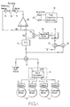
- a vehicle is driven by an internal combustion engine (not shown) controlled by an engine management system including a traction control system as shown in Figure 1.
- the vehicle has a pair of driven wheels 3 connected by a transmission (not shown) to the engine.
- the vehicle also has a pair of undriven wheels 4.
- the wheels 3 and 4 are provided with respective sensors 5, such as variable reluctance transducers co-operating with toothed wheels, which provide signals representing the speeds of the wheels.
- the wheel speed signals are supplied to an anti-lock brake system 6 which includes a spin calculator 7 for providing an output signal representing the amount of wheel spin detected.
- the spin calculator 7 compares the speeds of the driven wheels 3 with the speeds of the undriven wheels 4 in order to detect excessive driven wheel speed and supplies a spin signal corresponding to the difference between driven wheel speed and undriven wheel speed.
- the spin calculator 7 and the sensors 5 may be provided in order to permit traction or wheel spin control.
- wheel spin may be determined in other ways, for instance, by comparing the speed of each wheel with an average speed of all wheels or by comparing wheel speed with vehicle speed determined by a speed over ground sensor or the like.
- Wheel spin control may also be provided for all-wheel drive vehicles, for instance using one of the above mentioned alternative wheel spin detection techniques in place of the comparison with undriven wheel speed illustrated in the drawings.
- the output of the spin calculator 7 is supplied to the summing input of a subtracter 8 whose subtracting input receives a target spin value.
- the output of the subtracter 8 is supplied to a proportional/integral/differential (PID) controller 9 which has a transfer function having a linear combination of proportional, integral and differential terms.
- PID proportional/integral/differential
- the output of the controller 9 supplies a signal ⁇ d representing a reduced throttle angle demand value, which is supplied to the non-inverting input of an amplifier 10 forming part of a servo feedback throttle angle controller.
- the output of the amplifier 10 is supplied to a motor 11, whose output shaft is coupled to a throttle 12 within an induction system of the engine.
- the angular position of the throttle 12 is sensed by a position sensor 13, such as a potentiometer, which supplies an output signal ⁇ a representing the actual throttle angle to the inverting input of the amplifier 10.
- the demanded and actual throttle angle values are supplied to the summing and subtracting inputs of a subtracter 14, whose output is supplied to an absolute value circuit 15.
- the output of the circuit 15 is supplied to a multiplier 16, which multiplies the absolute value of the difference between the demanded and actual throttle angles by a constant 2/k.
- the output of the multiplier 16 is supplied to the subtracting input of a subtracter 17, whose summing input receives a signal representing 2.
- the output of the subtracter 17 forms a fuel intervention threshold value which is supplied to the subtracting input of a subtracter 18, whose summing input is connected to the output of the subtracter 8.
- the output of the subtracter 18 is connected to the input of a fuel injection controller 19, which has a plurality of outputs for controlling the operation of fuel injectors 20.
- the traction control system During normal operation in the absence of excessive wheel spin i.e. when the wheel spin calculated by the calculator 7 is less than the target spin value, the traction control system is disabled and engine operation is controlled by the engine management system in the normal way. However, when wheel spin exceeds the target spin value, the traction control system shown in Figure 1 takes control of the engine management system in order to reduce or eliminate wheel spin. Throttle intervention effectively operates with zero threshold and responds to the detection of any excessive wheel spin.
- the controller 9 responds to the wheel spin by providing a reduced throttle angle demand ⁇ d which causes the servo feedback control arrangement to reduce the opening angle of the throttle 12 by an amount which is dependent on the degree of wheel spin.
- the throttle 12 cannot respond instantly to the reduced throttle angle demand and, as is known, the difference between actual and demanded throttle angles drives the servo, which closes the throttle to the reduced demanded angle as quickly as possible within constraints, such as loop stability and minimal overshoot.
- the absolute value of the difference between the demanded and actual throttle angles is multiplied by the constant factor 2/k and subtracted from the constant value 2 in order to form a variable threshold signal for fuelling intervention.
- the throttle intervention acts with a zero wheel spin threshold
- the constant k is chosen so that the expression ( ⁇ d- ⁇ a) has a value between 0 and 1.
- the value of the constant k may be equal to the value of the total angular range of movement of the throttle 12.
- fuelling intervention operates when wheel spin exceeds a threshold of approximately two kilometers per hour. This is typical in the case of relatively small reductions in throttle angle, for instance when relatively small levels of excessive wheel spin are detected. Thus, fuelling intervention does not operate or operates for only relatively small periods.
- the fuel injection controller 19 controls the fuel injectors 20 so as to cut off fuelling for a predetermined pattern of cylinder events or fire periods.
- a predetermined pattern of cylinder events or fire periods For instance, the technique described in European Patent Specification No. 0 443 785 may be used for this purpose in order to reduce engine output rapidly and in a predictable manner.
- the traction control system is thus capable of responding rapidly by, if necessary, using fuelling intervention for transient periods until throttle intervention control can take over.
- Figures 2 and 3 of the accompanying drawings show a relatively small reduced throttle angle demand from a throttle position shown at 21 for normal vehicle operation to a level shown at 24 for traction control in order to reduce or eliminate wheel spin. 22 indicates the part of the curve between the times T1 and T2.
- the demanded throttle angle is reduced by the controller 9 relatively rapidly to the value represented by 24.
- the actual throttle angle as represented by the broken line 23 cannot respond sufficiently quickly to follow the demanded angle so that, between the times T1 and T2, there is a substantial difference between the actual and demanded throttle angles.
- the fuelling intervention threshold varies in accordance with the equation given above and, if the amount of wheel spin exceeds this threshold, engine output is reduced by fuelling intervention for a relatively short period of time. For smaller amounts of excessive wheel spin, no fuelling intervention is required.
- FIG 3 is a similar graph to Figure 2 but illustrates operation for a much larger reduced throttle angle demand.
- a difference exists between the actual and demanded throttle angles for a much longer time interval from T3 to T4.
- the greater reduction in throttle angle demand results in a much lower fuelling intervention threshold T, at least during an initial part of the time interval T3 to T4.
- fuelling intervention is more likely to take place in order for the traction control system to provide a rapid response.
- the threshold T rises fuelling intervention is less likely and eventually ceases so that subsequent traction control is performed by throttle intervention.
- the principal control strategy is throttle intervention with fuelling intervention acting transiently in order to decrease the traction control system response time whenever necessary. Because the fuelling intervention acts only transiently, exhaust emissions are not substantially increased.
Landscapes
- Engineering & Computer Science (AREA)
- Chemical & Material Sciences (AREA)
- Combustion & Propulsion (AREA)
- Transportation (AREA)
- Mechanical Engineering (AREA)
- Control Of Vehicle Engines Or Engines For Specific Uses (AREA)
- Electrical Control Of Air Or Fuel Supplied To Internal-Combustion Engine (AREA)
- Control Of Throttle Valves Provided In The Intake System Or In The Exhaust System (AREA)
- Combined Controls Of Internal Combustion Engines (AREA)
Applications Claiming Priority (2)
| Application Number | Priority Date | Filing Date | Title |
|---|---|---|---|
| GB9100224 | 1991-01-05 | ||
| GB919100224A GB9100224D0 (en) | 1991-01-05 | 1991-01-05 | Method of and apparatus for controlling wheel spin |
Publications (2)
| Publication Number | Publication Date |
|---|---|
| EP0494517A2 true EP0494517A2 (fr) | 1992-07-15 |
| EP0494517A3 EP0494517A3 (en) | 1993-02-03 |
Family
ID=10688024
Family Applications (1)
| Application Number | Title | Priority Date | Filing Date |
|---|---|---|---|
| EP19910311548 Withdrawn EP0494517A3 (en) | 1991-01-05 | 1991-12-11 | Method of and apparatus for controlling wheel spin |
Country Status (4)
| Country | Link |
|---|---|
| US (1) | US5369586A (fr) |
| EP (1) | EP0494517A3 (fr) |
| JP (1) | JPH04295147A (fr) |
| GB (1) | GB9100224D0 (fr) |
Cited By (2)
| Publication number | Priority date | Publication date | Assignee | Title |
|---|---|---|---|---|
| GB2279111A (en) * | 1993-06-18 | 1994-12-21 | Delco Electronics Corp | Vehicle wheel slip traction control |
| US8585156B2 (en) | 2005-11-02 | 2013-11-19 | Hitachi Construction Machinery Co., Ltd. | Travel control device for work vehicle and work vehicle |
Families Citing this family (8)
| Publication number | Priority date | Publication date | Assignee | Title |
|---|---|---|---|---|
| JP3206224B2 (ja) * | 1993-06-30 | 2001-09-10 | 日産自動車株式会社 | 車両用トラクション制御装置 |
| US5769054A (en) * | 1993-10-13 | 1998-06-23 | Robert Bosch Gmbh | Method and arrangement for controlling the torque of internal combustion engine while deactivating individual cylinders |
| DE4435741C5 (de) * | 1994-10-06 | 2007-05-31 | Robert Bosch Gmbh | Verfahren und Vorrichtung zur Steuerung einer Brennkraftmaschine |
| DE19527840B4 (de) * | 1995-07-28 | 2004-09-16 | Siemens Ag | Schaltungsanordnung zum Steuern des zwischen den Antriebsrädern eines Kraftfahrzeugs und der Fahrbahn übertragenen Drehmoments |
| US5749428A (en) * | 1996-03-05 | 1998-05-12 | Ford Global Technologies, Inc. | Traction control through an effective static linearization |
| JP3585651B2 (ja) * | 1996-06-19 | 2004-11-04 | 株式会社ホンダエレシス | 車両のアンチロックブレーキ制御装置 |
| JP3358452B2 (ja) * | 1996-07-22 | 2002-12-16 | 日産自動車株式会社 | 車両のエンジンブレーキ制御装置 |
| JP4339321B2 (ja) * | 2006-01-20 | 2009-10-07 | 本田技研工業株式会社 | 内燃機関の制御装置 |
Family Cites Families (22)
| Publication number | Priority date | Publication date | Assignee | Title |
|---|---|---|---|---|
| CA1312129C (fr) * | 1986-03-04 | 1992-12-29 | Honda Giken Kogyo Kabushiki Kaisha (Also Trading As Honda Motor Co., Ltd .) | Systeme anti-derapage pour vehicules routiers |
| CA1311543C (fr) * | 1986-05-09 | 1992-12-15 | Shuji Shiraishi | Systeme anti-derapage pour vehicules routiers |
| CA1306784C (fr) * | 1986-06-09 | 1992-08-25 | Masakazu Sakaguchi | Methode permettant de reduire le patinage des roues motrices d'un vehicule |
| US4721176A (en) * | 1986-06-13 | 1988-01-26 | General Motors Corporation | Vehicle traction control system |
| JPS63186942A (ja) * | 1987-01-27 | 1988-08-02 | Mazda Motor Corp | 自動車用エンジンの燃料停止装置 |
| SE466143B (sv) * | 1987-04-17 | 1992-01-07 | Honda Motor Co Ltd | Traktionsregleranordning foer fordon |
| EP0287862B1 (fr) * | 1987-04-20 | 1993-06-02 | Mitsubishi Jidosha Kogyo Kabushiki Kaisha | Appareil de commande de la friction d'entraînement pour un moteur de véhicule |
| DE3883875T2 (de) * | 1987-06-11 | 1994-01-05 | Honda Motor Co Ltd | Antriebsrad-Schlupfsteuersystem für Fahrzeuge. |
| DE3888871T2 (de) * | 1987-06-11 | 1994-07-21 | Honda Motor Co Ltd | Antischlupfregelung für die angetriebenen Räder von Fahrzeugen. |
| JPS6487844A (en) * | 1987-09-29 | 1989-03-31 | Toyota Motor Corp | Engine brake control device |
| JPH01155038A (ja) * | 1987-12-10 | 1989-06-16 | Honda Motor Co Ltd | 駆動輪スリップ制御装置 |
| US5046009A (en) * | 1987-11-05 | 1991-09-03 | Nissan Motor Company, Limited | Slip suppressive drive control system for automotive vehicle with reduction of power output of internal combustion engine |
| JP2605089B2 (ja) * | 1988-03-23 | 1997-04-30 | 本田技研工業株式会社 | 駆動輪の過剰スリップ制御装置 |
| US5019989A (en) * | 1988-12-01 | 1991-05-28 | Mitsubishi Jidosha Kogyo Kabushiki Kaisha | Vehicle engine output control method and apparatus |
| JP2643420B2 (ja) * | 1989-03-06 | 1997-08-20 | トヨタ自動車株式会社 | 車両の加速スリップ制御装置 |
| JPH02271038A (ja) * | 1989-04-12 | 1990-11-06 | Toyota Motor Corp | 車両の加速スリップ制御装置 |
| JPH0323632U (fr) * | 1989-07-17 | 1991-03-12 | ||
| US5172319A (en) * | 1989-11-13 | 1992-12-15 | Honda Giken Kogyo Kabushiki Kaisha | Drive wheel slip control system for vehicle |
| JP2876662B2 (ja) * | 1989-12-05 | 1999-03-31 | アイシン精機株式会社 | スロットル制御装置 |
| US5163530A (en) * | 1989-12-11 | 1992-11-17 | Nissan Motor Company, Limited | Control system for controlling driving torque delivered for driven wheels |
| DE4101385C2 (de) * | 1990-01-19 | 1996-07-04 | Honda Motor Co Ltd | Vorrichtung zum Steuern des Antriebsdrehmoments eines Antriebsrads |
| US5137105A (en) * | 1990-01-19 | 1992-08-11 | Honda Giken Kogyo Kabushiki Kaisha | System and method for controlling torque of driving wheel |
-
1991
- 1991-01-05 GB GB919100224A patent/GB9100224D0/en active Pending
- 1991-12-11 EP EP19910311548 patent/EP0494517A3/en not_active Withdrawn
- 1991-12-12 US US07/805,569 patent/US5369586A/en not_active Expired - Fee Related
- 1991-12-27 JP JP3347067A patent/JPH04295147A/ja not_active Withdrawn
Cited By (4)
| Publication number | Priority date | Publication date | Assignee | Title |
|---|---|---|---|---|
| GB2279111A (en) * | 1993-06-18 | 1994-12-21 | Delco Electronics Corp | Vehicle wheel slip traction control |
| GB2279111B (en) * | 1993-06-18 | 1996-04-17 | Delco Electronics Corp | Traction controller |
| US8585156B2 (en) | 2005-11-02 | 2013-11-19 | Hitachi Construction Machinery Co., Ltd. | Travel control device for work vehicle and work vehicle |
| EP1950468B1 (fr) * | 2005-11-02 | 2015-09-23 | Hitachi Construction Machinery Co., Ltd | Dispositif de commande de deplacement pour vehicule utilitaire et vehicule utilitaire |
Also Published As
| Publication number | Publication date |
|---|---|
| GB9100224D0 (en) | 1991-02-20 |
| EP0494517A3 (en) | 1993-02-03 |
| US5369586A (en) | 1994-11-29 |
| JPH04295147A (ja) | 1992-10-20 |
Similar Documents
| Publication | Publication Date | Title |
|---|---|---|
| US5303794A (en) | Wheel spin control using electronically controlled clutches and engine controls | |
| US6002979A (en) | Traction control system for automotive vehicles | |
| US5025882A (en) | Vehicle traction control system | |
| US5369586A (en) | Method of and apparatus for controlling wheel spin | |
| US5373447A (en) | Method of and apparatus for vehicle traction control by detecting wheel spin | |
| US5852330A (en) | Vehicle acceleration slip control system | |
| US5033002A (en) | Vehicle traction controller/road friction and hill slope tracking system | |
| EP0355975B1 (fr) | Méthode et système de boucle de commande à retours multiples pour commander le dérapage des roues | |
| EP0546175B1 (fr) | Systeme anti-patinage a l'acceleration pour vehicules a moteur | |
| US4911259A (en) | Running control method and running control system | |
| US5867803A (en) | Traction control apparatus | |
| EP0493911B1 (fr) | Méthode et dispositif pour commander le patinage des roues | |
| US5809443A (en) | Four-wheel drive transfer case controller with compensation for tires with different diameters | |
| GB2386206A (en) | A system for and a method of controlling idle speed of an internal combustion engine | |
| US5682316A (en) | Vehicle traction controller with engine and brake control | |
| US5107429A (en) | Adaptive throttle controller for vehicle traction control | |
| KR19980032863A (ko) | 차량의 구동력 제어장치 | |
| WO2013104617A1 (fr) | Procédé pour réduire la consommation de carburant d'un véhicule pendant le roulage en roue libre | |
| EP0641684B1 (fr) | Dispositif de commande de propulsion d'un véhicule | |
| US6282481B1 (en) | Driving force control apparatus for vehicles | |
| EP0486878A1 (fr) | Dispositif de commande de glissement d'accélération pour un véhicule | |
| US5313922A (en) | Method for controlling a flow of fuel to an engine of a vehicle during overrun operation | |
| US5899290A (en) | Engine output control apparatus | |
| US20030168274A1 (en) | Four wheel drive assembly and a method for utilizing the same | |
| EP0485779B1 (fr) | Dispositif de commande de glissement d'accélération pour véhicule |
Legal Events
| Date | Code | Title | Description |
|---|---|---|---|
| PUAI | Public reference made under article 153(3) epc to a published international application that has entered the european phase |
Free format text: ORIGINAL CODE: 0009012 |
|
| AK | Designated contracting states |
Kind code of ref document: A2 Designated state(s): DE ES FR GB IT SE |
|
| PUAL | Search report despatched |
Free format text: ORIGINAL CODE: 0009013 |
|
| AK | Designated contracting states |
Kind code of ref document: A3 Designated state(s): DE ES FR GB IT SE |
|
| 17P | Request for examination filed |
Effective date: 19930726 |
|
| 17Q | First examination report despatched |
Effective date: 19940615 |
|
| STAA | Information on the status of an ep patent application or granted ep patent |
Free format text: STATUS: THE APPLICATION IS DEEMED TO BE WITHDRAWN |
|
| 18D | Application deemed to be withdrawn |
Effective date: 19950621 |