EP0494581A2 - Machine à pistons rotatifs - Google Patents
Machine à pistons rotatifs Download PDFInfo
- Publication number
- EP0494581A2 EP0494581A2 EP91810934A EP91810934A EP0494581A2 EP 0494581 A2 EP0494581 A2 EP 0494581A2 EP 91810934 A EP91810934 A EP 91810934A EP 91810934 A EP91810934 A EP 91810934A EP 0494581 A2 EP0494581 A2 EP 0494581A2
- Authority
- EP
- European Patent Office
- Prior art keywords
- elevation
- housing
- rotary piston
- piston machine
- rib
- Prior art date
- Legal status (The legal status is an assumption and is not a legal conclusion. Google has not performed a legal analysis and makes no representation as to the accuracy of the status listed.)
- Granted
Links
- 238000007789 sealing Methods 0.000 claims abstract description 15
- 230000002093 peripheral effect Effects 0.000 claims abstract description 14
- 238000006073 displacement reaction Methods 0.000 claims description 2
- 230000015572 biosynthetic process Effects 0.000 abstract description 4
- 238000004519 manufacturing process Methods 0.000 abstract description 2
- 238000005096 rolling process Methods 0.000 description 3
- 238000013459 approach Methods 0.000 description 1
- 230000006835 compression Effects 0.000 description 1
- 238000007906 compression Methods 0.000 description 1
- 230000001419 dependent effect Effects 0.000 description 1
- 238000005265 energy consumption Methods 0.000 description 1
- 238000010587 phase diagram Methods 0.000 description 1
Images



Classifications
-
- F—MECHANICAL ENGINEERING; LIGHTING; HEATING; WEAPONS; BLASTING
- F01—MACHINES OR ENGINES IN GENERAL; ENGINE PLANTS IN GENERAL; STEAM ENGINES
- F01C—ROTARY-PISTON OR OSCILLATING-PISTON MACHINES OR ENGINES
- F01C21/00—Component parts, details or accessories not provided for in groups F01C1/00 - F01C20/00
- F01C21/10—Outer members for co-operation with rotary pistons; Casings
- F01C21/104—Stators; Members defining the outer boundaries of the working chamber
-
- F—MECHANICAL ENGINEERING; LIGHTING; HEATING; WEAPONS; BLASTING
- F01—MACHINES OR ENGINES IN GENERAL; ENGINE PLANTS IN GENERAL; STEAM ENGINES
- F01C—ROTARY-PISTON OR OSCILLATING-PISTON MACHINES OR ENGINES
- F01C19/00—Sealing arrangements in rotary-piston machines or engines
- F01C19/02—Radially-movable sealings for working fluids
Definitions
- the invention relates to a rotary piston machine with rotors enclosed in a common housing and rotatable about fixedly arranged axes, surfaces of the outer circumference of at least one of the rotors executing their orbital movement around one of the axes with a gap-forming distance along at least one cylindrical inner surface of the housing.
- the rotor takes on a larger diameter under the influence of centrifugal force and the operating temperature, and that the housing suffers from heat distortion.
- the sealing gap design aims at the fact that at the highest speed and most unfavorable temperature distribution there is a residual gap at all points which is just necessary to avoid the risk of large-area contact and consequent seizing of the rotor at the very high speeds that occur for example, 40 m / s and more, to be avoided with certainty
- the invention has for its object to improve the sealing of the peripheral surface of a rotor against the housing inner surface in a machine of the type mentioned so that the machine can be produced with relatively little effort, that the smallest possible sealing gap width is realized and that the risk of seizing the rotor is eliminated.
- the object is achieved in that at least one rib-like elevation formed from the housing material is provided on the inner surface of the housing, so that a sealing gap is formed between this elevation and the peripheral surface of the rotor, and that this sealing gap before the machine is started up for the first time is designed to be narrower than would be possible for non-contact operation in the entire speed and temperature range.
- the peripheral surface of the barrel approaches the tip of the rib-like elevation with increasing speed and rotor temperature and finally wears away from its material due to wear and tear.
- the rib-like elevation therefore only assumes its final shape and height when the machine runs in. In this way it is ensured that the rib-like elevation is never lower than is absolutely necessary for the runner to run freely.
- a rib-like elevation can be produced in a simple manner by cold forming, in that a groove is formed on the inside surface of the housing by stamping by means of a knife-shaped punch or by rolling in by means of a roller which is acute-angled in cross section, so that it is displaced as plastic on one or both sides of the groove arises.
- the inner-axis rotary piston machine shown in Figs. 1 and 2 e.g. for the compression of gaseous media, is known in its mode of operation from DE-B-34 32 915 (US-A-4,714, 417).
- Their inner rotor 1 and outer rotor 2 rotate about the axes 4, 5 which are fixed relative to the machine housing 3, so that the peripheral surfaces of both rotors 1, 2 move on circular paths, as the phase diagrams in FIG.
- the circumferential surfaces 8, 9, 10 of the outer rotor 2 which are shaped according to a circular cylinder surface, move at a constant, gap-forming, small distance along changing regions of the circular cylindrical inner surface 14 of the housing 3.
- the rib-like elevations 11, 16, which are essential to the invention, are provided in certain areas of the cylindrical inner surface 14 of the housing 3. They are not visible due to the representation scale in Fig. 1 and 2.
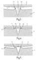
- FIG. 3 shows an enlarged detail from FIG. 2 in the region of the gap between the peripheral surface 9 of the outer rotor 2 and the inner surface 14 of the housing 3 with two of the rib-like elevations 11 according to the invention on both sides of a rolled-in groove 12 when the machine is new.
- the elevations 11 or the groove 12 run over the entire axial extent of the outer rotor 2 shown in FIG. 1.
- FIG. 4 shows the same enlarged detail as FIG. 3, but in the state of greatest approximation, due to centrifugal force and thermal expansion, of the peripheral surface 9 of the outer rotor 2 on the inner surface 14 of the housing 3 or on the rib-like elevations 11.
- the dashed lines 13 illustrate the very small volume of material removed by wear until the condition shown is reached.
- FIG. 5 again shows the same enlarged detail as FIG. 3, but in the state of average approximation of the peripheral surface 9 of the outer rotor 2 to the elevation 11.
- the sealing gap between the peripheral surface 9 and the elevations 11 is no further than it is for the freewheeling of the outer rotor 2 in the housing 3 taking into account all operating conditions is absolutely necessary.
- the width of the sealing gap is therefore the smallest possible.
- FIG. 6 shows a view of the cylindrical inner surface 14 of the housing 3, which is unwound in the plane, with the suction space 6 and the pressure space 7.
- the respective connections are indicated by arcs, the direction of flow by arrows.
- Figures 7, 8 and 9 illustrate how the sealing gap-forming elevations are created by material displacement by the one or two grooves squeezed out material forms a bulge-like bulge of the groove edges.
- FIG. 7 shows, for example, the formation of the groove 12 shown in FIG. 3 with the rib-like elevations 11 on both sides by rolling in by means of a roller 15.
- FIG. 8 shows the formation of a single rib-like elevation 16 on one side of a groove 17 by rolling in with an obliquely arranged correspondingly profiled roller 18.
Landscapes
- Engineering & Computer Science (AREA)
- Mechanical Engineering (AREA)
- General Engineering & Computer Science (AREA)
- Applications Or Details Of Rotary Compressors (AREA)
- Compressor (AREA)
Applications Claiming Priority (2)
| Application Number | Priority Date | Filing Date | Title |
|---|---|---|---|
| CH4139/90 | 1990-12-28 | ||
| CH4139/90A CH682587A5 (de) | 1990-12-28 | 1990-12-28 | Rotationskolbenmaschine. |
Publications (3)
| Publication Number | Publication Date |
|---|---|
| EP0494581A2 true EP0494581A2 (fr) | 1992-07-15 |
| EP0494581A3 EP0494581A3 (en) | 1992-08-26 |
| EP0494581B1 EP0494581B1 (fr) | 1995-03-22 |
Family
ID=4270546
Family Applications (1)
| Application Number | Title | Priority Date | Filing Date |
|---|---|---|---|
| EP91810934A Expired - Lifetime EP0494581B1 (fr) | 1990-12-28 | 1991-12-02 | Machine à pistons rotatifs |
Country Status (5)
| Country | Link |
|---|---|
| US (1) | US5147194A (fr) |
| EP (1) | EP0494581B1 (fr) |
| JP (1) | JPH05118281A (fr) |
| CH (1) | CH682587A5 (fr) |
| DE (1) | DE59105005D1 (fr) |
Families Citing this family (1)
| Publication number | Priority date | Publication date | Assignee | Title |
|---|---|---|---|---|
| CH685450A5 (de) * | 1992-04-01 | 1995-07-14 | Lindau Tech Forsch & Entw Gmbh | Innenachsige Drehkolbenmaschine. |
Family Cites Families (12)
| Publication number | Priority date | Publication date | Assignee | Title |
|---|---|---|---|---|
| DE547826C (de) * | 1928-07-27 | 1932-04-07 | Expl Des Procedes Maurice Lebl | Zahnradverdichter |
| DE556181C (de) * | 1930-03-18 | 1932-08-09 | Hugo Grasse | Zahnradmaschine mit Inneneingriff, insbesondere als Geblaese |
| US1993721A (en) * | 1934-01-11 | 1935-03-05 | Gulf Res & Dev Corp | Packing |
| US2902980A (en) * | 1956-04-26 | 1959-09-08 | Elmer G Barrett | Rotary motor and radial sliding vane therefor |
| FR1278136A (fr) * | 1960-10-27 | 1961-12-08 | Machine volumétrique à capacités engrenantes | |
| US3652191A (en) * | 1970-06-22 | 1972-03-28 | Trw Inc | Compressor |
| JPS5851286A (ja) * | 1981-09-22 | 1983-03-25 | Kayaba Ind Co Ltd | ギヤポンプの歯先シ−ル機構 |
| DE3219757A1 (de) * | 1982-05-26 | 1983-12-01 | Volkswagenwerk Ag, 3180 Wolfsburg | Dichtungsanordnung |
| CH664423A5 (de) * | 1984-06-12 | 1988-02-29 | Wankel Felix | Innenachsige drehkolbenmaschine. |
| US4717322A (en) * | 1986-08-01 | 1988-01-05 | Toyota Jidosha Kabushiki Kaisha | Roots-type fluid machine |
| DE3735433C2 (de) * | 1986-10-28 | 1996-02-29 | Volkswagen Ag | Verdrängermaschine für kompressible Medien |
| DE3721978A1 (de) * | 1987-07-03 | 1989-01-12 | Pierburg Gmbh | Drehkolbenmaschine |
-
1990
- 1990-12-28 CH CH4139/90A patent/CH682587A5/de not_active IP Right Cessation
-
1991
- 1991-11-20 US US07/796,050 patent/US5147194A/en not_active Expired - Fee Related
- 1991-12-02 EP EP91810934A patent/EP0494581B1/fr not_active Expired - Lifetime
- 1991-12-02 DE DE59105005T patent/DE59105005D1/de not_active Expired - Fee Related
- 1991-12-26 JP JP3345251A patent/JPH05118281A/ja active Pending
Also Published As
| Publication number | Publication date |
|---|---|
| JPH05118281A (ja) | 1993-05-14 |
| DE59105005D1 (de) | 1995-04-27 |
| EP0494581B1 (fr) | 1995-03-22 |
| US5147194A (en) | 1992-09-15 |
| CH682587A5 (de) | 1993-10-15 |
| EP0494581A3 (en) | 1992-08-26 |
Similar Documents
| Publication | Publication Date | Title |
|---|---|---|
| DE2617290C2 (fr) | ||
| DE2939945C2 (fr) | ||
| CH495509A (de) | Schneckenmaschine | |
| DE3815252A1 (de) | Ringmembranpumpe | |
| CH657897A5 (de) | Schraubenrotormaschine fuer ein arbeitsfluid. | |
| DE2732086A1 (de) | Innenachsige kreiskolbenmaschine mit kaemmeingriff und festpunktlos gelagertem innenzahnrad | |
| DE69709199T2 (de) | Innenzahnradmotor | |
| CH659296A5 (de) | Walze. | |
| DE1528983B2 (de) | Steuerdrehschiebereinrichtung fuer eine rotationskolbenmaschine | |
| DE3019642A1 (de) | Schnecken-arbeitsmaschine fuer fluide | |
| DE2365057A1 (de) | Druckmittelbetaetigte maschine, insbesondere parallel- und innenachsige rotationskolbenkraftmaschine oder -pumpe mit kaemmeingriff | |
| EP2561229A1 (fr) | Piston pour une machine à pistons radiaux | |
| DE19620482C2 (de) | Spiralkompressor mit einer Schrägfläche an einem Spiralteil | |
| WO2012010261A2 (fr) | Unité piston | |
| EP3507495B1 (fr) | Pompe à vide à vis | |
| DE102012206699A1 (de) | Zahnradmaschine mit wannenartiger Vertiefung an der Außenoberfläche des Gehäuses | |
| EP0494581B1 (fr) | Machine à pistons rotatifs | |
| CH663446A5 (de) | Aussenachsige rotationskolbenmaschine. | |
| EP0607497A1 (fr) | Pompe à engrenages internes avec joint d'étanchéité incorporé dans les dents | |
| DE102005058911B3 (de) | Hydraulische Maschine | |
| EP0077031B1 (fr) | Compresseur à pistons rotatifs | |
| DE3519170C2 (fr) | ||
| DE2552454A1 (de) | Drehkolbenmaschine, vorzugsweise fuer fluessigkeiten | |
| DE2421304A1 (de) | Parallel- und innenachsige rotationskolbenmaschine, insbesondere kraftmaschine oder pumpe, mit kaemmeingriff | |
| EP0784147B1 (fr) | Machine à piston rotatif |
Legal Events
| Date | Code | Title | Description |
|---|---|---|---|
| PUAI | Public reference made under article 153(3) epc to a published international application that has entered the european phase |
Free format text: ORIGINAL CODE: 0009012 |
|
| PUAL | Search report despatched |
Free format text: ORIGINAL CODE: 0009013 |
|
| AK | Designated contracting states |
Kind code of ref document: A2 Designated state(s): DE FR GB |
|
| AK | Designated contracting states |
Kind code of ref document: A3 Designated state(s): DE FR GB |
|
| 17P | Request for examination filed |
Effective date: 19921215 |
|
| 17Q | First examination report despatched |
Effective date: 19930723 |
|
| GRAA | (expected) grant |
Free format text: ORIGINAL CODE: 0009210 |
|
| AK | Designated contracting states |
Kind code of ref document: B1 Designated state(s): DE FR GB |
|
| REF | Corresponds to: |
Ref document number: 59105005 Country of ref document: DE Date of ref document: 19950427 |
|
| ET | Fr: translation filed | ||
| GBT | Gb: translation of ep patent filed (gb section 77(6)(a)/1977) |
Effective date: 19950619 |
|
| PGFP | Annual fee paid to national office [announced via postgrant information from national office to epo] |
Ref country code: GB Payment date: 19951116 Year of fee payment: 5 Ref country code: DE Payment date: 19951116 Year of fee payment: 5 |
|
| PGFP | Annual fee paid to national office [announced via postgrant information from national office to epo] |
Ref country code: FR Payment date: 19951120 Year of fee payment: 5 |
|
| PLBE | No opposition filed within time limit |
Free format text: ORIGINAL CODE: 0009261 |
|
| STAA | Information on the status of an ep patent application or granted ep patent |
Free format text: STATUS: NO OPPOSITION FILED WITHIN TIME LIMIT |
|
| 26N | No opposition filed | ||
| PG25 | Lapsed in a contracting state [announced via postgrant information from national office to epo] |
Ref country code: GB Effective date: 19961202 |
|
| GBPC | Gb: european patent ceased through non-payment of renewal fee |
Effective date: 19961202 |
|
| PG25 | Lapsed in a contracting state [announced via postgrant information from national office to epo] |
Ref country code: FR Effective date: 19970829 |
|
| PG25 | Lapsed in a contracting state [announced via postgrant information from national office to epo] |
Ref country code: DE Effective date: 19970902 |
|
| REG | Reference to a national code |
Ref country code: FR Ref legal event code: ST |