EP0495018B1 - Mecanisme de verrouillage pour galerie d'automobile - Google Patents
Mecanisme de verrouillage pour galerie d'automobile Download PDFInfo
- Publication number
- EP0495018B1 EP0495018B1 EP91909019A EP91909019A EP0495018B1 EP 0495018 B1 EP0495018 B1 EP 0495018B1 EP 91909019 A EP91909019 A EP 91909019A EP 91909019 A EP91909019 A EP 91909019A EP 0495018 B1 EP0495018 B1 EP 0495018B1
- Authority
- EP
- European Patent Office
- Prior art keywords
- article
- article carrier
- button
- securing member
- push button
- Prior art date
- Legal status (The legal status is an assumption and is not a legal conclusion. Google has not performed a legal analysis and makes no representation as to the accuracy of the status listed.)
- Expired - Lifetime
Links
Images


Classifications
-
- B—PERFORMING OPERATIONS; TRANSPORTING
- B60—VEHICLES IN GENERAL
- B60R—VEHICLES, VEHICLE FITTINGS, OR VEHICLE PARTS, NOT OTHERWISE PROVIDED FOR
- B60R9/00—Supplementary fittings on vehicle exterior for carrying loads, e.g. luggage, sports gear or the like
-
- B—PERFORMING OPERATIONS; TRANSPORTING
- B60—VEHICLES IN GENERAL
- B60R—VEHICLES, VEHICLE FITTINGS, OR VEHICLE PARTS, NOT OTHERWISE PROVIDED FOR
- B60R9/00—Supplementary fittings on vehicle exterior for carrying loads, e.g. luggage, sports gear or the like
- B60R9/04—Carriers associated with vehicle roof
- B60R9/048—Carriers characterised by article-gripping, -covering,-retaining, or -locking means
-
- B—PERFORMING OPERATIONS; TRANSPORTING
- B60—VEHICLES IN GENERAL
- B60R—VEHICLES, VEHICLE FITTINGS, OR VEHICLE PARTS, NOT OTHERWISE PROVIDED FOR
- B60R9/00—Supplementary fittings on vehicle exterior for carrying loads, e.g. luggage, sports gear or the like
- B60R9/04—Carriers associated with vehicle roof
- B60R9/045—Carriers being adjustable or transformable, e.g. expansible, collapsible
Definitions
- the present invention relates to an article carrier adapted to be mounted on an exterior body surface of an automotive vehicle, including at least one article securing member mounted for longitudinal movement on an elongated rail, said rail composing a plurality of longitudinally spaced apertures, said article securing member including a latching member cooperable with said apertures in said rail for locking and longitudinally adjusting said article securing member at predetermined positions along said rail, a spring means exerting one end of the latching member into engagement with the aperture, the securing member carrying an operating mechanism comprising an member movable from an undepressed latching position to a depressed unlatching position.
- Racks for carrying luggage and other articles on an exterior surface of automobile vehicles and the like have become quite popular.
- racks and carriers are mounted on the vehicle roof or rear trunk lid, although orther surfaces are sometimes used, such as the upper surface of a cap or canopy for a pick-up truck.
- One general type rack employs raised side rails mounted substantially above the surface of the vehicle on fixed stanchions with relatively flat intermediate skid strips or load supporting slats therebetween.
- Bott Re. 26,538 and Re. 26,539 are examples of expired patents of this kind.
- Ingram U.S. patent 4,225,068; Kowalski U.S. patents 4,239,138 and 4,279,368 and Mareydt U.S. patent 4,616,772 are more recent examples disclosing luggage racks and carriers of this general type. Because the side rails are elevated above the roof surface, they create undesirable wind resistance and noise and because they are unsupported between the stanchions, their load carrying capacity is somewhat limited.
- Bott U.S. patents 4,684,048 and 4,754,905 disclose carriers having supporting side slats with non-horizontal lower mounting surfaces and upwardly opening channels for receiving generally horizontally disposed liners with flat inwardly directed flanges for supporting articles and movable stanchions connected to cross bars.
- luggage racks have been designed wherein the side rails are supported on the exterior surface of the vehicle. But the rails are higher than they are wide and are provided with a decorative trim strip on the outboard side of the rail to present a streamlined aerodynamic and aesthetically pleasing appearance.
- Such a luggage rack is disclosed in the copending Mandarino et al. U.S. patent application Serial No.
- the article carrier according to the invention is characterized in that a lever link operatively connects said latching member and said actuating member for disengaging said latching member from said apertures incident to said actuating member being depressed.
- FIG. 1 an article carrier or luggage rack 20 of the present invention mounted on the exterior body surface 21 of an automobile vehicle or the like.
- the carrier 20 is shown mounted on the roof portion of the vehicle, but it should be understood that the carrier 20 of the present invention can also be mounted on other suitable exterior vehicle surfaces such as a trunk lid, for example.
- the article carrier 20 includes a pair of elongated side rails 22 which are adapted to be mounted on the vehicle body surface 21 in spaced-apart parallel relation with respect to the longitudinal center line of the surface 21. As shown in FIG. 1, a plurality of elongated skid strips 23 are adapted to be mounted in spaced-apart parallel relation intermediate the side rails 22. It will be understood that the skid strips 23 are adapted to provide not only direct support for articles or luggage placed within the carrier 20, but also to protect the exterior vehicle surface 21 from being marred or scratched by such articles, luggage and the like.
- each of the side rails 22 Mounted on each of the side rails 22 are at least one and preferably a plurality of article securing members 24 and 25.
- the article securing members 24 are in the form of stanchions mounted on each of the side rails 22, supporting raised cross bars 26 extending bridgingly between them.
- the article securing members 25 are in the form of tie down members mounted on each of the side rails 22.
- each of the side rails 22 is formed with an upper supporting surface 30, a lower mounting surface 31 and inboard and outboard sides 35 and 36 with respect to the center line of the vehicle surface 21. It will be understood that each elongated side rail 22 also has a substantially longitudinally extending z axis which is intersected at right angles thereto by a substantially horizontally extending x axis and a substantially vertically extending y axis.
- each of the side rails 22 is formed with a transverse cross-section having a height greater than its width and the upper surface 30 is formed with a substantial portion thereof sloping downwardly and outwardly with respect to the center line of the vehicle surface 21 and the longitudinal axis z of the side rail 22.
- each side rail 22 is formed with an asymmetrical transverse cross-sectional shape and it will be understood that the inboard sides 35 of the respective side rails are adapted to be mounted on the vehicle surface 21 in facing relationship with respect to the center line.
- various fastening means and/or adhesive systems may be employed.
- various contact adhesives may be directly applied to the mating surfaces of these parts for securing them together.
- fastening means in the form of Torx-head screws inserted through appropriate openings 43 in the lower mounting surface 31 of the side rail 22, and the gasket portion 42 of the trim strip 40, respectively, may be threaded into Wel-Nuts or Riv-Nuts which pass through and are captured in openings in the surface of the vehicle as has become common in the automotive industry and is known to those skilled in this art.
- the side rails 22 and article securing members 24, 25 are formed with complementally shaped engaging means for resisting rotation of the article securing members with respect to the x , y and z axes of the side rails 22 while permitting longitudinal movement thereon.
- the side rails 22 are each formed with a longitudinally extending open jaw portion 52 including a downwardly depending tongue 53 and an upwardly extending groove 54 on the inboard side 35 thereof.
- the article securing members 24, 25 are preferably formed with open jaw portions 55 including upwardly extending tongue portions 56 and downwardly extending grooves 57 which interfit with the complementally-shaped jaws 52 of the side rails 22.
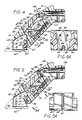
- each article securing member 24, 25 carries a retractable locking pin 62 which is biased by a spring 63 into locking position wherein the tip 65 of the pin 62 projects into one of a series of oblong apertures 67 formed in and spaced along the length of the inboard side 35 of side rail 22.
- a manual actuating mechanism in the form of a push button 70 is mounted in an opening 72 in the outboard surface 73 of each of the article securing members 24, 25.
- a toggle-like lever link 74 operatively connects the lock pin 62 and the push button 70 for disengaging the tip of the lock pin from the apertures 67 in the side rails 22 incident to the push button being depressed relative to the outer surface 73 of the article securing members 24, 25.
- the push button 70 is formed with a back 76 and a foot 77 interconnected by two downwardly and inwardly inclined surfaces 78, which form side walls to constrain the longitudinal movement of the actuating lever 74 placed therebetween. As the button 70 is pushed in from the position shown in FIG.
- the push button foot 77 slides on the floor or lower deck 80 of the buttonslide opening 72 and pivots the actuating lever 74 to raise the lock pin 62 against the bias of the spring 63 to the position shown in FIG. 5.
- the spring 63 urges the pin 62 toward its locked position with its tip 65 inserted into one of the oblong apertures 67, provided the pin 62 and aperture 67 are in alignment.
- the spring 63 also biases the actuating lever 74 downwardly which urges the push button 70 back to its normal position with its generally flat outer face substantially flush with the outboard surface of the article securing member 24, 25.
- the article securing members 24, 25 are gently curved and inclined upwardly and inwardly with respect to the z axis of the side rails and have substantially smooth outer surfaces, at least in the longitudinal central portion thereof where the outer ends of the push buttons 70 are located.
- the outer surfaces of the article securing members are substantially smooth and flush to the effects of wind, snow and rain, but the internal parts of the locking means including the actuating levers 74 and locking pins 62 are essentially shielded and protected from the elements. This substantially prevents icing and freezing up of the locking means and also substantially prevents the entry of dust and dirt therein which may cause the pins 62 and push buttons 70 to stick.
- the push buttons 70 are made of substantially non-sticking plastic materials such as Nylon, for example.
- the outer face of the push button 70 is provided with a shallow concave recess 79 for engagement by an operator's finger or thumb.
- a drainage slot 85 is provided in the underside 81 of the article securing member 24 to facilitate the draining of liquid from within button slide opening 72.
- This drainage slot substantially prevents the retaining of liquid within the button slide opening adjacent the locking pin 62 and actuating lever 74 which could possibly freeze up to prohibit the working of the locking means.
- the underside of the push button is formed with a pair of integral triangular detents 82 that project into a pair of spaced apart guide grooves 84 formed in the lower deck 80 of the button slide opening 72 formed in the article securing members 24, 25 as seen in FIG. 4A.
- a tab 86 is formed integral with the top portion of the push button 70 and projects into a guide groove 88 formed in the upper surface 89 of the push button opening 72 to prevent the accidental withdrawal of the pushbutton therefrom.
- the spring 63 is mounted on the upper end of the lock pin 62 and the lower end of the pin is inserted into the lower pin receiving hole 110 in the stanchion.
- the spring is compressed and inserted into the upper socket 111.
- the pin is lifted to expose the reduced diameter portion 99 and the key-hole end 95 of the lever link 74 is slipped over it and up to abut the annular shoulder 96.
- the radiused end 94 of the lever is lifted so the foot 77 of the button can be slid beneath it.
- the button 70 is then further inserted into the recess 72 with the lower lugs 82 first entering the lower slots 84 in the recess floor.
- the upper end of the button 70 is finally pushed in so that the upper tab 86 snaps into the upper groove 88 in the stanchion.
- the entire locking means is thus held captive in the slide opening 72.
- the pushbutton 70 is shown in more detail in Figures 6-8. These figures show the relation of the inclined side walls 78 and the two triangular detents 82 which depend therefrom and are formed integrally therewith.
- the button foot 77 and side walls 78 define a channel 90 which is closed on the outboard side by the inward face 91 of the pushbutton back 76.
- a generally U-shaped opening 92 is formed in the inboard end of the foot 77, the jaws 93 of which surround but do not engage the locking pin 62 when the pushbutton 70 is depressed so that the locking pin can move freely in the opening 92.
- the actuating lever 74 is shown in greater detail in Figures 9 and 10. As shown in these figures, the foot or pivot end 94 of the lever is bent back on itself to form a smoothly radiused edge.
- the lever 74 preferably has the shape of a lazy J, as shown in Figure 10, and a key-hole slot 95 is formed therein opposite the foot end 94.
- the slot 95 is sized to accept the locking pin 62 and to engage a shoulder 96 carried thereon.
- the lever abutting shoulder 96 on the locking pin 62 is shown in more detail in Figures 4 and 11.
- the spring 63 exerts a biasing force on the upper surface of the shoulder, while the lower surface engages the actuating lever 74.
- the actuating lever lifts pin 62 by shoulder 96 against the biasing face of the spring 63.
- the pin is comprised of sections having different radii which impedes the capillary action of liquid therealong.
- An intermediate portion 99 of the pin 62 is formed with a reduced diameter for insertion into the keyhole slot 95 which captures the pin 62 below the annular shoulder 96.
- the tip 65 of the pin 62 is covered with a plastic material which may be secured in place by injection molding a plastic end piece 97 directly on and around a raised button 98.
- each stanchion 24 is formed with a collar portion 100 having an opening therein for receiving an end of the cross bar 26, which is generally oval in cross-section.
- the cross bar 26 typically includes a relatively thin-walled metal beam portion which may be of either extruded or roll-formed construction and is formed with an upper groove for receiving a resilient insert member which extends along the length of the cross bar 26.
- a suitable fastener such as a self-tapping screw is used to secure the cross bar 26 to the collar portion 100 of the stanchion 24.
- each of the stanchions 24 also includes a pair of downwardly directed legs 102 spaced apart longitudinally with respect to the centrally located push button 70.
- a pair of article securing openings 103 are formed in the stanchions 23 between the push button 70 and the legs 102. These openings 103 are useful for receiving hooks, ropes or elastic tie down straps for securing articles to the carrier 20.
- the article securing members 25 are preferably in the form of tie-down elements mounted for longitudinal movement on the side rails 22.
- Each of the tie-down elements 25 includes an aperture 104 at its upper inner end which is similarly useful for receiving a hook, rope end or an elastic strap for securing articles or luggage in the carrier 20.
- the retractable pin locking mechanism of the tie down element 25 is generally the same as for the stanchion members 24 although the push buttons may be slightly smaller in size.
- the side rails 22 may be made of extruded aluminum or of roll-formed sheet metal, if desired, and the oblong apertures 67 are oriented so that their major axis is in a vertical plane or parallel to the y axis shown in Fig. 1A.
- two complementary round holes 105, 106 one on the inboard side 35 and one on the upper supporting surface 30 of side rail 22, can be provided as further tie down means. These holes 105, 106 can be sized to accept a rope or the J-end of a bungie cord.
- End caps 107 similar to those shown in the previously mentioned copending application Serial No. 250,705 may be provided to close the end of the rails and provide a smooth streamlined appearance thereto.
Landscapes
- Engineering & Computer Science (AREA)
- Mechanical Engineering (AREA)
- Fittings On The Vehicle Exterior For Carrying Loads, And Devices For Holding Or Mounting Articles (AREA)
- Vehicle Step Arrangements And Article Storage (AREA)
- Casings For Electric Apparatus (AREA)
Claims (17)
- Système pour porter des articles agencé pour être monté sur une surface externe de la carrosserie d'un véhicule automobile, comprenant au moins un dispositif (24) de fixation d'articles monté pour pouvoir effectuer un mouvement longitudinal sur un rail allongé (22), ledit rail comprenant une pluralité d'ouvertures (67) espacées longitudinalement, ledit dispositif (24) de fixation d'articles comprenant un élément de verrouillage (62) pouvant coopérer avec lesdites ouvertures (67) dans ledit rail (22) pour verrouiller et ajuster longitudinalement ledit dispositif (24) de fixation d'articles à des positions prédéterminées le long dudit rail, un moyen de ressort (63) poussant une extrémité de l'élément de verrouillage (62) à s'engager avec l'ouverture (67), le dispositif (24) de fixation portant un mécanisme de manoeuvre comprenant un élément d'actionnement (70) qui peut se déplacer entre une position non enfoncée de verrouillage vers une position enfoncée de déverrouillage, caractérisé en ce qu'un levier de connexion (74) connecte d'une manière opérationnelle ledit élément de verrouillage (62) et ledit élément d'actionnement (70) pour désengager ledit élément de verrouillage (62) de ladite ouverture (67) lorsque ledit élément d'actionnement (70) est enfoncé.
- Système pour porter des articles comme défini dans la revendication 1, caractérisé en ce que ledit dispositif (24) de fixation d'articles est une patte montée d'une manière coulissante sur ledit rail (22) pour supporter une extrémité d'une barre transversale (26) du système pour supporter des articles.
- Système pour porter des articles comme défini dans la revendication 1, caractérisé en ce que ledit dispositif (24) de fixation d'articles est une attache agencée pour être montée d'une manière coulissante sur ledit rail (22) et qu'il comporte au moins une ouverture (104) agencée pour recevoir une courroie de fixation.
- Système pour porter des articles comme défini dans la revendication 1, caractérisé en ce que ledit dispositif (24) de fixation d'articles est formé avec une douille interne (111) pour recevoir une extrémité dudit moyen de ressort (63) et que ledit élément de verrouillage (62) est formé avec un épaulement (96) entre ses extrémités, venant en appui contre l'autre extrémité dudit moyen de ressort (63).
- Système pour porter des articles comme défini dans la revendication 1, caractérisé en ce que ledit élément de verrouillage (62) se présente sous la forme d'une goupille allongée et généralement cylindrique ayantau moins un épaulement annulaire (96) formé entre ses extrémités et en ce que ledit levier de connexion (74) est connecté d'une manière opérationnelle à ladite goupille pour venir en appui contre ledit épaulement annulaire (96).
- Système pour porter des articles comme défini dans la revendication 5, caractérisé en ce que ledit moyen de ressort (63) s'engage avec ledit épaulement annulaire (96) sur le côté opposé à celui contre lequel vient en appui ledit levier de connexion.
- Système pour porter des articles comme défini dans la revendication 1, caractérisé en ce que ledit dispositif (24) pour fixer des articles comporte un creux s'ouvrant vers l'extérieur (72) et que ledit élément d'actionnement (70) se présente sous la forme d'un bouton-poussoir disposé d'une manière coulissante dans ledit creux (72).
- Système pour porter des articles comme défini dans la revendication 9, caractérisé en ce que ledit bouton-poussoir (70) est formé avec une poche interne pour recevoir et supporter une extrémité (94) dudit levier de connexion (74) pour pouvoir effectuer un mouvement de pivotement lorsque ledit bouton-poussoir est enfoncé.
- Système pour porter des articles comme défini dans la revendication 7, caractérisé en ce que ledit bouton (70) est formé avec au moins un ergot (82) faisant saillie vers l'extérieur, dans une direction générale perpendiculaire à l'axe du bouton (70) et du creux (72), de manière à guider le mouvement coulissant du bouton (70) dans le creux (72).
- Système pour porter des articles comme défini dans la revendication 9, caractérisé en ce que ledit bouton (70) est formé avec une paire d'ergots (82) faisant saillie vers l'extérieur, dans une direction générale perpendiculaire à sa surface de glissement inférieure et en ce que ledit creux (72) est formé avec une paire de fentes aux extrémités fermées (84) pour recevoir ladite paire d'ergots (82), afin de limiter le mouvement coulissant vers l'extérieur dudit bouton (70) par rapport audit creux (72)
- Système pour porter des articles comme défini dans la revendication 10, caractérisé en ce que lesdites fentes à extrémités fermées (84) constituent des fonds au moins partiellement ouverts pour fournir des passages de drainage hors desdits creux (72), en dessous de la surface de glissement (80) dudit bouton-poussoir.
- Système pour porter des articles comme défini dans la revendication 8, caractérisé en ce que ledit levier de connexion (74) est formé avec une extrémité avec un arrondi doux (94) coopérant avec ladite poche interne dudit bouton-poussoir (70) en étant supporté par elle.
- Système pour porter des articles comme défini dans la revendication 12, caractérisé en ce que ledit levier de connexion (74) a une extrémité (94) retournée sur elle même pour former une extrémité avec un arrondi doux, coopérant avec ladite poche interne dudit bouton-poussoir (70) en étant supporté par celle-ci.
- Système pour porter des articles comme défini dans la revendication 13, caractérisé en ce que l'autre extrémité dudit levier de connexion (74) est formée avec une ouverture ayant la forme générale d'un trou de serrure (95) ayant un trou circulaire et une fente d'entrée étroite, ladite goupille de verrouillage étant formée avec une portion de diamètre diminué (99) entre ledit épaulement annulaire (96) et ladite extrémité de verrouillage (65), ladite fente d'entrée étant dimensionnée pour recevoir ledit diamètre diminué et ledit trou circulaire étant dimensionné pour recevoir ladite section de goupille près dudit épaulement annulaire (96).
- Système pour porter des articles comme défini dans la revendication 1, caractérisé en ce que ledit élément de verrouillage (62) est formé avec une extrémité arrondie (97) non métallique.
- Système pour porter des articles comme défini dans la revendication 15, caractérisé en ce que ladite extrémité non métallique (97) est formée en un matériau plastique par injection-moulage, directement sur l'extrémité dudit élément de verrouillage (62).
- Système pour porter des articles comme défini dans la revendication 1, caractérisé en ce qu'il comprend deux rails allongés (22) agencés pour venir se monter sur la dite surface externe de la carrosserie en étant espacés et parallèles, une paire de dispositifs (24) de fixation d'articles étant montée pour pouvoir effectuer un mouvement longitudinal sur chacun desdits rails et soutenir une barre transversale (26) entre eux.
Applications Claiming Priority (3)
| Application Number | Priority Date | Filing Date | Title |
|---|---|---|---|
| US07/561,696 US5205453A (en) | 1990-08-01 | 1990-08-01 | Locking mechanism for automobile luggage racks |
| US561696 | 1990-08-01 | ||
| PCT/US1991/002965 WO1992002385A1 (fr) | 1990-08-01 | 1991-04-30 | Mecanisme de verrouillage pour galerie d'automobile |
Publications (3)
| Publication Number | Publication Date |
|---|---|
| EP0495018A1 EP0495018A1 (fr) | 1992-07-22 |
| EP0495018A4 EP0495018A4 (en) | 1993-02-03 |
| EP0495018B1 true EP0495018B1 (fr) | 1995-07-19 |
Family
ID=24243046
Family Applications (1)
| Application Number | Title | Priority Date | Filing Date |
|---|---|---|---|
| EP91909019A Expired - Lifetime EP0495018B1 (fr) | 1990-08-01 | 1991-04-30 | Mecanisme de verrouillage pour galerie d'automobile |
Country Status (12)
| Country | Link |
|---|---|
| US (2) | US5205453A (fr) |
| EP (1) | EP0495018B1 (fr) |
| JP (1) | JPH05502642A (fr) |
| KR (1) | KR950009723B1 (fr) |
| CN (1) | CN1059500A (fr) |
| AT (1) | ATE125212T1 (fr) |
| AU (1) | AU641015B2 (fr) |
| CA (1) | CA2066778C (fr) |
| DE (1) | DE69111411T2 (fr) |
| ES (1) | ES2077227T3 (fr) |
| MX (1) | MX9100434A (fr) |
| WO (1) | WO1992002385A1 (fr) |
Families Citing this family (40)
| Publication number | Priority date | Publication date | Assignee | Title |
|---|---|---|---|---|
| US5203483A (en) * | 1990-11-06 | 1993-04-20 | John A. Bott | Vehicle article carrier |
| CN1143932A (zh) * | 1994-01-26 | 1997-02-26 | 先进附件系统公司 | 载物架 |
| US5577650A (en) * | 1994-12-06 | 1996-11-26 | Advanced Accessory Systems L.L.C. | Split stanchion article carrier with pivoting thumbwheel |
| US5573161A (en) * | 1994-12-22 | 1996-11-12 | Stapleton; Craig A. | Article carrier crossbar with split stanchion clamp |
| US5732864A (en) * | 1994-12-22 | 1998-03-31 | Advanced Accessory Systems Llc | Article carrier crossbar with split stanchion clamp |
| US5794827A (en) * | 1995-12-15 | 1998-08-18 | Jac Products, Inc. | Vehicle article carrier |
| US5704524A (en) * | 1996-04-25 | 1998-01-06 | Advanced Accessory Systems Llc | Latch actuator for automoblie article carriers |
| US5762247A (en) * | 1996-05-02 | 1998-06-09 | Jac Products, Inc. | Vehicle article carrier |
| US5826766A (en) * | 1997-03-14 | 1998-10-27 | Jac Products, Inc. | Vehicle article carrier |
| US6050467A (en) * | 1997-04-03 | 2000-04-18 | Decoma International, Inc. | Article carrier assembly having a cross rail assembly adjustable within a range of infinite operating positions |
| CA2234000C (fr) * | 1997-04-03 | 2005-10-04 | Decoma International Inc. | Porte-bagages comportant un ensemble de rails transversaux reglable longitudinalement sur un cote d'un vehicule automobile |
| CA2233986C (fr) * | 1997-04-03 | 2005-11-15 | Decoma International Inc. | Porte-bagages comportant un ensemble de rails transversaux avec un mecanisme de verrouillage tournant |
| US6010048A (en) * | 1997-07-09 | 2000-01-04 | Yakima Products | Roof rack with quick release tower assembly |
| US6070774A (en) * | 1997-10-29 | 2000-06-06 | Jac Products, Inc. | Vehicle article carrier |
| USD401548S (en) | 1998-02-10 | 1998-11-24 | Jac Products, Inc. | Vehicle article carrier bracket |
| USD417186S (en) | 1998-02-11 | 1999-11-30 | Jac Products, Inc. | Vehicle article carrier bracket |
| US6158639A (en) * | 1998-04-20 | 2000-12-12 | Decoma International Inc. | Article carrier for vehicle |
| US6305589B1 (en) | 1999-03-01 | 2001-10-23 | Industri Ab Thule | Vertically engageable carrier foot |
| US6109076A (en) * | 1999-05-06 | 2000-08-29 | Master Lock Company | Automobile and airbag anti-theft device |
| FR2797455B1 (fr) * | 1999-08-11 | 2001-10-05 | Brutsaert Accessories Nv | Dispositif pour la fixation d'une marquise enroulable sur le toit d'une caravane, d'une residence mobile ou analogues |
| CA2416108A1 (fr) * | 2002-03-13 | 2003-09-13 | Jac Products, Inc. | Mecanisme de verrouillage de barre transversale d'un porte-bagages de vehicule |
| US6905053B2 (en) * | 2003-01-10 | 2005-06-14 | Watermark Paddlesports, Inc. | Rack tower |
| US7370780B2 (en) * | 2003-05-14 | 2008-05-13 | Honda Motor Co., Ltd. | Roof rack cover attachment system and method |
| US20060273123A1 (en) * | 2004-09-27 | 2006-12-07 | Settelmayer Joseph J | Rack tower assemblies and rack systems |
| NZ561811A (en) | 2007-09-21 | 2010-06-25 | Hubco Automotive Ltd | Extendable roof rack |
| NZ561809A (en) | 2007-09-21 | 2009-11-27 | Hubco Automotive Ltd | Resilient infill |
| WO2009158728A1 (fr) * | 2008-06-27 | 2009-12-30 | Yakima Products, Inc. | Dispositifs de liaison pour relier des éléments de support de galerie de véhicule à des véhicules |
| AU2013255540A1 (en) * | 2012-04-30 | 2014-12-18 | Yakima Australia Pty Limited | Retention dock |
| WO2014022435A1 (fr) | 2012-07-30 | 2014-02-06 | Yakima Innovation Development Corporation | Élément de remplissage de barre transversale à fentes en t |
| US9150159B1 (en) * | 2014-04-22 | 2015-10-06 | Ford Global Technologies, Llc | Vehicle roof rack system |
| CN104118358A (zh) * | 2014-07-16 | 2014-10-29 | 甘坚 | 一种多功能车用梯 |
| US10040403B2 (en) | 2015-06-09 | 2018-08-07 | Yakima Products, Inc. | Crossbar clamp actuator |
| AU2016344069A1 (en) * | 2015-10-27 | 2018-06-14 | Horizon Global Corporation | Load support system for vehicle roof |
| CN108327644B (zh) * | 2017-01-19 | 2023-03-14 | 福特环球技术公司 | 车顶行李架及包含其的车辆 |
| US20180215322A1 (en) * | 2017-01-31 | 2018-08-02 | Yakima Products, Inc. | Rooftop cargo carrier system |
| US10549700B2 (en) * | 2017-02-17 | 2020-02-04 | Ford Global Technologies, Llc | Pickup box adaptable side-mounted rail |
| US11433800B2 (en) | 2019-12-20 | 2022-09-06 | Jac Products, Inc. | Article carrier track system |
| CN111204273A (zh) * | 2020-01-07 | 2020-05-29 | 郑州蓝图土地环境规划设计有限公司 | 一种用于土地整治工程的检测车 |
| CN111216646B (zh) * | 2020-03-17 | 2021-11-26 | 蒙城县望槐信息科技有限责任公司 | 一种便于安装的汽车行李架 |
| CN111806350B (zh) * | 2020-07-20 | 2021-12-10 | 深圳云台映象科技有限公司 | 一种支撑结构和车辆 |
Family Cites Families (39)
| Publication number | Priority date | Publication date | Assignee | Title |
|---|---|---|---|---|
| US725577A (en) * | 1902-12-26 | 1903-04-14 | John D Miller | Sash-lock. |
| US2121531A (en) * | 1936-05-15 | 1938-06-21 | United Carr Fastener Corp | Door latch structure |
| US3227102A (en) * | 1962-04-12 | 1966-01-04 | Evans Prod Co | Freight bracing apparatus |
| FR1329943A (fr) * | 1962-07-27 | 1963-06-14 | Daimler Benz Ag | Montage d'un porte-bagages sur un toit de voiture automobile avec nervures ou saillies longitudinales |
| USRE26309E (en) * | 1963-03-20 | 1967-11-28 | Freight bracing apparatus | |
| USRE26539E (en) * | 1967-12-04 | 1969-03-04 | Luggage rack | |
| USRE26538E (en) * | 1967-12-04 | 1969-03-04 | Luggaoe rack | |
| US3554416A (en) * | 1968-02-21 | 1971-01-12 | Bott John Anthony | Vehicle luggage rack |
| US3721200A (en) * | 1971-04-02 | 1973-03-20 | Gypsum Co | Freight restraining bar |
| US3774939A (en) * | 1971-09-16 | 1973-11-27 | Union Pacific Railroad Co | Load restraining crossbar |
| US3782295A (en) * | 1972-05-09 | 1974-01-01 | United States Gypsum Co | Cargo restraining bar |
| JPS5843B2 (ja) * | 1973-12-26 | 1983-01-05 | 豊田工機株式会社 | バツクラツシホセイソウチ |
| US3912894A (en) * | 1974-04-26 | 1975-10-14 | Westinghouse Electric Corp | Convertible switch |
| US4516710A (en) * | 1974-07-08 | 1985-05-14 | Bott John Anthony | Article carrier for automotive vehicles |
| USRE32706E (en) * | 1974-07-08 | 1988-07-05 | Article carrier for automotive vehicles | |
| US3952671A (en) * | 1975-02-02 | 1976-04-27 | Transco Inc. | Universal crossbar head for engaging beltrails |
| US4132335A (en) * | 1977-09-27 | 1979-01-02 | Four Star Corporation | Slidable bracket for article carrier |
| US4225068A (en) * | 1978-09-28 | 1980-09-30 | Ingram Charles E | Luggage rack |
| US4244501A (en) * | 1979-01-18 | 1981-01-13 | Four Star Corporation | Slidable bracket for luggage rack |
| US4279368A (en) * | 1979-03-09 | 1981-07-21 | Four Star Corporation | Stanchion assembly |
| US4372469A (en) * | 1979-03-29 | 1983-02-08 | Four Star Corporation | Article carrier having variably positionable cross-rail bracket |
| US4239138A (en) * | 1979-06-11 | 1980-12-16 | Four Star Corporation | Article carrier comprising slotted side rail with slidable cross-rail and bracket therefor |
| DE2939672A1 (de) * | 1979-09-29 | 1981-04-16 | Volkswagenwerk Ag, 3180 Wolfsburg | Anordnung mit einer ein dach aufweisenden fahrzeug-karosserie und einer auf dem dach fest montierten reling |
| DE3102736A1 (de) * | 1979-09-29 | 1982-09-02 | Volkswagenwerk Ag, 3180 Wolfsburg | "anordnung mit einer ein dach aufweisenden fahrzeugkarosserie und einer auf dem dach fest montierten reling fuer einen dachgepaecktraeger" |
| US4406386A (en) * | 1981-04-06 | 1983-09-27 | Masco Corporation | Article carrier and a bracket therefor |
| US4469261A (en) * | 1982-05-06 | 1984-09-04 | Masco Corporation | Article carrier with adjustably positionable bracket |
| US4448337A (en) * | 1982-05-06 | 1984-05-15 | Masco Corporation | Article carrier |
| US4616772A (en) * | 1983-01-31 | 1986-10-14 | Mareydt Ray G | Carrier rack and stanchion |
| US4650383A (en) * | 1985-02-19 | 1987-03-17 | Hoff Phillip L | Cargo stabilizer for utility vehicles |
| US4754905A (en) * | 1985-09-20 | 1988-07-05 | Bott John Anthony | Vehicle article carrier |
| US4967945A (en) * | 1985-09-20 | 1990-11-06 | Bott John Anthony | Vehicle article carrier |
| US4899917A (en) * | 1985-09-20 | 1990-02-13 | John A. Bott | Vehicle article carrier |
| US4684048A (en) * | 1985-09-20 | 1987-08-04 | Bott John Anthony | Vehicle article carrier |
| JPH0741942B2 (ja) * | 1986-03-19 | 1995-05-10 | 日立マクセル株式会社 | テ−プ用ケ−ス |
| US5082158A (en) * | 1988-09-20 | 1992-01-21 | Bott John Anthony | Article carrier |
| DE68919476T2 (de) * | 1988-09-28 | 1995-06-14 | Mascotech Inc | Gepäckträger für fahrzeuge. |
| US4982886A (en) * | 1989-03-27 | 1991-01-08 | John A. Bott | Article carrier |
| US5007570A (en) * | 1990-04-02 | 1991-04-16 | Chrysler Corporation | Luggage rack for a vehicle |
| US5010780A (en) * | 1990-05-15 | 1991-04-30 | Plastic Industries, Inc. | Device for actuating a remotely positioned spring-biased latch |
-
1990
- 1990-08-01 US US07/561,696 patent/US5205453A/en not_active Expired - Lifetime
-
1991
- 1991-04-30 EP EP91909019A patent/EP0495018B1/fr not_active Expired - Lifetime
- 1991-04-30 CA CA002066778A patent/CA2066778C/fr not_active Expired - Fee Related
- 1991-04-30 AU AU77960/91A patent/AU641015B2/en not_active Ceased
- 1991-04-30 AT AT91909019T patent/ATE125212T1/de not_active IP Right Cessation
- 1991-04-30 KR KR1019920700717A patent/KR950009723B1/ko not_active Expired - Fee Related
- 1991-04-30 WO PCT/US1991/002965 patent/WO1992002385A1/fr not_active Ceased
- 1991-04-30 ES ES91909019T patent/ES2077227T3/es not_active Expired - Lifetime
- 1991-04-30 JP JP3508890A patent/JPH05502642A/ja active Pending
- 1991-04-30 DE DE69111411T patent/DE69111411T2/de not_active Expired - Fee Related
- 1991-07-25 CN CN91105046A patent/CN1059500A/zh active Pending
- 1991-07-30 MX MX9100434A patent/MX9100434A/es not_active IP Right Cessation
-
1993
- 1993-01-25 US US08/007,490 patent/US5326007A/en not_active Expired - Lifetime
Also Published As
| Publication number | Publication date |
|---|---|
| AU7796091A (en) | 1992-03-02 |
| AU641015B2 (en) | 1993-09-09 |
| DE69111411D1 (de) | 1995-08-24 |
| KR920702299A (ko) | 1992-09-03 |
| EP0495018A1 (fr) | 1992-07-22 |
| MX9100434A (es) | 1992-04-01 |
| CN1059500A (zh) | 1992-03-18 |
| CA2066778C (fr) | 1996-11-19 |
| KR950009723B1 (ko) | 1995-08-26 |
| CA2066778A1 (fr) | 1992-02-02 |
| DE69111411T2 (de) | 1997-04-03 |
| US5205453A (en) | 1993-04-27 |
| WO1992002385A1 (fr) | 1992-02-20 |
| US5326007A (en) | 1994-07-05 |
| EP0495018A4 (en) | 1993-02-03 |
| ATE125212T1 (de) | 1995-08-15 |
| ES2077227T3 (es) | 1995-11-16 |
| JPH05502642A (ja) | 1993-05-13 |
Similar Documents
| Publication | Publication Date | Title |
|---|---|---|
| EP0495018B1 (fr) | Mecanisme de verrouillage pour galerie d'automobile | |
| US5474217A (en) | Article carrier for automotive vehicles | |
| US5071050A (en) | Pivotable cross bar and stanchion connection | |
| EP0740620B1 (fr) | Dispositif de transport d'objets | |
| US4982886A (en) | Article carrier | |
| US4432478A (en) | Vehicle article carrier | |
| US5577649A (en) | Hinged rail article carrier | |
| US5232138A (en) | Article carrier | |
| US5133490A (en) | Article carrier | |
| US20010013528A1 (en) | Vertically engageable carrier foot | |
| US6158639A (en) | Article carrier for vehicle | |
| US5383589A (en) | Modular carrier system for elongate articles | |
| GB2122154A (en) | A locking device for locking roof racks and roof mountings on motor vehicles | |
| US6702369B2 (en) | Roof and rack assembly | |
| CA1314269C (fr) | Support d'objets pour vehicule possedant un deflecteur aerodynamique integre | |
| JPH0529960Y2 (fr) |
Legal Events
| Date | Code | Title | Description |
|---|---|---|---|
| PUAI | Public reference made under article 153(3) epc to a published international application that has entered the european phase |
Free format text: ORIGINAL CODE: 0009012 |
|
| 17P | Request for examination filed |
Effective date: 19920411 |
|
| AK | Designated contracting states |
Kind code of ref document: A1 Designated state(s): AT BE CH DE DK ES FR GB GR IT LI LU NL SE |
|
| RIN1 | Information on inventor provided before grant (corrected) |
Inventor name: CRONCE, GARY, M. Inventor name: TOWNS, MARK, C. Inventor name: STRINGER, CHARLES, E. Inventor name: SCHRINER, CHARLES, R. Inventor name: PUDNEY, RICHARD |
|
| A4 | Supplementary search report drawn up and despatched | ||
| AK | Designated contracting states |
Kind code of ref document: A4 Designated state(s): AT BE CH DE DK ES FR GB GR IT LI LU NL SE |
|
| 17Q | First examination report despatched |
Effective date: 19940331 |
|
| GRAA | (expected) grant |
Free format text: ORIGINAL CODE: 0009210 |
|
| AK | Designated contracting states |
Kind code of ref document: B1 Designated state(s): AT BE CH DE DK ES FR GB GR IT LI LU NL SE |
|
| PG25 | Lapsed in a contracting state [announced via postgrant information from national office to epo] |
Ref country code: NL Free format text: LAPSE BECAUSE OF FAILURE TO SUBMIT A TRANSLATION OF THE DESCRIPTION OR TO PAY THE FEE WITHIN THE PRESCRIBED TIME-LIMIT Effective date: 19950719 Ref country code: GR Free format text: LAPSE BECAUSE OF FAILURE TO SUBMIT A TRANSLATION OF THE DESCRIPTION OR TO PAY THE FEE WITHIN THE PRESCRIBED TIME-LIMIT Effective date: 19950719 Ref country code: DK Effective date: 19950719 Ref country code: BE Effective date: 19950719 |
|
| REF | Corresponds to: |
Ref document number: 125212 Country of ref document: AT Date of ref document: 19950815 Kind code of ref document: T |
|
| REF | Corresponds to: |
Ref document number: 69111411 Country of ref document: DE Date of ref document: 19950824 |
|
| ITF | It: translation for a ep patent filed | ||
| ET | Fr: translation filed | ||
| REG | Reference to a national code |
Ref country code: ES Ref legal event code: FG2A Ref document number: 2077227 Country of ref document: ES Kind code of ref document: T3 |
|
| RAP2 | Party data changed (patent owner data changed or rights of a patent transferred) |
Owner name: MASCOTECH, INC. |
|
| NLV1 | Nl: lapsed or annulled due to failure to fulfill the requirements of art. 29p and 29m of the patents act | ||
| PG25 | Lapsed in a contracting state [announced via postgrant information from national office to epo] |
Ref country code: LU Free format text: LAPSE BECAUSE OF NON-PAYMENT OF DUE FEES Effective date: 19960430 |
|
| PGFP | Annual fee paid to national office [announced via postgrant information from national office to epo] |
Ref country code: FR Payment date: 19960515 Year of fee payment: 6 |
|
| PGFP | Annual fee paid to national office [announced via postgrant information from national office to epo] |
Ref country code: SE Payment date: 19960517 Year of fee payment: 6 |
|
| PGFP | Annual fee paid to national office [announced via postgrant information from national office to epo] |
Ref country code: CH Payment date: 19960524 Year of fee payment: 6 |
|
| PLBE | No opposition filed within time limit |
Free format text: ORIGINAL CODE: 0009261 |
|
| STAA | Information on the status of an ep patent application or granted ep patent |
Free format text: STATUS: NO OPPOSITION FILED WITHIN TIME LIMIT |
|
| PGFP | Annual fee paid to national office [announced via postgrant information from national office to epo] |
Ref country code: ES Payment date: 19960614 Year of fee payment: 6 |
|
| 26N | No opposition filed | ||
| ITPR | It: changes in ownership of a european patent |
Owner name: CAMBIO NOME EPO;MASCOTECH INC. |
|
| PG25 | Lapsed in a contracting state [announced via postgrant information from national office to epo] |
Ref country code: LI Free format text: LAPSE BECAUSE OF NON-PAYMENT OF DUE FEES Effective date: 19970430 Ref country code: CH Free format text: LAPSE BECAUSE OF NON-PAYMENT OF DUE FEES Effective date: 19970430 |
|
| PG25 | Lapsed in a contracting state [announced via postgrant information from national office to epo] |
Ref country code: SE Effective date: 19970501 |
|
| PG25 | Lapsed in a contracting state [announced via postgrant information from national office to epo] |
Ref country code: ES Free format text: LAPSE BECAUSE OF NON-PAYMENT OF DUE FEES Effective date: 19970503 |
|
| PGFP | Annual fee paid to national office [announced via postgrant information from national office to epo] |
Ref country code: AT Payment date: 19970619 Year of fee payment: 7 |
|
| REG | Reference to a national code |
Ref country code: GB Ref legal event code: 732E |
|
| REG | Reference to a national code |
Ref country code: FR Ref legal event code: TP |
|
| REG | Reference to a national code |
Ref country code: ES Ref legal event code: PC2A |
|
| REG | Reference to a national code |
Ref country code: CH Ref legal event code: PL |
|
| PG25 | Lapsed in a contracting state [announced via postgrant information from national office to epo] |
Ref country code: FR Free format text: LAPSE BECAUSE OF NON-PAYMENT OF DUE FEES Effective date: 19971231 |
|
| EUG | Se: european patent has lapsed |
Ref document number: 91909019.1 |
|
| REG | Reference to a national code |
Ref country code: FR Ref legal event code: ST |
|
| PG25 | Lapsed in a contracting state [announced via postgrant information from national office to epo] |
Ref country code: AT Free format text: LAPSE BECAUSE OF NON-PAYMENT OF DUE FEES Effective date: 19980430 |
|
| REG | Reference to a national code |
Ref country code: ES Ref legal event code: FD2A Effective date: 19990201 |
|
| PGFP | Annual fee paid to national office [announced via postgrant information from national office to epo] |
Ref country code: GB Payment date: 20000317 Year of fee payment: 10 |
|
| PGFP | Annual fee paid to national office [announced via postgrant information from national office to epo] |
Ref country code: DE Payment date: 20000427 Year of fee payment: 10 |
|
| PG25 | Lapsed in a contracting state [announced via postgrant information from national office to epo] |
Ref country code: GB Free format text: LAPSE BECAUSE OF NON-PAYMENT OF DUE FEES Effective date: 20010430 |
|
| GBPC | Gb: european patent ceased through non-payment of renewal fee |
Effective date: 20010430 |
|
| PG25 | Lapsed in a contracting state [announced via postgrant information from national office to epo] |
Ref country code: DE Free format text: LAPSE BECAUSE OF NON-PAYMENT OF DUE FEES Effective date: 20020201 |
|
| PG25 | Lapsed in a contracting state [announced via postgrant information from national office to epo] |
Ref country code: IT Free format text: LAPSE BECAUSE OF NON-PAYMENT OF DUE FEES;WARNING: LAPSES OF ITALIAN PATENTS WITH EFFECTIVE DATE BEFORE 2007 MAY HAVE OCCURRED AT ANY TIME BEFORE 2007. THE CORRECT EFFECTIVE DATE MAY BE DIFFERENT FROM THE ONE RECORDED. Effective date: 20050430 |