EP0495409B1 - Aufblasbarer Gassack für Rückhaltesysteme in Fahrzeugen - Google Patents
Aufblasbarer Gassack für Rückhaltesysteme in Fahrzeugen Download PDFInfo
- Publication number
- EP0495409B1 EP0495409B1 EP92100340A EP92100340A EP0495409B1 EP 0495409 B1 EP0495409 B1 EP 0495409B1 EP 92100340 A EP92100340 A EP 92100340A EP 92100340 A EP92100340 A EP 92100340A EP 0495409 B1 EP0495409 B1 EP 0495409B1
- Authority
- EP
- European Patent Office
- Prior art keywords
- gas bag
- fold
- vehicle occupant
- restraining system
- seam
- Prior art date
- Legal status (The legal status is an assumption and is not a legal conclusion. Google has not performed a legal analysis and makes no representation as to the accuracy of the status listed.)
- Expired - Lifetime
Links
- 230000000452 restraining effect Effects 0.000 title claims description 12
- 239000000853 adhesive Substances 0.000 claims 1
- 230000001070 adhesive effect Effects 0.000 claims 1
- 239000007789 gas Substances 0.000 description 80
- 238000010521 absorption reaction Methods 0.000 description 5
- 230000000694 effects Effects 0.000 description 4
- 238000000034 method Methods 0.000 description 4
- 230000006835 compression Effects 0.000 description 2
- 238000007906 compression Methods 0.000 description 2
- 238000013016 damping Methods 0.000 description 2
- 238000006073 displacement reaction Methods 0.000 description 2
- 208000027418 Wounds and injury Diseases 0.000 description 1
- 238000010276 construction Methods 0.000 description 1
- 230000006378 damage Effects 0.000 description 1
- 239000004744 fabric Substances 0.000 description 1
- 208000014674 injury Diseases 0.000 description 1
- 238000009434 installation Methods 0.000 description 1
- 230000002093 peripheral effect Effects 0.000 description 1
Images

Classifications
-
- B—PERFORMING OPERATIONS; TRANSPORTING
- B60—VEHICLES IN GENERAL
- B60R—VEHICLES, VEHICLE FITTINGS, OR VEHICLE PARTS, NOT OTHERWISE PROVIDED FOR
- B60R21/00—Arrangements or fittings on vehicles for protecting or preventing injuries to occupants or pedestrians in case of accidents or other traffic risks
- B60R21/02—Occupant safety arrangements or fittings, e.g. crash pads
- B60R21/16—Inflatable occupant restraints or confinements designed to inflate upon impact or impending impact, e.g. air bags
- B60R21/23—Inflatable members
- B60R21/231—Inflatable members characterised by their shape, construction or spatial configuration
- B60R21/2334—Expansion control features
- B60R21/2342—Tear seams
-
- B—PERFORMING OPERATIONS; TRANSPORTING
- B60—VEHICLES IN GENERAL
- B60R—VEHICLES, VEHICLE FITTINGS, OR VEHICLE PARTS, NOT OTHERWISE PROVIDED FOR
- B60R21/00—Arrangements or fittings on vehicles for protecting or preventing injuries to occupants or pedestrians in case of accidents or other traffic risks
- B60R21/02—Occupant safety arrangements or fittings, e.g. crash pads
- B60R21/16—Inflatable occupant restraints or confinements designed to inflate upon impact or impending impact, e.g. air bags
- B60R21/23—Inflatable members
- B60R21/239—Inflatable members characterised by their venting means
Definitions
- the invention relates to a vehicle occupant restraint system in a vehicle, with a gas generator and an airbag inflatable by it, with a fold in the wall of the airbag, which is formed in that two superimposed wall parts are held together by a seam in the system Strength is dimensioned such that the fold tears open when a predetermined value of the gas bag internal pressure is reached, the seam extending along a dividing line separating the interior of the gas bag from the inside of the fold and the gas bag having an asymmetrical shape when fully inflated.
- Such a vehicle occupant restraint system is already known from DE-A-2 944 319.
- a first chamber is inflated in the gas bag provided.
- a second stage of a gas generator is actuated, which causes the seam to tear, so that a first and a second chamber are connected to form a common chamber with a larger volume, which is then inflated.
- the known gas bag must always be arranged approximately in the middle of the seating position of a vehicle occupant in the vehicle, since in particular in the event that only the first stage of the gas generator is actuated, the vehicle occupant thrown into the gas bag slides sideways, upwards or downwards, and could get hurt.
- a gas bag of symmetrical construction which also has two chambers connected by a tearable seam, whereby depending on the severity of the accident either only the first chamber or, if the seam is broken, the first and second chambers are inflated together will.
- This known gas bag must also be arranged approximately centrally to the seating position of the vehicle occupant in the vehicle, so that the occupant can immerse himself in the gas bag and cannot slide off it.
- the object of the invention is to improve a vehicle occupant restraint system so that it is arranged in the vehicle at a location which deviates significantly from the center of the seat position of the vehicle occupant without the gas bag being able to slide along in the event of an accident.
- the overall risk of injury to occupants is to be further reduced.
- the object is achieved in a vehicle occupant restraint system according to the preamble of claim 1 in that the gas generator generates an internal gas bag pressure in the case of restraint which reaches the predetermined value, and in that the gas bag is off-center to the seating position of a vehicle occupant is arranged and an eccentric direction of propagation of the gas bag is corrected when it unfolds by the appropriately positioned and oriented seam so that the direction of propagation points to the center of the sitting position.
- the tear seam is arranged such that when the seam is not torn, the gas bag expands essentially in the direction of ejection and, after the seam is torn open, it extends predominantly transversely to the direction of ejection, thereby reducing the rate of expansion of the gas bag.
- the gas generator causes the seam to tear open regardless of the severity of the accident.
- the direction of ejection of the airbag when it is deployed can be controlled within a relatively wide range, which means that the airbag can also be arranged in less central locations in a vehicle, and yet it is ensured that the occupant can dive into the airbag in the middle in the event of an accident and don't slide along it.
- the designer of a vehicle for example when designing a vehicle cockpit.
- one or more folds are arranged in at least one side part and / or in the peripheral part of the gas bag.
- At least one relief opening is formed in at least one of the superimposed wall parts of the fold.
- the gases from the inside of the gas bag are blocked from the way to the relief opening.
- the gas bag it is already known to design the gas bag to be partially gas-permeable, either by using a gas-permeable fabric or by providing relief openings in the wall of the gas bag.
- the controlled flow of gases from the gas bag is intended to optimize the energy absorption capacity in order to dampen the impact of the occupant on the gas bag. Since, in the initial phase of the restraint process, when the gas bag is fully inflated, the gases flow out through the wall of the gas bag, i.e.
- the relief opening is closed in the initial phase of the restraining process until a certain gas bag internal pressure is reached.
- the relief opening is only opened by tearing open the fold at a point in time when a damping effect by energy absorption in the gas bag is desired.
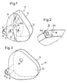
- the gas bag 10 of a restraint system for vehicles shown schematically in the almost fully inflated state in FIG. 1, is connected with its mouth opening 12 to the housing 14 of a gas generator 16.
- the airbag 10 consists of a middle jacket portion 18 and two side parts 20, 22.
- a fold 24 is formed on the side part 20 and extends almost over the entire height of the airbag.
- This fold 24 consists of two superimposed wall parts 24a, 24b.
- the fold 24 is formed in that the superimposed wall parts 24a, 24b are held against one another along a dividing line separating the interior of the gas bag from the inside of the fold.
- a seam is arranged along the dividing line 26, which can be a single or multiple seam in a quilted, warp or zigzag design.
- This seam has a precisely defined tear resistance that is tailored to the desired behavior of the gas bag.
- a relief opening 30 is formed in the wall part 24b of the fold 24. The relief opening 30 has no effect as long as the fold 24 is closed, since the gases inside the gas bag 10 remain blocked from access to the relief opening 30 as long as the inside of the fold 24 is separated from the interior of the gas bag by the seam along the dividing line 26.
- the gas bag When the gas generator 16 is activated, the gas bag is thrown out of the housing 14 and begins to unfold. In the almost completely unfolded state, it has approximately the shape shown in FIG. 1.
- the fold 24 remains closed until the gas bag internal pressure has reached a predetermined value. If the pressure inside the gas bag increases further, the seam tears along the dividing line 26, so that the fold 24 is opened. At the same time, access to the relief opening 30 is also free for the gases from the gas bag.
- the gas bag is now fully unfolded and takes on approximately the shape shown in FIG. 3. As long as it remains closed, the fold 24 on the side part 20 side shortens the extent of this side part in the exit direction of the gas bag.
- the direction of expansion of the gas bag is pivoted towards the fold 24 side. It has been found that such a fold can be used to change the direction of expansion of the gas bag by an angle of up to approximately 30 °. This value is sufficient to correct the direction of expansion of the airbag even in unfavorable installation situations so that it points approximately to the middle of the sitting position (assuming that the vehicle seat is in the middle position of the longitudinal displacement path).
- the fold 24 also shortens the entire outlet distance of the gas bag, since this fold, as long as it is closed, reduces the circumferential length of the gas bag.
- the fold 24 also reduces the exit speed of the gas bag in the final phase of its deployment. In addition to the primary aim of being able to control the outlet direction of the gas bag within a wide range, the fold 24 thus achieves two further, very desirable effects, namely a reduction in the outlet distance and a reduction in the axial outlet speed of the gas bag.
- a fourth, extremely important effect is that the relief opening 30 is controlled by the condition of the fold 24. It remains closed as long as the fold 24 is closed. No gases are lost until the gas bag is almost fully deployed.
- the gas bag has the great hardness desired in the initial phase of the restraining process.
- the relief opening 30 is only released after the fold 24 has opened and the gas bag has fully unfolded. In this phase of the restraining process, the compression path of the vehicle can be exhausted, so that energy absorption that mitigates the impact is only possible through the gas bag. This energy absorption is achieved by controlled outflow of the gases from the gas bag through the relief opening 30.
- the embodiment according to FIGS. 4 to 6 essentially differs from that according to FIGS. 1 to 3 in that the fold 24 is not arranged in a side part but on the jacket part 18. Since the fold 24 is further arranged in the lower section of the casing part 18, it causes the direction of propagation of the gas bag to be deflected downward. A relief opening is not shown in this embodiment, but can be provided if necessary.
- the fold 24 extends over the entire width of the jacket part 18. In this embodiment, too, the superimposed wall parts 24a, 24b of the fold 24 are connected by a seam along a dividing line 26.
- the superimposed wall parts of the fold are glued to one another or brought together by other suitable holding means, it only being important that these holding means are dimensioned in their strength so that the fold when a predetermined value of the gas bag internal pressure.
Landscapes
- Engineering & Computer Science (AREA)
- Mechanical Engineering (AREA)
- Air Bags (AREA)
Description
- Die Erfindung betrifft ein Fahrzeuginsassen-Rückhaltesystem in einem Fahrzeug, mit einem Gasgenerator und einem durch ihn aufblasbaren Gassack, mit einer Falte in der Wandung des Gassacks, die dadurch gebildet ist, daß zwei übereinanderliegende Wandungsteile durch eine Naht in Anlage aneinandergehalten werden, die in ihrer Festigkeit so dimensioniert ist, daß die Falte bei Erreichen eines vorbestimmten Wertes des Gassack-Innendrucks aufreißt, wobei sich die Naht entlang einer den Innenraum des Gassacks vom Inneren der Falte trennenden Trennlinie erstreckt und der Gassack in vollständig aufgeblasenem Zustand eine unsymmetrische Form aufweist.
- Ein solches Fahrzeuginsassen-Rückhaltesystem ist bereits aus der DE-A-2 944 319 bekannt. Bei leichteren Unfällen wird bei dem dabei vorgesehenen Gassack nur eine erste Kammer aufgeblasen. Bei schwereren Unfällen hingegen wird eine zweite Stufe eines Gasgenerators betätigt, der zum Reißen der Naht führt, so daß eine erste und eine zweite Kammer zu einer gemeinsamen Kammer mit größerem Volumen verbunden werden, die dann aufgeblasen wird. Der bekannte Gassack muß stets in etwa mittig zur Sitzposition eines Fahrzeuginsassen im Fahrzeug angeordnet sein, da insbesondere für den Fall, daß nur die erste Stufe des Gasgenerators betätigt wird, der in den Gassack geschleuderte Fahrzeuginsasse an diesem seitlich, nach oben oder nach unten abgleiten und sich verletzen könnte. Je nach Fahrzeugtyp kann es jedoch aufwendig sein, den Gassack mittig zur Sitzposition des Fahrzeuginsassen im Fahrzeug anzuordnen. Auch wenn der Gassack nach der DE-A-2 944 319 in aufgeblasenem Zustand unsymmetrisch ist, läßt die Gestaltung des Fahrzeug-Innenraums aus obengenanntem Grund keine Lageänderungen des Gassack-Rückhaltesystems außerhalb der Mitte der Sitzposition des Fahrzeuginsassen zu.
- Aus der DE-A-2 722 551 ist ein symmetrisch aufgebauter Gassack bekannt, welcher ebenfalls zwei mit einer aufreißbaren Naht verbundene Kammern hat, wobei je nach Schwere des Unfalls entweder nur die erste Kammer oder bei gerissener Naht die erste und die zweite Kammer zusammen aufgeblasen werden. Auch dieser bekannte Gassack muß in etwa mittig zur Sitzposition des Fahrzeuginsassen im Fahrzeug angeordnet sein, damit der Insasse mittig in den Gassack eintauchen und nicht an ihm abgleiten kann.
- Aufgabe der Erfindung ist es, ein Fahrzeuginsassen-Rückhaltesystem so zu verbessern, daß es im Fahrzeug an einem Ort angeordnet ist, welcher deutlich von der Mitte der Sitzposition des Fahrzeuginsassen abweicht, ohne daß dieser bei einem Unfall am Gassack entlanggleiten kann. Die Verletzungsgefahr für Insassen soll insgesamt weiter verringert werden.
- Die Aufgabe wird bei einem Fahrzeuginsassen-Rückhaltesystem nach dem Oberbegriff des Anspruchs 1 dadurch gelöst, daß der Gasgenerator im Rückhaltefall einen Gassack-Innendruck erzeugt, der den vorbestimmten Wert erreicht, und daß der Gassack außermittig zur Sitzposition eines Fahrzeuginsassen angeordnet ist und dabei eine außermittige Ausbreitungsrichtung des Gassacks bei seiner Entfaltung durch die entsprechend positionierte und orientierte Naht dahingehend korrigiert wird, daß die Ausbreitungsrichtung auf die Mitte der Sitzposition weist. Beim erfindungsgemäßen Rückhaltesystem ist die Reißnaht so angeordnet, daß bei nicht aufgerissener Naht eine Ausdehnung des Gassacks im wesentlichen in Ausstoßrichtung und nach dem Aufreißen der Naht eine Ausdehnung überwiegend quer zur Ausstoßrichtung erfolgt, wodurch die Ausdehnungsgeschwindigkeit des Gassacks reduziert wird. Im Gegensatz zu den Nähten bei den Gassäcken nach der DE-A-2 944 319 und DE-A-2 722 551 bewirkt der Gasgenerator unabhängig von der Unfallschwere ein Aufreißen der Naht. Durch diese Merkmale ist die Ausstoßrichtung des Gassacks bei seiner Entfaltung innerhalb eines relativ breiten Bereichs steuerbar, womit der Gassack auch an weniger zentralen Stellen in einem Fahrzeug angeordnet sein kann, und dennoch gewährleistet ist, daß der Insasse bei einem Unfall mittig in den Gassack eintauchen kann und nicht an ihm entlanggleitet. Es ergeben sich folglich für den Konstrukteur eines Fahrzeugs wesentlich mehr Konstruktionsmöglichkeiten, z.B. bei der Gestaltung eines Fahrzeugcockpits.
- Je nach der gewünschten Beeinflussung der Ausstoßrichtung wird eine oder werden mehrere Falten in wenigstens einem Seitenteil und/oder im Umfangsteil des Gassacks angeordnet.
- Gemäß einer vorteilhaften Weiterbildung der Erfindung ist vorgesehen, daß in wenigstens einem der übereinanderliegenden Wandungsteile der Falte wenigstens eine Entlastungsöffnung gebildet ist. Solange die Falte nicht aufgerissen ist, bleibt den Gasen aus dem Inneren des Gassacks der Weg zur Entlastungsöffnung versperrt. Es ist prinzipiell bereits bekannt, den Gassack teilweise gasdurchlässig auszubilden, entweder durch Verwendung eines gasdurchlässigen Gewebes oder durch Anbringen von Entlastungsöffnungen in der Wandung des Gassacks. Durch das kontrollierte Abströmen der Gase aus dem Gassack soll das Energieabsorptionsvermögen optimiert werden, um den Aufprall des Insassen auf den Gassack zu dämpfen. Da bereits in der Anfangsphase des Rückhaltevorganges bei vollständig aufgelasenem Gassack ein Ausströmen der Gase durch die Wandung des Gassacks auftritt, also zu einem Zeitpunkt, zu dem eine Energieabsorption durch den Gassack noch nicht erforderlich ist und vielmehr ein möglichst harter Gassack gewünscht wird, da eine Dämpfung des Aufpralls bereits durch die Fahrzeug-Stauchung erreicht wird, werden die vom Gasgenerator gelieferten Gase nicht optimal ausgenutzt. Bei der bevorzugten Ausführungsform des erfindungsgemäßen Gassacks ist aber die Entlastungsöffnung in der Anfangsphase des Rückhaltevorganges geschlossen, bis ein bestimmter Gassack-Innendruck erreicht ist. Die Entlastungsöffnung wird durch Aufreißen der Falte erst zu einem Zeitpunkt freigegeben, zu dem eine Dämpfungswirkung durch Energieabsorption im Gassack gewünscht wird.
- Weitere Merkmale und Vorteile der Erfindung ergeben sich aus der folgenden Beschreibung mehrerer Ausführungsformen und aus der Zeichnung, auf die Bezug genommen wird. In der Zeichnung zeigen:
- Fig. 1
- eine schematische Perspektivansicht des erfindungsgemäßen Fahrzeuginsassen-Rückhaltesystem mit einem nahezu vollständig aufgeblasenen Gassack;
- Fig. 2
- eine vergrößerte Detailansicht des in Fig. 1 gezeigten Gassacks im Schnitt entlang der Linie II-II in Fig. 1;
- Fig. 3
- eine schematische Perspektivansicht des in Fig. 1 gezeigten Gassacks in vollständig aufgeblasenem Zustand; und
- Fig. 4 bis 6
- analoge Ansichten einer anderen Ausführungsform des Gassacks.
- Der in Fig. 1 schematisch im nahezu vollständig aufgeblasenen Zustand gezeigte Gassack 10 eines Rückhaltesystems für Fahrzeuge ist mit seiner Mundöffnung 12 an das Gehäuse 14 eines Gasgenerators 16 angeschlossen. Der Gassack 10 besteht aus einem mittleren Mantelanteil 18 und zwei Seitenteilen 20, 22. An dem Seitenteil 20 ist eine Falte 24 gebildet, die sich nahezu über die gesamte Höhe des Gassacks erstreckt. Diese Falte 24 besteht aus zwei übereinanderliegenden Wandungsteilen 24a, 24b. Die Falte 24 ist dadurch gebildet, daß die übereinanderliegenden Wandungsteile 24a, 24b entlang einer den Innenraum des Gassacks vom Inneren der Falte trennenden Trennlinie in Anlage aneinandergehalten werden. Bei der gezeigten Ausführungsform ist entlang der Trennlinie 26 eine Naht angeordnet, bei der es sich um eine Einfach- oder Mehrfachnaht in Stepp-, Kett- oder Zick-Zack-Ausführung handeln kann. Diese Naht weist eine genau definierte und auf das angestrebte Verhalten des Gassacks abgestimmte Reißfestigkeit auf. Durch Bemessung der Reißfestigkeit der auf der Trennlinie 26 verlaufenden Naht wird erreicht, daß die Falte 24 bis zu einem bestimmten Wert des Gassack-Innendrucks geschlossen bleibt. In dem Wandungsteil 24b der Falte 24 ist eine Entlastungsöffnung 30 gebildet. Die Entlastungsöffnung 30 ist ohne Wirkung, solange die Falte 24 geschlossen ist, da den Gasen im Inneren des Gassacks 10 der Zutritt zur Entlastungsöffnung 30 versperrt bleibt, solange das Innere der Falte 24 durch die Naht entlang der Trennlinie 26 vom Innenraum des Gassacks abgetrennt ist.
- Bei Aktivierung des Gasgenerators 16 wird der Gassack aus dem Gehäuse 14 geschleudert und beginnt, sich zu entfalten. Im nahezu vollständig entfalteten Zustand weist er etwa die in Fig. 1 gezeigte Gestalt auf. Die Falte 24 bleibt geschlossen, bis der Gassack-Innendruck einen vorbestimmten Wert erreicht hat. Bei weiterem Druckanstieg im Inneren des Gassacks reißt die Naht entlang der Trennlinie 26 auf, so daS die Falte 24 geöffnet wird. Zugleich wird für die Gase aus dem Gassack auch der Zutritt zur Entlastungsöffnung 30 frei. Der Gassack wird nun vollständig entfaltet und nimmt etwa die in Fig. 3 gezeigte Gestalt an. Solange sie geschlossen bleibt, verkürzt die Falte 24 auf der Seite des Seitenteils 20 die Ausdehnung dieses Seitenteils in der Austrittsrichtung des Gassacks. Wenn nicht in dem gegenüberliegenden Seitenteil 22 eine gleiche Falte vorgesehen ist, wird die Ausbreitungsrichtung des Gassacks zur Seite der Falte 24 hin verschwenkt. Es wurde gefunden, daß mittels einer solchen Falte eine Änderung der Ausbreitungsrichtung des Gassacks um einen Winkel von bis zu etwa 30° erzielt werden kann. Dieser Wert reicht aus, um auch bei ungünstigen Einbausituationen die Ausbreitungsrichtung des Gassacks dahingehend zu korrigieren, daß sie etwa auf die Mitte der Sitzposition weist (wobei angenommen wird, daß der Fahrzeugsitz sich in der Mittelstellung des Längsverschiebungsweges befindet). Durch die Falte 24 wird auch eine Verkürzung der gesamten Austrittsstrecke des Gassacks erreicht, da diese Falte, solange sie geschlossen ist, die Umfangslänge des Gassacks vermindert. Bei der anschließenden Entfaltung des Gassacks in den in Fig. 3 gezeigten Zustand, nachdem die Naht entlang der Trennlinie 26 aufgerissen ist, findet nur noch eine geringe Vorwärtsverlagerung des Gassacks statt, da die Ausdehnung überwiegend quer zur Ausbreitungsrichtung erfolgt. Es ist somit ersichtlich, daß durch die Falte 24 auch die Austrittsgeschwindigkeit des Gassacks in der Endphase seiner Entfaltung vermindert wird. Neben der primär angestrebten Wirkung, die Austrittsrichtung des Gassacks innerhalb eines weiten Bereiches steuern zu können, werden durch die Falte 24 somit zwei weitere, sehr erwünschte Effekte erzielt, nämlich eine Verminderung der Austrittsstrecke und eine Verminderung der axialen Austrittsgeschwindigkeit des Gassacks.
- Ein vierter, überaus wichtiger Effekt besteht darin, daß die Entlastungsöffnung 30 durch den Zustand der Falte 24 gesteuert wird. Sie bleibt geschlossen, solange die Falte 24 geschlossen ist. Bis zur nahezu vollständigen Entfaltung des Gassacks gehen daher keine Gase verloren. Der Gassack hat die in der Anfangsphase des Rückhaltevorganges erwünschte große Härte. Erst nach Öffnung der Falte 24 und vollständiger Entfaltung des Gassacks ist die Entlastungsöffnung 30 freigegeben. In dieser Phase des Rückhaltevorgangs kann der Stauchweg des Fahrzeugs erschöpft sein, so daß eine den Aufprall mildernde Energieabsorption nur noch durch den Gassack möglich ist. Diese Energieabsorption wird durch kontrolliertes Ausströmen der Gase aus dem Gassack durch die Entlastungsöffnung 30 erzielt.
- Die Ausführungsform nach den Figuren 4 bis 6 unterscheidet sich im wesentlichen von der nach den Figuren 1 bis 3 dadurch, daß die Falte 24 nicht in einem Seitenteil, sondern am Mantelteil 18 angeordnet ist. Da die Falte 24 ferner in dem unteren Abschnitt des Mantelteils 18 angeordnet ist, bewirkt sie eine Ablenkung der Ausbreitungsrichtung des Gassacks nach unten. Eine Entlastungsöffnung ist bei dieser Ausführungsform nicht eingezeichnet, kann aber bei Bedarf vorgesehen sein. Die Falte 24 erstreckt sich über die gesamte Breite des Mantelteils 18. Auch bei dieser Ausführungsform werden die übereinanderliegenden Wandungsteile 24a, 24b der Falte 24 durch eine Naht entlang einer Trennlinie 26 verbunden.
- Bei einer weiteren, in der Zeichnung nicht dargestellten Ausführungsform sind die übereinanderliegenden Wandungsteile der Falte miteinander verklebt oder durch andere geeignete Haltemittel miteinander in Verbund gebracht, wobei es nur darauf ankommt, daß diese Haltemittel in ihrer Festigkeit so dimensioniert sind, daß die Falte bei Erreichen eines vorbestimmten Wertes des Gassack-Innendrucks aufreißt.
Claims (7)
- Fahrzeuginsassen-Rückhaltesystem in einem Fahrzeug, mit einem Gasgenerator (16) und einem durch ihn aufblasbaren Gassack (10) mit einer Falte (24) in der Wandung des Gassacks (10), die dadurch gebildet ist, daß zwei übereinanderliegende Wandungsteile (24a, 24b) durch eine Naht in Anlage aneinandergehalten werden, die in ihrer Festigkeit so dimensioniert ist, daß die Falte (24) bei Erreichen eines vorbestimmten Wertes des Gassack-Innendrucks aufreißt, wobei sich die Naht entlang einer den Innenraum des Gassacks (10) vom Inneren der Falte (24) trennenden Trennlinie (26) erstreckt und der Gassack (10) in vollständig aufgeblasenem Zustand eine unsymmetrische Form aufweist, dadurch gekennzeichnet, daß der Gasgenerator (16) im Rückhaltefall einen Gassack-Innendruck erzeugt, der den vorbestimmten Wert erreicht, und daß der Gassack außermittig zur Sitzposition eines Fahrzeuginsassen angeordnet ist und dabei eine außermittige Ausbreitungsrichtung des Gassacks (10) bei seiner Entfaltung durch die entsprechend positionierte und orientierte Naht dahingehend korrigiert wird, daß die Ausbreitungsrichtung auf die Mitte der Sitzposition weist.
- Fahrzeuginassen-Rückhaltesystem nach Anspruch 1, dadurch gekennzeichnet, daß die Haltemittel durch eine Verklebung gebildet sind.
- Fahrzeuginassen-Rückhaltesystem nach einem der vorstehenden Ansprüche, mit einem Gassack (10), der aus einem Mantelteil (18) und zwei mit diesem vernähten Seitenteilen (20, 22) besteht, dadurch gekennzeichnet, daß wenigstens eine Falte (24) im Mantelteil (18) und/oder in einem Seitenteil (20) angeordnet ist.
- Fahrzeuginassen-Rückhaltesystem nach Anspruch 3, dadurch gekennzeichnet, daß die Falte (24) sich über die gesamte Breite des Mantelteils (18) erstreckt.
- Fahrzeuginassen-Rückhaltesystem nach Anspruch 3 oder 4, dadurch gekennzeichnet, daß sich wenigstens eine Falte (24) an einem der Seitenteile (20) zumindest annähernd über die gesamte Höhe des Seitenteils (20) erstreckt.
- Fahrzeuginassen-Rückhaltesystem nach einem der vorstehenden Ansprüche, dadurch gekennzeichnet, daß in wenigstens einem der übereinanderliegenden Wandungsteile (24a, 24b) der Falte (24) wenigstens eine Entlastungsöffnung (30) gebildet ist.
- Fahrzeuginassen-Rückhaltesystem nach einem der vorstehenden Ansprüche, dadurch gekennzeichnet, daß die den Innenraum des Gassacks (10) von dem Inneren der Falte (24) trennende Trennlinie (26) quer zur Ausstoßrichtung des Gassacks (10) bei seiner Entfaltung orientiert ist.
Applications Claiming Priority (2)
| Application Number | Priority Date | Filing Date | Title |
|---|---|---|---|
| DE4101286 | 1991-01-17 | ||
| DE4101286A DE4101286A1 (de) | 1991-01-17 | 1991-01-17 | Aufblasbarer gassack fuer rueckhaltesysteme in fahrzeugen |
Publications (2)
| Publication Number | Publication Date |
|---|---|
| EP0495409A1 EP0495409A1 (de) | 1992-07-22 |
| EP0495409B1 true EP0495409B1 (de) | 1997-04-09 |
Family
ID=6423211
Family Applications (1)
| Application Number | Title | Priority Date | Filing Date |
|---|---|---|---|
| EP92100340A Expired - Lifetime EP0495409B1 (de) | 1991-01-17 | 1992-01-10 | Aufblasbarer Gassack für Rückhaltesysteme in Fahrzeugen |
Country Status (10)
| Country | Link |
|---|---|
| US (1) | US5333903A (de) |
| EP (1) | EP0495409B1 (de) |
| JP (1) | JP3060021B2 (de) |
| CN (1) | CN1063649A (de) |
| CZ (1) | CZ282317B6 (de) |
| DE (2) | DE4101286A1 (de) |
| ES (1) | ES2032738T3 (de) |
| HU (1) | HUT60198A (de) |
| PL (1) | PL293166A1 (de) |
| RU (1) | RU2041085C1 (de) |
Cited By (2)
| Publication number | Priority date | Publication date | Assignee | Title |
|---|---|---|---|---|
| DE102004058438B3 (de) * | 2004-12-03 | 2006-05-11 | Trw Automotive Gmbh | Gassack für ein Fahrzeuginsassen-Rückhaltesystem |
| DE10161956B4 (de) * | 2001-01-08 | 2015-12-31 | Trw Vehicle Safety Systems Inc. | Fahrzeuginsassenschutzvorrichtung und Fahrzeuginsassenschutzsystem |
Families Citing this family (66)
| Publication number | Priority date | Publication date | Assignee | Title |
|---|---|---|---|---|
| MX9304559A (es) * | 1992-09-01 | 1994-03-31 | Morton Int Inc | Cuerdas con costuras rascables para cojin de bolsa inflable. |
| US5308113A (en) * | 1992-10-09 | 1994-05-03 | Trw Vehicle Safety Systems Inc. | Airbag inflation-controlling member |
| US5395134A (en) * | 1993-04-02 | 1995-03-07 | Morton International, Inc. | Passenger side air bag with controlled deployment |
| DE69400970T2 (de) * | 1993-03-11 | 1997-04-10 | Morton Int Inc | Beifahrerluftsack mit gesteuerter Entfaltung |
| US5478111A (en) * | 1993-08-11 | 1995-12-26 | Morton International, Inc. | Dynamic burn vents for the cushion of an air bag module |
| WO1995006574A1 (en) * | 1993-08-31 | 1995-03-09 | Alliedsignal Inc. | Air bag with improved tear stitch pattern |
| JP3353424B2 (ja) * | 1993-11-25 | 2002-12-03 | タカタ株式会社 | エアバッグ及びエアバッグ装置 |
| JPH07205738A (ja) * | 1994-01-13 | 1995-08-08 | Toyo Tire & Rubber Co Ltd | 車両用エアバッグ |
| JP3321978B2 (ja) * | 1994-04-05 | 2002-09-09 | タカタ株式会社 | エアバッグ装置 |
| US5503429A (en) * | 1994-09-01 | 1996-04-02 | Trw Vehicle Safety Systems Inc. | Vehicle occupant restraint apparatus and method of assembly |
| DE19522765A1 (de) * | 1995-06-27 | 1997-01-02 | Pars Passive Rueckhaltesysteme | Airbagmodul |
| US5639118A (en) * | 1995-10-18 | 1997-06-17 | General Motors Corporation | Air bag module with inflation detection device |
| DE29517951U1 (de) * | 1995-11-13 | 1996-02-08 | Trw Repa Gmbh | Gassack für ein Fahrzeuginsassen-Rückhaltesystem |
| US5603526A (en) * | 1996-01-16 | 1997-02-18 | Morton International, Inc. | Pressure vent for air bag cushion |
| GB2316372B (en) * | 1996-04-01 | 2000-08-02 | Toyo Tire & Rubber Co | Airbag for front seat passenger |
| JP3769831B2 (ja) * | 1996-04-08 | 2006-04-26 | タカタ株式会社 | エアバッグ及びエアバッグ装置 |
| US5803495A (en) * | 1996-04-22 | 1998-09-08 | Autoliv Asp, Inc. | Variable volume airbag cushion |
| JP3365204B2 (ja) * | 1996-05-07 | 2003-01-08 | 豊田合成株式会社 | エアバッグ装置のエアバッグ |
| US5725244A (en) * | 1996-07-09 | 1998-03-10 | Breed Automotive Technology, Inc. | Airbag venting mechanism |
| US5704639A (en) * | 1996-07-09 | 1998-01-06 | Breed Automotive Technology, Inc. | Pressure sensitive airbag vent mechanism |
| EP0835787A1 (de) * | 1996-10-09 | 1998-04-15 | TRW Occupant Restraint Systems GmbH | Gassack für ein Fahrzeuginsassen-Rückhaltesystem |
| DE19643052A1 (de) * | 1996-10-18 | 1997-09-04 | Daimler Benz Ag | Airbag, insbesondere in einem Kraftfahrzeug |
| DE19720586C2 (de) * | 1997-05-16 | 2000-11-30 | Porsche Ag | Seitenaufprallschutzeinrichtung für einen Insassen eines Fahrzeuges |
| DE19720587A1 (de) * | 1997-05-16 | 1998-11-19 | Porsche Ag | Seitenaufprallschutzeinrichtung für einen Insassen eines Fahrzeuges |
| DE19720585A1 (de) * | 1997-05-16 | 1998-11-19 | Porsche Ag | Seitenaufprallschutzeinrichtung für einen Insassen eines Fahrzeuges |
| DE19720584C2 (de) | 1997-05-16 | 2000-11-23 | Porsche Ag | Seitenaufprallschutzeinrichtung für einen Insassen eines Fahrzeuges |
| DE29713112U1 (de) * | 1997-07-23 | 1998-01-22 | Trw Repa Gmbh | Gassack-Rückhaltesystem |
| DE29801051U1 (de) * | 1998-01-22 | 1998-05-20 | Trw Repa Gmbh | Gassack für eine Seitenaufprall-Schutzeinrichtung |
| DE29802436U1 (de) | 1998-02-12 | 1998-05-20 | Breed Automotive Technology, Inc., Lakeland, Fla. | Luftsack für ein Airbag-Modul |
| DE29804239U1 (de) * | 1998-03-10 | 1998-08-20 | TRW Occupant Restraint Systems GmbH & Co. KG, 73553 Alfdorf | Gassack für ein Fahrzeuginsassen-Rückhaltesystem |
| DE29804254U1 (de) | 1998-03-10 | 1998-07-16 | TRW Occupant Restraint Systems GmbH & Co. KG, 73553 Alfdorf | Gassack für ein Fahrzeuginsassen-Rückhaltesystem |
| DE29813081U1 (de) | 1998-07-22 | 1998-11-19 | Trw Repa Gmbh | Gassack mit Entlastungsöffnung |
| DE19903361A1 (de) * | 1999-01-28 | 2000-08-03 | Breed Automotive Tech | Verfahren zur Herstellung eines Luftsackes und Luftsack |
| US6497156B2 (en) * | 1999-12-28 | 2002-12-24 | Horiba Instruments, Inc. | Method for collecting exhaust gases |
| DE20003366U1 (de) * | 2000-02-24 | 2000-08-10 | Trw Repa Gmbh | Seitenaufprall-Schutzeinrichtung |
| US6659499B2 (en) | 2002-01-09 | 2003-12-09 | Trw Vehicle Safety Systems Inc. | Air bag with vent |
| JP4641880B2 (ja) * | 2005-07-06 | 2011-03-02 | 芦森工業株式会社 | 車両用エアバッグ |
| JP2007191103A (ja) * | 2006-01-20 | 2007-08-02 | Mazda Motor Corp | ピラーエアバッグ装置 |
| FR2900111B1 (fr) * | 2006-04-24 | 2011-02-11 | Trw Automotive Gmbh | Dispositif de retenue d'occupant de vehicule avec coussin a gaz. |
| DE102006027371A1 (de) * | 2006-06-13 | 2007-12-20 | Trw Automotive Gmbh | Aufblasbarer Gassack sowie Gassackmodul mit einem solchen Gassack |
| DE202006017996U1 (de) | 2006-11-22 | 2007-02-15 | Takata-Petri Ag | Gassack für ein Kraftfahrzeug |
| DE102007005304B4 (de) | 2007-02-02 | 2010-11-11 | Autoliv Development Ab | Gassack |
| DE102007013101A1 (de) * | 2007-03-14 | 2007-08-16 | Takata-Petri Ag | Gefalteter Gassack für ein Kraftfahrzeug |
| RU2427488C2 (ru) * | 2007-04-20 | 2011-08-27 | Аутолив Дивелопмент Аб | Подушка безопасности |
| JP2009056976A (ja) * | 2007-08-31 | 2009-03-19 | Toyoda Gosei Co Ltd | 助手席用エアバッグ |
| DE102007056137B4 (de) * | 2007-11-20 | 2015-05-13 | TAKATA Aktiengesellschaft | Gassack mit einem Einfüllstutzen und Gassackanordnung mit einem Gassack und einem Gasgenerator |
| EP2072348B1 (de) * | 2007-12-18 | 2016-10-05 | Autoliv Development AB | Knieairbag und Verfahren zum Falten davon |
| DE102008018857B3 (de) * | 2008-04-15 | 2009-07-16 | Autoliv Development Ab | Gassack |
| DE102008048398B4 (de) * | 2008-09-19 | 2019-05-23 | Joyson Safety Systems Germany Gmbh | Gassack für ein Kraftfahrzeug |
| DE102009019766A1 (de) * | 2009-04-28 | 2010-01-28 | Takata-Petri Ag | Gassack für ein Fahrzeuginsassen-Rückhaltesystem und Verfahren zum Herstellen eines Fahrzeuginsassen-Rückhaltesystems |
| US8505969B2 (en) * | 2009-10-27 | 2013-08-13 | Tk Holdings Inc. | Knee airbag module |
| JP5387479B2 (ja) * | 2010-03-30 | 2014-01-15 | 豊田合成株式会社 | エアバッグ |
| JP5822541B2 (ja) * | 2011-06-01 | 2015-11-24 | タカタ株式会社 | エアバッグの製造方法及びエアバッグ装置の製造方法 |
| JP6092861B2 (ja) * | 2011-07-12 | 2017-03-08 | ティーケー ホールディングス インク.Tk Holdings Inc. | エアバッグ |
| GB201113411D0 (en) * | 2011-08-04 | 2011-09-21 | Ford Global Tech Llc | An airbag having a pressure responsive vent |
| US20130221644A1 (en) | 2012-02-23 | 2013-08-29 | Key Safety Systems, Inc. | Airbag with multi-state vent |
| DE102013003239B4 (de) | 2013-02-27 | 2019-03-21 | Autoliv Development Ab | Knieairbag |
| JP6294952B2 (ja) * | 2013-03-15 | 2018-03-14 | オートリブ エーエスピー,インコーポレイティド | Icのための二重折りにして巻かれたクッション |
| CN103661229B (zh) * | 2013-09-17 | 2016-05-18 | 锦州锦恒汽车安全系统有限公司 | 汽车安全气囊自适应排气孔结构 |
| DE102013017695A1 (de) * | 2013-10-24 | 2014-07-24 | Daimler Ag | Airbag für einen Kraftwagen |
| EP3169554B1 (de) * | 2014-07-16 | 2018-08-15 | Takata AG | Gassack für ein fahrzeuginsassen-rückhaltesystem |
| CN104760561A (zh) * | 2015-03-24 | 2015-07-08 | 上海东方久乐汽车安全气囊有限公司 | 一种前排乘员气囊 |
| DE102017212295A1 (de) | 2017-07-18 | 2019-01-24 | Volkswagen Aktiengesellschaft | Gassack für ein Fahrzeuginsassen-Rückhaltesystem |
| DE102017217499A1 (de) * | 2017-09-29 | 2019-04-04 | Joyson Safety Systems Germany Gmbh | Gassackeinheit für ein Kraftfahrzeug |
| KR102533286B1 (ko) * | 2018-04-04 | 2023-05-17 | 현대모비스 주식회사 | 운전석용 에어백 장치 |
| DE102023202895A1 (de) * | 2023-03-29 | 2024-10-02 | Joyson Safety Systems Germany Gmbh | Gassackmodul für ein Rückhaltesystem eines Kraftfahrzeuges, Verfahren zur adaptiven Steuerung eines Gassackmoduls sowie Gassackmodulanordnung in einem Kraftfahrzeug |
Family Cites Families (10)
| Publication number | Priority date | Publication date | Assignee | Title |
|---|---|---|---|---|
| US3451693A (en) * | 1967-09-01 | 1969-06-24 | Eaton Yale & Towne | Vehicle safety method and apparatus |
| US3527475A (en) * | 1969-03-07 | 1970-09-08 | Eaton Yale & Towne | Vehicle safety system |
| DE2030863A1 (de) * | 1970-06-23 | 1971-12-30 | Klippan GmbH, 2000 Hamburg-Norderstedt | Mit einer Gaspatrone aufblasbares Luftkissen, insbesondere für Kraftfahrzeuge |
| US3797855A (en) * | 1972-04-10 | 1974-03-19 | Allied Chem | Bag deployment |
| US3810654A (en) * | 1972-05-05 | 1974-05-14 | Gen Motors Corp | Occupant restraint cushion assembly and method of manufacture |
| US3990726A (en) * | 1975-04-23 | 1976-11-09 | Nissan Motor Co., Ltd. | Inflatable and semi-crushable safety bag for vehicle passenger |
| JPS524371A (en) * | 1975-05-02 | 1977-01-13 | Shiyuusuke Wagou | Tube joint |
| DE2722551A1 (de) | 1977-05-18 | 1978-11-30 | Daimler Benz Ag | Aufblasbares aufprallschutzkissen |
| DE2944319A1 (de) * | 1979-11-02 | 1981-05-14 | Daimler-Benz Ag, 7000 Stuttgart | Aufblasbares aufprallschutzkissen |
| DE3818185C1 (de) * | 1988-05-28 | 1989-08-17 | Daimler-Benz Aktiengesellschaft, 7000 Stuttgart, De |
-
1991
- 1991-01-17 DE DE4101286A patent/DE4101286A1/de not_active Withdrawn
-
1992
- 1992-01-10 DE DE59208306T patent/DE59208306D1/de not_active Expired - Fee Related
- 1992-01-10 EP EP92100340A patent/EP0495409B1/de not_active Expired - Lifetime
- 1992-01-10 ES ES92100340T patent/ES2032738T3/es not_active Expired - Lifetime
- 1992-01-13 PL PL29316692A patent/PL293166A1/xx unknown
- 1992-01-16 HU HU9200148A patent/HUT60198A/hu unknown
- 1992-01-16 RU SU925010783A patent/RU2041085C1/ru active
- 1992-01-16 JP JP4005905A patent/JP3060021B2/ja not_active Expired - Fee Related
- 1992-01-16 CN CN92100277A patent/CN1063649A/zh active Pending
- 1992-01-17 CZ CS92147A patent/CZ282317B6/cs not_active IP Right Cessation
- 1992-01-17 US US07/822,074 patent/US5333903A/en not_active Expired - Lifetime
Cited By (2)
| Publication number | Priority date | Publication date | Assignee | Title |
|---|---|---|---|---|
| DE10161956B4 (de) * | 2001-01-08 | 2015-12-31 | Trw Vehicle Safety Systems Inc. | Fahrzeuginsassenschutzvorrichtung und Fahrzeuginsassenschutzsystem |
| DE102004058438B3 (de) * | 2004-12-03 | 2006-05-11 | Trw Automotive Gmbh | Gassack für ein Fahrzeuginsassen-Rückhaltesystem |
Also Published As
| Publication number | Publication date |
|---|---|
| JP3060021B2 (ja) | 2000-07-04 |
| JPH04306147A (ja) | 1992-10-28 |
| HUT60198A (en) | 1992-08-28 |
| ES2032738T3 (es) | 1997-06-16 |
| CZ282317B6 (cs) | 1997-06-11 |
| DE59208306D1 (de) | 1997-05-15 |
| CS14792A3 (en) | 1992-09-16 |
| HU9200148D0 (en) | 1992-04-28 |
| EP0495409A1 (de) | 1992-07-22 |
| ES2032738T1 (es) | 1993-03-01 |
| PL293166A1 (en) | 1992-09-07 |
| CN1063649A (zh) | 1992-08-19 |
| DE4101286A1 (de) | 1992-07-23 |
| US5333903A (en) | 1994-08-02 |
| RU2041085C1 (ru) | 1995-08-09 |
Similar Documents
| Publication | Publication Date | Title |
|---|---|---|
| EP0495409B1 (de) | Aufblasbarer Gassack für Rückhaltesysteme in Fahrzeugen | |
| EP0714818B1 (de) | Seitenaufprall-Gassack | |
| DE60023205T2 (de) | Luftsack | |
| DE10018170B4 (de) | Luftsackanordnung | |
| DE69406007T2 (de) | Luftsack mit aufblasbegrenzer | |
| DE19640322B4 (de) | Airbagmodul | |
| DE102004006185B4 (de) | Gassack zum Einbau in ein Kraftfahrzeug | |
| DE29517372U1 (de) | Gassack-Seitenaufprall-Schutzeinrichtung | |
| WO2008110610A1 (de) | Fahrzeugsitzanordnung und verfahren zum schützen eines fahrzeuginsassen | |
| DE60023453T2 (de) | Gasgenerator mit zwei brennkammern | |
| DE4220499C2 (de) | Aufprallschutzsystem mit Gassack (Airbag) | |
| DE102009019930A1 (de) | Gassackmodul zum Schutz des Thorax- und Kopfbereichs eines Fahrzeuginsassen | |
| WO1996025309A1 (de) | Airbagmodul | |
| DE102007013106A1 (de) | Fahrzeugsitzanordnung und Verfahren zum Schützen eines Fahrezuginsassen | |
| DE102008028389A1 (de) | Frontgassack und Ventileinrichtung | |
| DE102006038125A1 (de) | Rückhaltesystem | |
| EP1745991B1 (de) | Fahrzeuginsassen-Rückhaltesysteme mit einem Gassack | |
| DE102007026467B4 (de) | Seitenairbag mit einem in einem äußeren Gassack angeordneten Zweiten inneren Gassack | |
| DE102007057016A1 (de) | Fahrzeugsitzanordnung und Verfahren zum Schützen eines Fahrzeuginsassen | |
| DE19724625B4 (de) | Aufprallschutz | |
| EP1508485B1 (de) | Airbagmodul | |
| EP0844143B1 (de) | Gehäuse mit einer Kammer zur Aufnahme eines zusammengefalteten und aufblasbaren Luftsackes | |
| DE102006038124B4 (de) | Rückhaltesystem für ein Kraftfahrzeug | |
| EP0841226A1 (de) | Luftsack | |
| DE202022105043U1 (de) | Airbag |
Legal Events
| Date | Code | Title | Description |
|---|---|---|---|
| PUAI | Public reference made under article 153(3) epc to a published international application that has entered the european phase |
Free format text: ORIGINAL CODE: 0009012 |
|
| AK | Designated contracting states |
Kind code of ref document: A1 Designated state(s): DE ES FR GB IT SE |
|
| GBC | Gb: translation of claims filed (gb section 78(7)/1977) | ||
| EL | Fr: translation of claims filed | ||
| ITCL | It: translation for ep claims filed |
Representative=s name: DR. ING. A. RACHELI & C. |
|
| 17P | Request for examination filed |
Effective date: 19921105 |
|
| REG | Reference to a national code |
Ref country code: ES Ref legal event code: BA2A Ref document number: 2032738 Country of ref document: ES Kind code of ref document: T1 |
|
| 17Q | First examination report despatched |
Effective date: 19951002 |
|
| RAP1 | Party data changed (applicant data changed or rights of an application transferred) |
Owner name: TRW OCCUPANT RESTRAINT SYSTEMS GMBH |
|
| GRAG | Despatch of communication of intention to grant |
Free format text: ORIGINAL CODE: EPIDOS AGRA |
|
| GRAH | Despatch of communication of intention to grant a patent |
Free format text: ORIGINAL CODE: EPIDOS IGRA |
|
| GRAH | Despatch of communication of intention to grant a patent |
Free format text: ORIGINAL CODE: EPIDOS IGRA |
|
| GRAA | (expected) grant |
Free format text: ORIGINAL CODE: 0009210 |
|
| AK | Designated contracting states |
Kind code of ref document: B1 Designated state(s): DE ES FR GB IT SE |
|
| ITF | It: translation for a ep patent filed | ||
| GBT | Gb: translation of ep patent filed (gb section 77(6)(a)/1977) |
Effective date: 19970415 |
|
| REF | Corresponds to: |
Ref document number: 59208306 Country of ref document: DE Date of ref document: 19970515 |
|
| REG | Reference to a national code |
Ref country code: ES Ref legal event code: FG2A Ref document number: 2032738 Country of ref document: ES Kind code of ref document: T3 |
|
| ET | Fr: translation filed | ||
| PG25 | Lapsed in a contracting state [announced via postgrant information from national office to epo] |
Ref country code: SE Free format text: LAPSE BECAUSE OF NON-PAYMENT OF DUE FEES Effective date: 19980111 |
|
| PLBE | No opposition filed within time limit |
Free format text: ORIGINAL CODE: 0009261 |
|
| STAA | Information on the status of an ep patent application or granted ep patent |
Free format text: STATUS: NO OPPOSITION FILED WITHIN TIME LIMIT |
|
| 26N | No opposition filed | ||
| EUG | Se: european patent has lapsed |
Ref document number: 92100340.6 |
|
| PGFP | Annual fee paid to national office [announced via postgrant information from national office to epo] |
Ref country code: GB Payment date: 20001211 Year of fee payment: 10 |
|
| PGFP | Annual fee paid to national office [announced via postgrant information from national office to epo] |
Ref country code: ES Payment date: 20010123 Year of fee payment: 10 |
|
| REG | Reference to a national code |
Ref country code: GB Ref legal event code: IF02 |
|
| PG25 | Lapsed in a contracting state [announced via postgrant information from national office to epo] |
Ref country code: GB Free format text: LAPSE BECAUSE OF NON-PAYMENT OF DUE FEES Effective date: 20020110 |
|
| PG25 | Lapsed in a contracting state [announced via postgrant information from national office to epo] |
Ref country code: ES Free format text: LAPSE BECAUSE OF NON-PAYMENT OF DUE FEES Effective date: 20020111 |
|
| GBPC | Gb: european patent ceased through non-payment of renewal fee |
Effective date: 20020110 |
|
| REG | Reference to a national code |
Ref country code: ES Ref legal event code: FD2A Effective date: 20031022 |
|
| PGFP | Annual fee paid to national office [announced via postgrant information from national office to epo] |
Ref country code: FR Payment date: 20050105 Year of fee payment: 14 |
|
| PG25 | Lapsed in a contracting state [announced via postgrant information from national office to epo] |
Ref country code: FR Free format text: LAPSE BECAUSE OF NON-PAYMENT OF DUE FEES Effective date: 20060131 |
|
| PGFP | Annual fee paid to national office [announced via postgrant information from national office to epo] |
Ref country code: IT Payment date: 20060131 Year of fee payment: 15 Ref country code: DE Payment date: 20060131 Year of fee payment: 15 |
|
| REG | Reference to a national code |
Ref country code: FR Ref legal event code: ST Effective date: 20060929 |
|
| PG25 | Lapsed in a contracting state [announced via postgrant information from national office to epo] |
Ref country code: DE Free format text: LAPSE BECAUSE OF NON-PAYMENT OF DUE FEES Effective date: 20070801 |
|
| PG25 | Lapsed in a contracting state [announced via postgrant information from national office to epo] |
Ref country code: IT Free format text: LAPSE BECAUSE OF NON-PAYMENT OF DUE FEES Effective date: 20070110 |