EP0496201B1 - Tête magnétique - Google Patents
Tête magnétique Download PDFInfo
- Publication number
- EP0496201B1 EP0496201B1 EP92100138A EP92100138A EP0496201B1 EP 0496201 B1 EP0496201 B1 EP 0496201B1 EP 92100138 A EP92100138 A EP 92100138A EP 92100138 A EP92100138 A EP 92100138A EP 0496201 B1 EP0496201 B1 EP 0496201B1
- Authority
- EP
- European Patent Office
- Prior art keywords
- gap
- magnetic
- crystal
- head
- face
- Prior art date
- Legal status (The legal status is an assumption and is not a legal conclusion. Google has not performed a legal analysis and makes no representation as to the accuracy of the status listed.)
- Expired - Lifetime
Links
- 230000005291 magnetic effect Effects 0.000 title claims description 151
- 239000011521 glass Substances 0.000 claims description 57
- 239000013078 crystal Substances 0.000 claims description 55
- 229910000859 α-Fe Inorganic materials 0.000 claims description 40
- 230000005294 ferromagnetic effect Effects 0.000 claims description 31
- 239000002184 metal Substances 0.000 claims description 27
- 229910052751 metal Inorganic materials 0.000 claims description 27
- 239000000203 mixture Substances 0.000 claims description 11
- 239000000696 magnetic material Substances 0.000 claims description 7
- 239000013598 vector Substances 0.000 claims description 6
- QVGXLLKOCUKJST-UHFFFAOYSA-N atomic oxygen Chemical compound [O] QVGXLLKOCUKJST-UHFFFAOYSA-N 0.000 claims description 4
- 229910052760 oxygen Inorganic materials 0.000 claims description 4
- 239000001301 oxygen Substances 0.000 claims description 4
- 239000011162 core material Substances 0.000 description 62
- 239000010408 film Substances 0.000 description 29
- XEEYBQQBJWHFJM-UHFFFAOYSA-N Iron Chemical compound [Fe] XEEYBQQBJWHFJM-UHFFFAOYSA-N 0.000 description 17
- VYPSYNLAJGMNEJ-UHFFFAOYSA-N Silicium dioxide Chemical compound O=[Si]=O VYPSYNLAJGMNEJ-UHFFFAOYSA-N 0.000 description 6
- 230000000694 effects Effects 0.000 description 5
- UQSXHKLRYXJYBZ-UHFFFAOYSA-N iron oxide Inorganic materials [Fe]=O UQSXHKLRYXJYBZ-UHFFFAOYSA-N 0.000 description 5
- 238000000034 method Methods 0.000 description 5
- 238000010276 construction Methods 0.000 description 4
- 238000005259 measurement Methods 0.000 description 4
- 229910000702 sendust Inorganic materials 0.000 description 4
- 239000000758 substrate Substances 0.000 description 4
- 229910052681 coesite Inorganic materials 0.000 description 3
- 230000000052 comparative effect Effects 0.000 description 3
- 229910052906 cristobalite Inorganic materials 0.000 description 3
- 230000004907 flux Effects 0.000 description 3
- 239000003112 inhibitor Substances 0.000 description 3
- 238000002844 melting Methods 0.000 description 3
- 239000000377 silicon dioxide Substances 0.000 description 3
- 229910052682 stishovite Inorganic materials 0.000 description 3
- 239000010409 thin film Substances 0.000 description 3
- 238000011282 treatment Methods 0.000 description 3
- 229910052905 tridymite Inorganic materials 0.000 description 3
- 238000004804 winding Methods 0.000 description 3
- NBIIXXVUZAFLBC-UHFFFAOYSA-N Phosphoric acid Chemical compound OP(O)(O)=O NBIIXXVUZAFLBC-UHFFFAOYSA-N 0.000 description 2
- 239000002131 composite material Substances 0.000 description 2
- 238000009792 diffusion process Methods 0.000 description 2
- 238000005530 etching Methods 0.000 description 2
- 238000002474 experimental method Methods 0.000 description 2
- 238000007496 glass forming Methods 0.000 description 2
- 238000000227 grinding Methods 0.000 description 2
- 238000005304 joining Methods 0.000 description 2
- 238000004519 manufacturing process Methods 0.000 description 2
- 238000005498 polishing Methods 0.000 description 2
- 239000000843 powder Substances 0.000 description 2
- 238000004904 shortening Methods 0.000 description 2
- 229910052710 silicon Inorganic materials 0.000 description 2
- 238000001228 spectrum Methods 0.000 description 2
- 229910018125 Al-Si Inorganic materials 0.000 description 1
- 229910018520 Al—Si Inorganic materials 0.000 description 1
- BVKZGUZCCUSVTD-UHFFFAOYSA-L Carbonate Chemical compound [O-]C([O-])=O BVKZGUZCCUSVTD-UHFFFAOYSA-L 0.000 description 1
- 229910003251 Na K Inorganic materials 0.000 description 1
- 229910019142 PO4 Inorganic materials 0.000 description 1
- 230000002411 adverse Effects 0.000 description 1
- 229910000147 aluminium phosphate Inorganic materials 0.000 description 1
- 238000013459 approach Methods 0.000 description 1
- 239000011324 bead Substances 0.000 description 1
- 230000015572 biosynthetic process Effects 0.000 description 1
- 229910000011 cadmium carbonate Inorganic materials 0.000 description 1
- KOHRTFCSIQIYAE-UHFFFAOYSA-N cadmium;carbonic acid Chemical compound [Cd].OC(O)=O KOHRTFCSIQIYAE-UHFFFAOYSA-N 0.000 description 1
- ONIOAEVPMYCHKX-UHFFFAOYSA-N carbonic acid;zinc Chemical compound [Zn].OC(O)=O ONIOAEVPMYCHKX-UHFFFAOYSA-N 0.000 description 1
- 239000000919 ceramic Substances 0.000 description 1
- 229910052804 chromium Inorganic materials 0.000 description 1
- 238000007796 conventional method Methods 0.000 description 1
- 230000003247 decreasing effect Effects 0.000 description 1
- 230000006866 deterioration Effects 0.000 description 1
- 238000010586 diagram Methods 0.000 description 1
- 229910003460 diamond Inorganic materials 0.000 description 1
- 239000010432 diamond Substances 0.000 description 1
- 230000004927 fusion Effects 0.000 description 1
- 229910052742 iron Inorganic materials 0.000 description 1
- 229910052745 lead Inorganic materials 0.000 description 1
- 239000000463 material Substances 0.000 description 1
- 230000008018 melting Effects 0.000 description 1
- 238000002156 mixing Methods 0.000 description 1
- 238000010606 normalization Methods 0.000 description 1
- 230000003287 optical effect Effects 0.000 description 1
- NDLPOXTZKUMGOV-UHFFFAOYSA-N oxo(oxoferriooxy)iron hydrate Chemical compound O.O=[Fe]O[Fe]=O NDLPOXTZKUMGOV-UHFFFAOYSA-N 0.000 description 1
- 125000004430 oxygen atom Chemical group O* 0.000 description 1
- NBIIXXVUZAFLBC-UHFFFAOYSA-K phosphate Chemical compound [O-]P([O-])([O-])=O NBIIXXVUZAFLBC-UHFFFAOYSA-K 0.000 description 1
- 239000010452 phosphate Substances 0.000 description 1
- 229910052700 potassium Inorganic materials 0.000 description 1
- 238000012545 processing Methods 0.000 description 1
- 229910052708 sodium Inorganic materials 0.000 description 1
- 238000004544 sputter deposition Methods 0.000 description 1
- 239000000126 substance Substances 0.000 description 1
- 230000001629 suppression Effects 0.000 description 1
- 229910052725 zinc Inorganic materials 0.000 description 1
- 239000011667 zinc carbonate Substances 0.000 description 1
- 229910000010 zinc carbonate Inorganic materials 0.000 description 1
- 229910003145 α-Fe2O3 Inorganic materials 0.000 description 1
Images





Classifications
-
- G—PHYSICS
- G11—INFORMATION STORAGE
- G11B—INFORMATION STORAGE BASED ON RELATIVE MOVEMENT BETWEEN RECORD CARRIER AND TRANSDUCER
- G11B5/00—Recording by magnetisation or demagnetisation of a record carrier; Reproducing by magnetic means; Record carriers therefor
- G11B5/127—Structure or manufacture of heads, e.g. inductive
-
- G—PHYSICS
- G11—INFORMATION STORAGE
- G11B—INFORMATION STORAGE BASED ON RELATIVE MOVEMENT BETWEEN RECORD CARRIER AND TRANSDUCER
- G11B5/00—Recording by magnetisation or demagnetisation of a record carrier; Reproducing by magnetic means; Record carriers therefor
- G11B5/127—Structure or manufacture of heads, e.g. inductive
- G11B5/187—Structure or manufacture of the surface of the head in physical contact with, or immediately adjacent to the recording medium; Pole pieces; Gap features
- G11B5/1875—"Composite" pole pieces, i.e. poles composed in some parts of magnetic particles and in some other parts of magnetic metal layers
- G11B5/1877—"Composite" pole pieces, i.e. poles composed in some parts of magnetic particles and in some other parts of magnetic metal layers including at least one magnetic thin film
- G11B5/1878—"Composite" pole pieces, i.e. poles composed in some parts of magnetic particles and in some other parts of magnetic metal layers including at least one magnetic thin film disposed immediately adjacent to the transducing gap, e.g. "Metal-In-Gap" structure
-
- G—PHYSICS
- G11—INFORMATION STORAGE
- G11B—INFORMATION STORAGE BASED ON RELATIVE MOVEMENT BETWEEN RECORD CARRIER AND TRANSDUCER
- G11B5/00—Recording by magnetisation or demagnetisation of a record carrier; Reproducing by magnetic means; Record carriers therefor
- G11B5/127—Structure or manufacture of heads, e.g. inductive
- G11B5/187—Structure or manufacture of the surface of the head in physical contact with, or immediately adjacent to the recording medium; Pole pieces; Gap features
- G11B5/1871—Shaping or contouring of the transducing or guiding surface
- G11B5/1872—Shaping or contouring of the transducing or guiding surface for improving the form of the electrical signal transduced, e.g. compensation of "contour effect"
- G11B5/1874—Shaping or contouring of the transducing or guiding surface for improving the form of the electrical signal transduced, e.g. compensation of "contour effect" specially adapted for composite pole pieces, e.g. for avoiding "pseudo-gap"
Definitions
- This invention relates to a magnetic head for use in magnetic recording and reproducing apparatus such as a video tape recorder (VTR), a digital audio tape recorder (DAT) or a hard disk drive (HDD).
- VTR video tape recorder
- DAT digital audio tape recorder
- HDD hard disk drive
- the recording density either temporally (e.g. by broadening the frequency band) or spatially (e.g. by decreasing the track width or shortening the wavelength) are increased. Focusing now on the shortening of the wavelength, in order to perform shorter-wavelength magnetic recording, it is desirable to use magnetic media having high coercive force.
- Magnetic heads suitable for use with such high-coercivity media are required to satisfy various conditions including not only the high-frequency characteristics and high wear resistance of the magnetic core (these are the normal requirements to be satisfied by conventional magnetic heads) but also the high resistance to magnetic saturation of the neighborhood of the gap in the magnetic core where magnetic flux is concentrated during recording.
- a conventional magnetic head that is known to satisfy these requirements is of a MIG (metal-in-gap) structure which, as shown in Fig. 6, comprises a pair of magnetic core halves 1a and 1b generally that is made of a ferromagnetic oxide having good high-frequency characteristics and that are fitted with thin ferromagnetic metal films 3a and 3b of high saturation magnetic flux density in the gap-forming areas of the core halves 1a and 1b. Pair of the magnetic core halves are joined by a glass 5 which is located at near the magnetic gap.
- the magnetic head in which the interface between the ferromagnetic oxide 1a, 1b and the thin ferromagnetic metal film 3a, 3b is parallel to the gap face 4 is called as a parallel type MIG head.
- the present inventors made an experiment to find influence of the pseudo-gap.
- Two samples of the magnetic head having the construction shown in Fig. 6 were fabricated.
- One of them was sample A in which the gap-forming faces of the magnetic core halves la and 1b were defined by a ⁇ 100 ⁇ plane, the surfaces opposing to a recording medium were defined by a ⁇ 110 ⁇ plane and the magnetic path forming faces were defined by a ⁇ 110 ⁇ plane, so that the ⁇ 110> direction in the magnetic path forming face of each core half would be parallel to the gap-forming faces, and the other sample was designated B, in which the gap-forming faces of the magnetic core halves 1a and 1b were defined by a ⁇ 111 ⁇ plane, the surfaces opposing to a recording medium were defined by a ⁇ 211 ⁇ plane and the magnetic path forming faces were defined by a ⁇ 110 ⁇ plane, and the ⁇ 110> direction in the magnetic path forming face of one core half would depart from the ⁇ 110> direction in the magnetic path forming face of the other core half
- this invention is to provide a magnetic head which uses a single-crystal ferrite as the ferromagnetic oxide core material and which yet has a more effective crystal orientation in the single-crystal ferrite core portion than combination of the ⁇ 110 ⁇ plane for making the principal magnetic path and the ⁇ 100 ⁇ gap-forming plane as recommended by the aforementioned U.S. Patent 4,953,049.
- a magnetic head as laid down in claim 1 is provided for.
- a magnetic head as laid down in claim 2 is provided for.
- a magnetic head as laid down in claim 3 is provided for.
- the reaction between oxygen (O) in the glass and iron (Fe) in the ferrite of which the magnetic core halves are made is sufficiently suppressed to insure that it will cause only negligible adverse effects on the interface between each core half and the associated metallic magnetic substance, thereby minimizing the pseudo-gap.
- each of the magnetic heads according to the present invention are at least equal or superior in their effectiveness in solving the problem of "pseudo-gap" in the parallel type MIG head and improving its reproduction output.
- the magnetic head of the present invention is described below in detail.
- magnetic heads of the construction shown in Fig. 6 were fabricated in the same manner as was sample B.
- the first and second magnetic core halves 1a and 1b had such crystal orientations that their gap-forming faces were defined by a ⁇ 111 ⁇ plane, the faces opposing to a recording medium were defined by a ⁇ 211 ⁇ plane and the principal magnetic path forming faces were defined by a ⁇ 110 ⁇ plane, and the ⁇ 110> direction in the principal magnetic path forming face of one core half would depart from the ⁇ 110> direction in the principal magnetic path forming face of the other core half towards the faces opposing to a recording medium.
- a substrate film of SiO 2 serving as a pseudo-gap inhibitor was formed in a thickness of 50 [nm] between each of the first and second magnetic core halves 1a and 1b and the thin magnetic metal film 3a and 3b.
- the two magnetic core halves were joined together with various samples of glass 5 as identified by a-j. Using the thus fabricated magnetic heads, the intensity of beats in the reproduced signal were investigated.
- compositions of glass samples a-j and the intensity of beats that took place in the signal reproduced when each glass sample was used are shown in Table 2 below.
- the glass composition data in Table 2 refer to the values that do not count in the oxygen atoms in the glass.
- Glass samples a-g shown in Table 2 were each a non-borosilicate, low-melting point glass whereas samples h-j were each a borosilicate, low-melting point glass.
- the compositions of the glasses are determined as shown in the Table 2 so that the glasses have softening points in a range of 450 - 550 °C, and coefficients of thermal expansion in a range of 90 ⁇ 10 -7 to 100 ⁇ 10 -7 /°C.
- the thin magnetic metal films 3a and 3b were formed of an Fe-Al-Si base metallic magnetic material (82.55 wt% Fe, 7.11 wt% Al, 9.70 wt% Si and 0.64 wt% Cr; Hereinafter, it will be referred as Sendust) Table 2 Glass Composition (at%) and Beats Sample Pb Si Na K Zn Fe B Al Beat (dB) a 32.2 43.8 11.8 1.9 5.7 4.6 0.0 0.0 0.42 b 33.5 46.5 9.8 1.9 6.7 1.6 0.0 0.0 0.72 c 30.7 51.0 7.4 2.1 8.5 0.3 0.0 0.0 0.88 d 31.1 52.3 5.4 2.6 7.5 1.1 0.0 0.0 0.66 e 36.9 47.0 3.9 2.1 7.1 3.0 0.0 0.0 0.45 f 32.5 48.1 9.5 2.2 7.7 0.0 0.0 0.0 1.24 g 28.1 42.8 8.9 2.1 9.0 9.6 0.0 0.0 0.38 h 27.6 29.5
- the fusing temperature is too low to have a certain area filled with the glass, the fusing temperature is risen, the glass will then spread excessively so that the greater part of the coil winding slot is filled with the glass.
- Another disadvantage of a higher Fe content of the glass is that its fusion temperature will increase to cause deterioration in the suppression of the pseudo-gap. Therefore, by using a fused glass that has an Fe content in the range of 2-13 at%, preferably 4-13 at%, magnetic heads producing small beats in the reproduction output can be manufactured with good yield.
- the magnetic head having the construction shown in Fig. 6 produced smaller beats in the reproduction output when it used glass 5 having the Fe content within the range of 2-13 at%; a probable reason for this effect is that the mutual diffusion of oxygen (O) in the glass and iron (Fe) in the ferrite was sufficiently suppressed to insure that the substrate film would act effectively as a pseudo-gap inhibitor.
- the magnetic head was capable of reproducing as high output as head sample B (see Table 1) no matter which of glass samples a-j was employed.
- the first and second magnetic core halves 1a and 1b in the magnetic head of the construction shown in Fig. 6 had such crystallographic orientations that their gap-forming faces were defined by a ⁇ 111 ⁇ plane, the faces opposing to a recording medium were defined by a ⁇ 211 ⁇ plane and the principal magnetic path forming faces were defined by a ⁇ 110 ⁇ plane, and the ⁇ 110> direction in the principal magnetic path forming face of one core half would depart from the ⁇ 110> direction in the principal magnetic path forming face of the other core half towards the faces opposing to a recording medium.
- the glass 5 had an Fe content in the range of 2-13 at%, preferably 4-13 at%. Having these features, the magnetic head according to the embodiment produces smaller beats in the reproduction output due to the pseudo-gap while, at the same time, it yields a satisfactorily high reproduction output.
- the glass 5 which has the Fe content in the above discussed range effectively suppresses the cross-diffusion of oxygen (O) in the glass and iron (Fe) in the ferrite to thereby reduce the intensity of beats that occur in the reproduction output dueto the pseudo-gap.
- the first and second magnetic core halves la and 1b may have different crystal orientations than those specified for the embodiment described above. Even in that case, by using the glass 5 having an Fe content of the range 2-13 at%, the occurrence of beats in the reproduction output due to the pseudo-gap can be sufficiently suppressed without lowering said output.
- the thin ferromagnetic metal film 3 may be formed in such a way that both of magnetic core halves la and 1b make indirect contact with the glass 5. Even with this type of magnetic head, that the thin magnetic metal film 3a which is coated on the lateral side of the first magnetic core halves la and 1b have no continuity in the crystalline structure of the metal film and the glass will pass through the discontinuity to reach the ferrite. Thus, by using the glass 5 which has an Fe content in the range of 2-13 at%, the occurrence of beats in the reproduction output due to the pseudo-gap can be suppressed.
- the desired glass was prepared by a process that consisted of metering a non-magnetic ferrite (e.g., Zn ferrite or Cd ferrite) in an amount that wold provide a fused glass composition having an Fe content of 2-13 at%, mixing that amount of non-magnetic ferrite with the other glass-forming components and melting the mixture.
- a non-magnetic ferrite e.g., Zn ferrite or Cd ferrite
- the non-magnetic ferrite is used because if a magnetized or high-permeability glass material were present in the neighborhood of the gap, there would occur shorting of magnetic flux around the gap, whereby the performance of the magnetic head is deteriorated.
- the non-magnetic ferrite is used in order to avoid this phenomenon.
- the non-magnetic ferrite can be incorporated in the glass 5 by other methods than that described above.
- a non-magnetic ferrite forming oxide e.g., ZnO or CdO
- carbonate e.g, ZnCO 3 or CdCO 3
- ferric oxide ⁇ -Fe 2 O 3
- a glass former without the non-magnetic ferrite is melted to form glass, which is then ground in to a powder and mixed with a powder of the non-magnetic ferrite, with the mixture being then melted to form glass.
- the present inventors fabricated samples of parallel type MIG head that had a ferromagnetic oxide core portion made of a single-crystal ferrite having the various crystal orientations shown in Table 3 and that had the general appearance and cross-sectional shape shown in Figs. 6 and 8, respectively.
- the specifications of head fabrication are shown in Table 4.
- the beats in the frequency characteristic curve hereunder referred to as "Frequency characteristic beats" due to the pseudo-gap problem and the reproduction output were measured and the results were as shown in Table 5.
- Table 3 Sample No.
- the gap-forming face 101 means a face that is parallel to the face at which the thin ferromagnetic metal film 3a or 3b fitted to one magnetic core half in the MIG head abuts against the other magnetic core half with a non-magnetic material being interposed;
- the principal magnetic path forming face 103 means a face that includes the shortest magnetic path surrounding the coil winding opening in the head and that is perpendicular to the above-defined gap-forming face 101;
- the surface opposite to recording medium 102 means a face that is perpendicular to both the gap-forming face 101 and the principal magnetic path forming face 103.
- the principal magnetic path forming face 103, the gap-forming face 101 and the face 102 opposite to recording medium cross one another at right angles, so if the crystal orientations of any two of those faces are determined, the crystal orientation of the other face will be automatically determined.
- the crystal orientations shown in Table 3 for sample No. 5 are those recommended by aforementioned U.S. Patent and they are intended as a reference for comparison with the samples of the present invention.
- crystal orientations listed for sample Nos. 1-4 in Table 3 may occur in two possible combinations depending upon the location of the crystal axis in a ⁇ 110 ⁇ plane that defines the gap-forming face 101 or the face 102 opposite to recording medium. However, there is no need to distinguish them from each other since they are equivalent in consideration of symmetricality with respect to the magnetic path passing through the gap-forming face 101 and the surface 102 opposite to recording medium.
- the frequency characteristic beat and reproduction output data shown in Table 5 were measured with an iron oxide tape (coercivity: 900 Oe) as a recording medium being run at a speed of 5.8 m/sec relative to the bead.
- a frequency sweep signal was recorded at 0.1 - 10 MHz and the reproduction output was detected with a spectrum analyzer to provide a frequency characteristic curve as shown in Fig. 7; thereafter, the peak to peak output ratio was obtained in the frequency range of 3-7 MHz.
- a sine-wave signal was recorded without bias at 1, 5 and 8 MHz and a maximum output was determined from the resulting reproduction output to recording current curve.
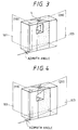
- the data in Table 5 may be interpreted as follows. If the values for sample Nos. 1-4 are compared with reference to sample No. 5, the frequency characteristic beats for sample Nos. 1-4 are greater by a degree of ca. 0.5-1 dB but their absolute values are not greater than 1.5 dB which is a practically acceptable level. Sample Nos. 1-4 produced outputs that were ca. 1-3 dB greater than the output of sample No. 5 over the low to high frequency range and a particularly high output was produced from sample No. 4. In short, sample Nos. 1-4 were comparable or superior to sample No. 5 in terms of both the effectiveness in solving the pseudo-gap problem and the reproduction output. Particularly good results were attained by sample No. 4. The general appearances of the magnetic heads corresponding to sample Nos. 1-4 are shown in perspective in Figs. 1-4, respectively.
- the present inventors extracted the following conclusion which describes the essence of the present invention in connection with a magnetic head that comprises a pair of magnetic core halves made of a single-crystal ferrite, at least one of the magnetic core halves having a thin ferromagnetic metal film formed on the gap-forming face, and the thin ferromagnetic metal film abutting against the other magnetic core half with a non-magnetic material being interposed to form a magnetic gap: "if the crystal orientations of the magnetic core half or halves on which the thin ferromagnetic film is formed are set in either one of the manners specified in Table 1 for sample Nos. 1-4, particularly No. 4, better results are obtained in terms of both the effectiveness in solving the pseudo-gap problem and the reproduction output, as compared to sample No. 5 which adopted as a reference the conditions recommended by the aforementioned U.S Patent.”
- the present inventor fabricated other samples of parallel type MIG head that had a ferromagnetic oxide core portion made of a single-crystal ferrite having the various crystal orientations shown in Table 6.
- the specifications of head fabrication were as shown in Table 4.
- the glass example A shown in Table 2 is used as a fused glass for joining the magnetic core halves.
- the frequency characteristic beats due to the pseudo-gap problem and the reproduction output were measured and the results were as shown in Table 6.
- Sample No. 7 shown in Table 6 had the crystal orientations recommended by the aforementioned U.S. Patent and will serve as a reference for comparison with sample Nos. 1-6 fabricated in accordance with the present invention.
- Table 6 Sample No. Principal magnetic path forming face Gap-forming face Surface opposite to recording medium ⁇ (deg) Freq.
- sample No. 1 shown in Table 6 the orientations of the principal magnetic path forming face and the surface opposite to recording medium were exchanged with reference to the crystal orientations widely used in single-crystal ferrite heads for VTRs, i.e., a ⁇ 110 ⁇ plane for the principal magnetic path forming face, a ⁇ 111 ⁇ plane for the gap-forming face, and a ⁇ 211 ⁇ plane for the surface opposite to recording medium.
- sample Nos. 2-6 shown in Table 4 the principal magnetic path forming face was fixed at the ⁇ 211 ⁇ plane as in sample No. 1 whereas the gap-forming face and the surface opposite to recording medium were changed to other principal crystal planes having the smallest possible Miller indices.
- the principal magnetic path forming face, the gap-forming face and the surface opposite to recording medium are denoted by the same Miller indices for sample Nos. 2 and 6, so are for sample Nos. 3 and 5.
- the faces or surfaces denoted by the same Miller indices are by no means equivalent to each other.
- the frequency characteristic beat and reproduction output data shown in Table 6 were measured with an iron oxide tape (coercivity: 900 Oe) as a recording medium being at a speed of 5.8 m/sec relative to the head.
- a frequency sweep signal was recorded at 0.1 - 10 MHz and the reproduction output was detected with a spectrum analyzer to provide a frequency characteristic curve as shown in Fig. 7; thereafter, the peak-to-peak output ratio was determined in the frequency range of 3 - 7 MHz.
- a sine-wave signal was recorded without bias at 5 MHz and a maximum output was determined from the resulting reproduction output vs recording current curve, followed by normalization with the value for comparative sample No. 7.
- the data in Table 6 may be interpreted as follows.
- the frequency characteristic beats from sample Nos. 1 - 3 are smaller than those from sample Nos. 4 - 6 but are definitely greater than those from comparative sample No. 7.
- the permissible upper level of frequency characteristic beats is approximately 2 dB
- the permissible upper level of frequency characteristic beats is approximately 1 dB
- the frequency characteristic beats of such a magnitude as produced from sample Nos. 1 - 3 will cause no significant problems in practical applications.
- sample Nos. 1 - 3 As regards the reproduction output, sample Nos. 1 - 3, as well as 5 and 6 produce obviously higher outputs than comparative sample No. 7, with a particularly high output being produced from sample No. 1.
- the present inventor extracted the following conclusion which also describes the essence of the present invention in connection with a magnetic head that comprises a pair of magnetic core halves made of a single-crystal ferrite, at least one of the magnetic core halves having a thin ferromagnetic metal film formed on the gap-forming face, and the thin ferromagnetic metal film abutting against the other magnetic core half with a non-magnetic material being interposed to form a magnetic gap: "if the crystal orientations of the magnetic core half or halves on which the thin ferromagnetic film is formed are set in either one of the manners specified in Table 6 for sample Nos. 1 - 3, better results are obtained in terms of both the effectiveness in solving the pseudo-gap problem and the reproduction output, as compared to sample No. 7 which adopted as a reference the conditions recommended by the aforementioned U.S. Patent.”
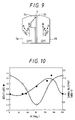
- the present inventors plotted the frequency characteristic beat and reproduction output data of Table 6 against the angle ⁇ to construct curves as shown in Fig. 10. Based on those curves, as taken together with the continuity of physical quantities, the present inventors estimated that if ⁇ were set within the range of 0 - 60° or 150 - 180°, the overall rating of the frequency characteristic beats and reproduction output would be at least comparable to the characteristics obtained with sample Nos. 1 - 3.
- the above-discussed effect which is characteristic of the present invention does not reflect the synergism due to the sameness of crystal orientations of the single-crystal ferrites which constitute the two core halves but that it would be attributable to the superposition of the effects as achieved by the individual core halves. Therefore, even in the case where the single-crystal ferrites constituting the two core halves have different crystallographic orientations, the concept of the present invention needs only to be applied to at least one core half and this should be sufficient to provide the result that is the superposition of the effect on that core half which is unique to the present invention, as added to the characteristics of the other core half.
- the MIG head to which the present invention can be applied is in no way limited to the head having the general appearance shown in Fig. 6; it may also be applied to heads having various structures of the surface opposite to a recording medium as shown in Figs. 5A to 5D.
- Fig. 5A shows an MIG head having a thin ferromagnetic metal film 3a formed on only one core half 1a;
- Fig. 5B shows an MIG head having two thin ferromagnetic metal films 3a and 3b of different thickness formed on core halves 1a and 1b on opposite sides;
- Fig. 5A shows an MIG head having a thin ferromagnetic metal film 3a formed on only one core half 1a;
- Fig. 5B shows an MIG head having two thin ferromagnetic metal films 3a and 3b of different thickness formed on core halves 1a and 1b on opposite sides;
- FIG. 5C shows an MIG head in which the interface between the ferrite core portion of a core half 1a or 1b and a thin ferromagnetic metal film 3a or 3b is not parallel to the abutting surfaces of a magnetic gap 4 and Fig. 5D shows an MIG head in which the thin ferromagnetic metal film 3 may be formed in such a way that both of magnetic core halves 1a and 1b make indirect contact with the glass 5.
- Figs. 12A and 12B show MIG composite type of the magnetic head, for use in HDD, according to the present invention.
- reference numeral 51 defines a ceramic slider; 52, a mold glass; 53, Mn-Zn ferrites halves; 54, bonding glass; 55, Sendust films; and 56, magnetic gap.
- FIGs. 12C and 12D show MIG monolithic type of the magnetic head, for use in HDD, according to the invention.
- reference numeral 61 defines a portion use for both slider and ferrite core; 62, ferrite; 63, Sendust film; 64, bonding glass; and 65, magnetic gap.
- each of the magnetic heads according to the present invention is at least equal or superior in their effectiveness in solving the problem of "pseudo-gap" in the parallel type MIG head and improving its reproduction output.
Landscapes
- Engineering & Computer Science (AREA)
- Manufacturing & Machinery (AREA)
- Magnetic Heads (AREA)
Claims (5)
- Tête magnétique comprenant deux moitiés de noyau magnétique (1a, 1b) en ferrite monocristallin attachées l'une à l'autre de manière à ce que des faces (101) formant entrefer desdites moitiés de noyau magnétique se trouvent opposées l'une à l'autre afin de former un entrefer (4) entre eux,au moins une desdites moitiés de noyau (1a, 1b) ayant une couche mince en métal ferromagnétique (3a, 3b) disposée sur ladite face (101) formant entrefer et un matériau non-magnétique (5) prévu dans ledit entrefer (4),tête dans laquelle (a) une face (102) opposée à un support d'enregistrement qui, lorsque la tête est en marche, fait face à un support d'enregistrement, (b) un plan principal de chemin magnétique (103) qui, lorsque la tête est en marche, renferme le chemin magnétique principal, et (c) lesdites faces (101) formant entrefer, sont mutuellement perpendiculaires les unes aux autres,caractérisé en ce que ladite au moins une moitié de noyau (1a, 1b) pourvue de ladite couche mince en métal ferromagnétique (3a, 3b) a une orientation cristalline dudit ferrite monocristallin de manière à ce que ledit plan principal de chemin magnétique (103) coïncide avec le plan cristallin {211} et qu'un vecteur A qui est contenu dans ledit plan principal de chemin magnétique (103) et qui est parallèle à l'axe cristallin <110> et dirigé à l'écart de ladite face (101) formant entrefer fait un angle θ dans la plage 0° - 60° ou 150° - 180° avec un vecteur B qui est parallèle à l'intersection dudit plan principal de chemin magnétique (103) et ladite face (101) formant entrefer et dirigé vers ladite face (102) opposée au support d'enregistrement.
- Tête magnétique comprenant deux moitiés de noyau magnétique (1a, 1b) en ferrite monocristallin attachées l'une à l'autre de manière à ce que des faces (101) formant entrefer desdites moitiés de noyau magnétique se trouvent opposées l'une à l'autre afin de former un entrefer (4) entre eux,au moins une desdites moitiés de noyau (1a, 1b) ayant une couche mince en métal ferromagnétique (3a, 3b) disposée sur ladite face (101) formant entrefer et un matériau non-magnétique (5) prévu dans ledit entrefer (4),tête dans laquelle (a) une face (102) opposée à un support d'enregistrement qui, lorsque la tête est en marche, fait face à un support d'enregistrement, (b) un plan principal de chemin magnétique (103) qui, lorsque la tête est en marche, renferme le chemin magnétique principal, et (c) lesdites faces (101) formant entrefer, sont mutuellement perpendiculaires les unes aux autres,caractérisé en ce que ladite au moins une moitié de noyau (1a, 1b) pourvue de ladite couche mince en métal ferromagnétique (3a, 3b) a une orientation cristalline dudit ferrite monocristallin de manière à ce que ledit plan principal de chemin magnétique (103) coïncide avec le plan cristallin {211} et ladite face (101) formant entrefer coïncide avec un plan cristallin {111} ou un plan cristallin {110}.
- Tête magnétique comprenant deux moitiés de noyau magnétique (1a, 1b) en ferrite monocristallin attachées l'une à l'autre de manière à ce que des faces (101) formant entrefer desdites moitiés de noyau magnétique se trouvent opposées l'une à l'autre afin de former un entrefer (4) entre eux,au moins une desdites moitiés de noyau (1a, 1b) ayant une couche mince en métal ferromagnétique (3a, 3b) disposée sur ladite face (101) formant entrefer et un matériau non-magnétique (5) prévu dans ledit entrefer (4),tête dans laquelle (a) une face (102) opposée à un support d'enregistrement qui, lorsque la tête est en marche, fait face à un support d'enregistrement, (b) un plan principal de chemin magnétique (103) qui, lorsque la tête est en marche, renferme le chemin magnétique principal, et (c) lesdites faces (101) formant entrefer, sont mutuellement perpendiculaires les unes aux autres,caractérisé en ce que ladite au moins une moitié de noyau (1a, 1b) pourvue de ladite couche mince en métal ferromagnétique (3a, 3b) a une orientation cristalline dudit ferrite monocristallin de manière à ce que ledit plan principal de chemin magnétique (103) coïncide avec un plan cristallin {111} et ladite face (101) formant entrefer coïncide avec un plan cristallin {110} ou un plan cristallin {211}.
- Tête magnétique selon la revendication 1 à 3, dans laquelle lesdites moitiés de noyau magnétique (1a, 1b) sont attachées l'une à l'autre par du verre (5) disposé à proximité dudit entrefer magnétique (4), ledit entrefer magnétique (4) étant parallèle à l'interface entre ladite au moins une moitié de noyau magnétique (1a, 1b) et ladite couche mince en métal ferromagnétique (3a, 3b), ledit verre ayant une teneur en Fe dans la plage 2 - 13 at % de la composition de verre à l'exception de l'oxygène.
- Tête magnétique selon la revendication 4, dans laquelle ledit verre (5) a un point de ramollissement dans la plage 450°C - 550°C.
Applications Claiming Priority (6)
| Application Number | Priority Date | Filing Date | Title |
|---|---|---|---|
| JP587/91 | 1991-01-08 | ||
| JP3000587A JPH0827903B2 (ja) | 1991-01-08 | 1991-01-08 | 磁気ヘッド |
| JP3079898A JPH04313803A (ja) | 1991-04-12 | 1991-04-12 | 磁気ヘッド |
| JP79898/91 | 1991-04-12 | ||
| JP3257974A JPH0778854B2 (ja) | 1991-10-04 | 1991-10-04 | 磁気ヘッド |
| JP257974/91 | 1991-10-04 |
Publications (2)
| Publication Number | Publication Date |
|---|---|
| EP0496201A1 EP0496201A1 (fr) | 1992-07-29 |
| EP0496201B1 true EP0496201B1 (fr) | 1996-10-30 |
Family
ID=27274528
Family Applications (1)
| Application Number | Title | Priority Date | Filing Date |
|---|---|---|---|
| EP92100138A Expired - Lifetime EP0496201B1 (fr) | 1991-01-08 | 1992-01-07 | Tête magnétique |
Country Status (5)
| Country | Link |
|---|---|
| US (1) | US5218500A (fr) |
| EP (1) | EP0496201B1 (fr) |
| KR (1) | KR100242036B1 (fr) |
| CA (1) | CA2058656A1 (fr) |
| DE (1) | DE69214847T2 (fr) |
Families Citing this family (10)
| Publication number | Priority date | Publication date | Assignee | Title |
|---|---|---|---|---|
| JPH05197903A (ja) * | 1991-10-28 | 1993-08-06 | Canon Inc | 光磁気記録装置 |
| JPH05217107A (ja) * | 1992-01-31 | 1993-08-27 | Sony Corp | 磁気ヘッド |
| EP0940803B1 (fr) * | 1993-05-31 | 2002-11-27 | TDK Corporation | Méthode d'enregistrement/reproduction magnétique |
| US5392169A (en) * | 1993-06-08 | 1995-02-21 | International Business Machines Corporation | Electrical means to diminish read-back signal waveform distortion in recording heads |
| KR100385126B1 (ko) * | 1994-10-31 | 2003-08-09 | 소니 가부시끼 가이샤 | 자기헤드 |
| JP3462019B2 (ja) * | 1996-10-23 | 2003-11-05 | アルプス電気株式会社 | 磁気ヘッド |
| JPH10162308A (ja) * | 1996-11-29 | 1998-06-19 | Alps Electric Co Ltd | 磁気ヘッド |
| JP3517067B2 (ja) * | 1996-11-29 | 2004-04-05 | アルプス電気株式会社 | 磁気ヘッド |
| JPH10188212A (ja) * | 1996-12-25 | 1998-07-21 | Sony Corp | 磁気ヘッド |
| JP2001118212A (ja) | 1999-10-14 | 2001-04-27 | Matsushita Electric Ind Co Ltd | 磁気ヘッドおよび磁気記録再生装置 |
Family Cites Families (9)
| Publication number | Priority date | Publication date | Assignee | Title |
|---|---|---|---|---|
| JPS5496012A (en) * | 1978-01-13 | 1979-07-30 | Victor Co Of Japan Ltd | Magnetic head |
| JPS55125519A (en) * | 1979-03-23 | 1980-09-27 | Hitachi Ltd | Magnetic head |
| JPS56163518A (en) * | 1980-05-16 | 1981-12-16 | Hitachi Ltd | Magnetic head |
| JPS60224109A (ja) * | 1984-04-20 | 1985-11-08 | Hitachi Ltd | 複合型磁気ヘツドを用いた磁気記録再生装置 |
| JP2781849B2 (ja) * | 1987-07-14 | 1998-07-30 | 三洋電機株式会社 | 磁気ヘッド及びその製造方法 |
| JP2551014B2 (ja) * | 1987-07-21 | 1996-11-06 | ソニー株式会社 | 複合磁気ヘッド |
| JPH0827901B2 (ja) * | 1988-10-05 | 1996-03-21 | シャープ株式会社 | 磁気ヘッド |
| JPH0730465B2 (ja) * | 1989-01-09 | 1995-04-05 | 日本碍子株式会社 | 負圧形磁気ヘッドスライダ及びその製造方法 |
| JP2941886B2 (ja) * | 1990-04-24 | 1999-08-30 | キヤノン電子株式会社 | 磁気ヘッド |
-
1991
- 1991-12-27 KR KR1019910024721A patent/KR100242036B1/ko not_active Expired - Fee Related
- 1991-12-31 US US07/813,751 patent/US5218500A/en not_active Expired - Fee Related
- 1991-12-31 CA CA002058656A patent/CA2058656A1/fr not_active Abandoned
-
1992
- 1992-01-07 EP EP92100138A patent/EP0496201B1/fr not_active Expired - Lifetime
- 1992-01-07 DE DE69214847T patent/DE69214847T2/de not_active Expired - Fee Related
Also Published As
| Publication number | Publication date |
|---|---|
| US5218500A (en) | 1993-06-08 |
| KR100242036B1 (ko) | 2000-02-01 |
| KR920015275A (ko) | 1992-08-26 |
| CA2058656A1 (fr) | 1992-07-09 |
| DE69214847T2 (de) | 1997-04-03 |
| EP0496201A1 (fr) | 1992-07-29 |
| DE69214847D1 (de) | 1996-12-05 |
Similar Documents
| Publication | Publication Date | Title |
|---|---|---|
| US4559572A (en) | Magnetic head and method of fabricating same | |
| US5270894A (en) | MIG magnetic head structured to minimize pseudo-gap problem | |
| JPS6218968B2 (fr) | ||
| JPH0157408B2 (fr) | ||
| US5218500A (en) | Magnetic head having a single-crystal ferrite core | |
| JP2513232B2 (ja) | 複合磁気ヘッド | |
| JP2624101B2 (ja) | 複合型磁気ヘッド | |
| JP3104185B2 (ja) | 磁気ヘッド | |
| JP2570305B2 (ja) | 磁気ヘッド | |
| JPH03160608A (ja) | 磁気ヘッドおよびこれを用いた磁気ヘッド装置 | |
| JP2954784B2 (ja) | 磁気ヘッド及びその製造方法 | |
| JPH0422282B2 (fr) | ||
| JPH0312805A (ja) | 磁気ヘッド及びその製造方法 | |
| JPH0542727B2 (fr) | ||
| EP0851410A2 (fr) | Tête magnétique | |
| CA2007688A1 (fr) | Tete magnetique | |
| JPH03113812A (ja) | 複合形磁気ヘツド | |
| JPH0424765B2 (fr) | ||
| JPH06103513A (ja) | 複合型磁気ヘッド | |
| JPH04283405A (ja) | 浮上型複合磁気ヘッド | |
| JPH0673165B2 (ja) | 磁気ヘッドの製造方法 | |
| JPS62234215A (ja) | 磁気ヘツド | |
| JPH04313803A (ja) | 磁気ヘッド | |
| JPH0358307A (ja) | 磁気ヘッド | |
| JPH0253212A (ja) | 接合フェライト磁気ヘッド |
Legal Events
| Date | Code | Title | Description |
|---|---|---|---|
| PUAI | Public reference made under article 153(3) epc to a published international application that has entered the european phase |
Free format text: ORIGINAL CODE: 0009012 |
|
| AK | Designated contracting states |
Kind code of ref document: A1 Designated state(s): DE GB NL |
|
| 17P | Request for examination filed |
Effective date: 19921015 |
|
| 17Q | First examination report despatched |
Effective date: 19950327 |
|
| GRAG | Despatch of communication of intention to grant |
Free format text: ORIGINAL CODE: EPIDOS AGRA |
|
| GRAH | Despatch of communication of intention to grant a patent |
Free format text: ORIGINAL CODE: EPIDOS IGRA |
|
| GRAH | Despatch of communication of intention to grant a patent |
Free format text: ORIGINAL CODE: EPIDOS IGRA |
|
| GRAA | (expected) grant |
Free format text: ORIGINAL CODE: 0009210 |
|
| AK | Designated contracting states |
Kind code of ref document: B1 Designated state(s): DE GB NL |
|
| REF | Corresponds to: |
Ref document number: 69214847 Country of ref document: DE Date of ref document: 19961205 |
|
| PLBE | No opposition filed within time limit |
Free format text: ORIGINAL CODE: 0009261 |
|
| STAA | Information on the status of an ep patent application or granted ep patent |
Free format text: STATUS: NO OPPOSITION FILED WITHIN TIME LIMIT |
|
| 26N | No opposition filed | ||
| REG | Reference to a national code |
Ref country code: GB Ref legal event code: IF02 |
|
| PGFP | Annual fee paid to national office [announced via postgrant information from national office to epo] |
Ref country code: GB Payment date: 20020109 Year of fee payment: 11 |
|
| PGFP | Annual fee paid to national office [announced via postgrant information from national office to epo] |
Ref country code: NL Payment date: 20020131 Year of fee payment: 11 |
|
| PGFP | Annual fee paid to national office [announced via postgrant information from national office to epo] |
Ref country code: DE Payment date: 20020212 Year of fee payment: 11 |
|
| PG25 | Lapsed in a contracting state [announced via postgrant information from national office to epo] |
Ref country code: GB Free format text: LAPSE BECAUSE OF NON-PAYMENT OF DUE FEES Effective date: 20030107 |
|
| PG25 | Lapsed in a contracting state [announced via postgrant information from national office to epo] |
Ref country code: NL Free format text: LAPSE BECAUSE OF NON-PAYMENT OF DUE FEES Effective date: 20030801 Ref country code: DE Free format text: LAPSE BECAUSE OF NON-PAYMENT OF DUE FEES Effective date: 20030801 |
|
| GBPC | Gb: european patent ceased through non-payment of renewal fee |
Effective date: 20030107 |
|
| NLV4 | Nl: lapsed or anulled due to non-payment of the annual fee |
Effective date: 20030801 |