EP0496375A2 - Appareil de sortie de feuilles avec moyens de la correction de gondolage - Google Patents
Appareil de sortie de feuilles avec moyens de la correction de gondolage Download PDFInfo
- Publication number
- EP0496375A2 EP0496375A2 EP92101002A EP92101002A EP0496375A2 EP 0496375 A2 EP0496375 A2 EP 0496375A2 EP 92101002 A EP92101002 A EP 92101002A EP 92101002 A EP92101002 A EP 92101002A EP 0496375 A2 EP0496375 A2 EP 0496375A2
- Authority
- EP
- European Patent Office
- Prior art keywords
- sheet
- curl
- generating means
- guide means
- path
- Prior art date
- Legal status (The legal status is an assumption and is not a legal conclusion. Google has not performed a legal analysis and makes no representation as to the accuracy of the status listed.)
- Granted
Links
- 238000007599 discharging Methods 0.000 title claims abstract description 40
- 230000001360 synchronised effect Effects 0.000 claims abstract description 13
- 238000005452 bending Methods 0.000 claims 2
- 239000010408 film Substances 0.000 description 9
- 230000006835 compression Effects 0.000 description 6
- 238000007906 compression Methods 0.000 description 6
- 238000011144 upstream manufacturing Methods 0.000 description 5
- 238000001816 cooling Methods 0.000 description 4
- 239000000919 ceramic Substances 0.000 description 3
- 229910052736 halogen Inorganic materials 0.000 description 3
- 150000002367 halogens Chemical class 0.000 description 3
- 230000015572 biosynthetic process Effects 0.000 description 2
- 238000010276 construction Methods 0.000 description 1
- 230000003247 decreasing effect Effects 0.000 description 1
- 230000000694 effects Effects 0.000 description 1
- 238000010438 heat treatment Methods 0.000 description 1
- 238000000034 method Methods 0.000 description 1
- 239000010409 thin film Substances 0.000 description 1
- 230000037303 wrinkles Effects 0.000 description 1
Images


Classifications
-
- G—PHYSICS
- G03—PHOTOGRAPHY; CINEMATOGRAPHY; ANALOGOUS TECHNIQUES USING WAVES OTHER THAN OPTICAL WAVES; ELECTROGRAPHY; HOLOGRAPHY
- G03G—ELECTROGRAPHY; ELECTROPHOTOGRAPHY; MAGNETOGRAPHY
- G03G15/00—Apparatus for electrographic processes using a charge pattern
-
- G—PHYSICS
- G03—PHOTOGRAPHY; CINEMATOGRAPHY; ANALOGOUS TECHNIQUES USING WAVES OTHER THAN OPTICAL WAVES; ELECTROGRAPHY; HOLOGRAPHY
- G03G—ELECTROGRAPHY; ELECTROPHOTOGRAPHY; MAGNETOGRAPHY
- G03G15/00—Apparatus for electrographic processes using a charge pattern
- G03G15/65—Apparatus which relate to the handling of copy material
- G03G15/6552—Means for discharging uncollated sheet copy material, e.g. discharging rollers, exit trays
-
- B—PERFORMING OPERATIONS; TRANSPORTING
- B65—CONVEYING; PACKING; STORING; HANDLING THIN OR FILAMENTARY MATERIAL
- B65H—HANDLING THIN OR FILAMENTARY MATERIAL, e.g. SHEETS, WEBS, CABLES
- B65H23/00—Registering, tensioning, smoothing or guiding webs
- B65H23/04—Registering, tensioning, smoothing or guiding webs longitudinally
- B65H23/34—Apparatus for taking-out curl from webs
-
- B—PERFORMING OPERATIONS; TRANSPORTING
- B65—CONVEYING; PACKING; STORING; HANDLING THIN OR FILAMENTARY MATERIAL
- B65H—HANDLING THIN OR FILAMENTARY MATERIAL, e.g. SHEETS, WEBS, CABLES
- B65H29/00—Delivering or advancing articles from machines; Advancing articles to or into piles
- B65H29/58—Article switches or diverters
-
- G—PHYSICS
- G03—PHOTOGRAPHY; CINEMATOGRAPHY; ANALOGOUS TECHNIQUES USING WAVES OTHER THAN OPTICAL WAVES; ELECTROGRAPHY; HOLOGRAPHY
- G03G—ELECTROGRAPHY; ELECTROPHOTOGRAPHY; MAGNETOGRAPHY
- G03G15/00—Apparatus for electrographic processes using a charge pattern
- G03G15/65—Apparatus which relate to the handling of copy material
- G03G15/6555—Handling of sheet copy material taking place in a specific part of the copy material feeding path
- G03G15/6573—Feeding path after the fixing point and up to the discharge tray or the finisher, e.g. special treatment of copy material to compensate for effects from the fixing
- G03G15/6576—Decurling of sheet material
-
- B—PERFORMING OPERATIONS; TRANSPORTING
- B65—CONVEYING; PACKING; STORING; HANDLING THIN OR FILAMENTARY MATERIAL
- B65H—HANDLING THIN OR FILAMENTARY MATERIAL, e.g. SHEETS, WEBS, CABLES
- B65H2404/00—Parts for transporting or guiding the handled material
- B65H2404/60—Other elements in face contact with handled material
- B65H2404/63—Oscillating, pivoting around an axis parallel to face of material, e.g. diverting means
- B65H2404/632—Wedge member
-
- G—PHYSICS
- G03—PHOTOGRAPHY; CINEMATOGRAPHY; ANALOGOUS TECHNIQUES USING WAVES OTHER THAN OPTICAL WAVES; ELECTROGRAPHY; HOLOGRAPHY
- G03G—ELECTROGRAPHY; ELECTROPHOTOGRAPHY; MAGNETOGRAPHY
- G03G2215/00—Apparatus for electrophotographic processes
- G03G2215/00362—Apparatus for electrophotographic processes relating to the copy medium handling
- G03G2215/00367—The feeding path segment where particular handling of the copy medium occurs, segments being adjacent and non-overlapping. Each segment is identified by the most downstream point in the segment, so that for instance the segment labelled "Fixing device" is referring to the path between the "Transfer device" and the "Fixing device"
- G03G2215/00417—Post-fixing device
- G03G2215/00421—Discharging tray, e.g. devices stabilising the quality of the copy medium, postfixing-treatment, inverting, sorting
-
- G—PHYSICS
- G03—PHOTOGRAPHY; CINEMATOGRAPHY; ANALOGOUS TECHNIQUES USING WAVES OTHER THAN OPTICAL WAVES; ELECTROGRAPHY; HOLOGRAPHY
- G03G—ELECTROGRAPHY; ELECTROPHOTOGRAPHY; MAGNETOGRAPHY
- G03G2215/00—Apparatus for electrophotographic processes
- G03G2215/00362—Apparatus for electrophotographic processes relating to the copy medium handling
- G03G2215/00535—Stable handling of copy medium
- G03G2215/00662—Decurling device
Definitions
- the present invention relates to a sheet ejecting or discharging apparatus having a curl correcting means, and more particularly, it relates to a sheet discharging apparatus used with an electrophotographic system such as a copying machine, laser beam printer and the like. More specifically, the present invention relates to a sheet discharging apparatus wherein the curl generated in a sheet at a fixing station is corrected by a curl correcting mechanism and then the sheet is discharged or ejected in a face-up or face-down mode.
- a conventional fixing device is constituted by a fixing roller 30 comprising a metallic pipe for fusing and fixing a toner image on a transfer sheet by utilizing heat generated by means of a halogen heater 31, and an elastic pressure roller 32 urged against the fixing roller 30 by means of a pressure spring 33.
- a fixing device when the image formation is started from a condition that a printer is completely cooled, it is necessary that the halogen heater 31 is energized for a long time to perform a warming-up operation for adequately heating the fixing roller 30. Consequently, it takes a long time until the image formation permissible condition is established from the turning on of the power source, and a large amount of electric power is consumed.
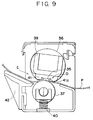
- a fixing system comprising a fixedly supported flat plate-shaped ceramic heater 35, a heat-resisting film 36 shiftable while contacting with the heater 35, and a pressure roller 37 for urging a transfer sheet P against the heater 35 via the film 36 (refer to Japanese Patent Laid-open No. 63-313182). More specifically, as shown in Fig. 9, the heat-resisting film 36 is held for rotation around a guide member 39.
- the elastic pressure roller 37 is disposed in confronting relation to the ceramic heater 35 and is urged against the heater with the interposition of the film 36 therebetween by means of a compression spring 40.
- the film is slightly tensioned by means of a projection 41a integrally formed on a heater holder 41 in the proximity of the heater 35 at an upstream side thereof, so that the wrinkles and/or irregularity in the film are removed to form a stable flat nip portion as indicated by D.
- a pressure at a central portion B in the nip is slightly greater than those at upstream and donwstream portions A, C, the transfer sheet P is curved to form a downwardly directed concave portion.
- the transfer sheet with the downwardly directed concave portion (generated at the nip portion) is heated by the heater 35 and then is subjected to the natural cooling, a great downwardly directed concave curl is generated in the transfer sheet, as shown by the portion D in Fig. 9.
- the transfer sheet P with the downwardly directed concave portion (generated at the fixing nip portion D) is forcibly curved upwardly by providing a sheet discharge guide 42 extending leftwardly and upwardly from the downstream side of the pressure roller 37, as shown by a portion E in Fig. 9. Then, by cooling the transfer sheet P naturally, the curl in the sheet is surpressed.
- the transfer sheet P that the curl is corrected as mentioned above is suited for an electrophotographic system having a sheet discharging apparatus for discharging a sheet in a face-up manner.
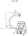
- a problem that the sheet is again curled upwardly at an inverting portion 43 (portion F) (refer to Fig. 11).
- a radius of curvature of the inverting portion 43 shown in Fig. 10 may be increased, or the transfer sheet P may be forcibly cooled by using a fan and the like, or a distance between the fixing device and the inverting portion 43 may be increased so as to permit the adequate cooling of the sheet.
- these techniques will make the compactness and cost-down of the laser beam printer and the like difficult.
- the present invention aims to eliminate the above-mentioned conventional drawbacks, and an object of the present invention is to provide a sheet discharging apparatus having a curl correcting means which can discharge or eject a sheet with less curl.
- a sheet discharging apparatus having a curl correcting means wherein a sheet discharge guide driven in synchronous with a guide member to correct the curl generated in a sheet at a curl generating means is disposed between the curl generating means and the guide member.
- a sheet discharging apparatus comprises a fixing device (curl generating means) for fixing an image transferred to a transfer sheet onto the latter with heat and pressure, and a guide member disposed at a downstream side of the fixing device and pivotable between a first position where the transfer sheet is guided toward a discharging direction of the fixing device and a second position where the transfer sheet is guided to be inverted from the discharging direction of the fixing device, and further comprises a sheet discharge guide diposed between the fixing device and the guide member and driven in synchronous with the guide member to correct the curl generated in the transfer sheet at the fixing device.
- the fixing device and the sheet discharge guide are constructed and arranged so that a downwardly directed curl is generated in the transfer sheet by the fixing device and an upwardly directed curl is generated in the transfer sheet by the sheet discharge guide driven in synchronous with the guide member positioned in the first position without generating the curl in the transfer sheet by the sheet discharge guide driven synchronous with the guide member positioned in the second position.
- the transfer sheet is discharged toward the discharging direction of the fixing device at the first position of the guide member, and then the transfer sheet is inverted from the discharging direction of the fixing device at the second position of the guide member, thus ejecting the sheet.
- the curl generated in the transfer sheet at the fixing device is corrected, thereby permitting the discharge of the transfer sheet with less curl.
- the donwwardly directed curl is geneated in the transfer sheet by the fixing device and the upwardly directed curl is generated in the transfer sheet by the sheet discharge guide driven in synchronous with the guide member positioned in the first position; but the curl is not generated in the transfer sheet by the sheet discharge guide driven synchronous with the guide member positioned in the second position.
- the sheet discharge guide driven in synchronous with the guide member to correct the curl generated in the transfer sheet at the curl generating means is disposed between the guide member and the curl generating means, it is possible to minimize the curl in the sheet on which the image was formed and which is to be discharged, with a simple construction.
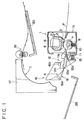
- a fixing device 1 has a body frame 1a within which a ceramic heater 2 acting as a heat source is supported by a fixed support member 5 via a holder 3.
- a heat-resisting fixing film 6 is disposed around the support member 5 for rotation therearound.
- An elastic pressure roller 7 is urged against the heater 2 with the interposition of the film 6 therebetween, by means of a pressure spring 10 via a spring receiver 9.
- a separating guide 11 having a horizontal upper surface 11a is secured to the body frame 1a and serves to prevent a sheet P from wrapping around the pressure roller 7.
- a sheet discharge guide 12 is pivotally mounted on the separating guide 11 via pins 12a formed on both ends of the sheet discharge guide, so that a guide surface 12a of the sheet discharge guide is contiguous to the upper surface 11a of the separating guide 11.
- ribs 12c formed on both lateral edges of the upper surface of the sheet discharge guide are locked against fixed stoppers 13 to limit the upward rocking movement of the sheet discharge guide 12.
- a compression spring 15 disposed between a lower portion of the sheet discharge guide 12 and the separating guide 11 serves to bias the sheet discharge guide 12 in a clockwise direction.
- a flapper 16 is rotatably supported on a pivot shaft 16a at a downstream side of the sheet discharge guide 12.
- the flapper has an upwardly directed concave upper surface A and a substantially flat lower surface B.
- stoppers 16b are secured to ribs formed on both lateral edges of the flapper, which stoppers can be engaged by the ribs 12c formed on the sheet discharge guide 12.
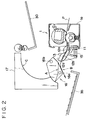
- a rib 17 formed on a wall of a sheet discharging portion defines an inwardly directed concave sheet discharge path C at its free end, and a sheet discharge roller 19 is disposed in the vicinity of the exit of the sheet discharge path C.
- a downstream end of the upper surface 11a of the separating guide 11 is slightly higher than an upstream end of the guide surface 12b and a downstream end of the guide surface 12b is slightly higher than an upstream end of the surface A and a downstream end of the surface A is slightly inner more than an upstream end of the sheet discharge path C, so that the sheet P being fed is not caught by these elements.
- Fig. 3 is a plan view showing the arrangement of these elements.
- a downwardly directed curl generated in the sheet P at a fixing nip portion between the fixing roller and the pressure roller is not corrected by the guide surface 12b of the sheet discharge guide 12; but, this curl is cancelled by an upwardly directed curl generated in the sheet at the sheet discharge path C, with the result that the curl remaining in the sheet P discharged onto a tray 30 via the sheet discharge roller 19 will become smaller. Therefore, according to this embodiment, it is possible to omit a curl removing roller which was required in association with the sheet discharge roller in the conventional sheet discharging apparatus.
- the guide surface 12b of the sheet discharge guide 12 is inclined leftwardly and upwardly by about 40 degrees, the downwardly directed curl generated in the sheet P at the fixing nip portion is substantially cancelled by an upwardly directed curl generated in the sheet at the guide surface 12b. Then, the sheet P is passed below the lower surface B of the flapper 16 and is discharged on a sheet discharge tray 35, with less curl (Fig. 2).
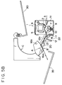
- a hooked arm 20 extending downwardly is formed on the lower surface B of the flapper 16, and a recess 21 for receiving a hooked end of the arm 20 is formed in the lower surface of the sheet discharge guide 12. Further, there is provided a stopper 22 against which the sheet discharge guide 12 is abutted when the latter is substantially in a horizontal position (Fig. 5A) for the face-down sheet discharge.
- toothed segments 23, 25 are formed on the flapper 16 and the sheet discharge guide 12, respectively, which toothed segments 23, 25 are meshed with each other and can be rotated around the pivots 16a, 12a, respectively.
- the gear ratio between the toothed segments is selected so that the same rotations of the flapper and of the sheet discharge guide as those in the first and second embodiments are obtained.
- the present invention may be applied to a fixing device which comprises an upper pressure roller and a lower fixing roller and wherein a downwardly directed curl is generated in the sheet at a fixing nip.
- the flapper 16 and the sheet discharge guide 12 may be interconnected via linkage and the like so that they are rotated in synchronous with each other.
- the fixing device may be of heat fixing type, pressure fixing type or heat/pressure fixing type.
- a sheet discharging apparatus comprising, curl generating means wherein a curl is generated in a sheet while the sheet is passing through the curl generating means, and guide means disposed downstream of the curl generating means and switchingly movable between a first position where the sheet is directed toward a curved sheet path and a second position where the sheet is directed toward a direction same as a sheet feeding direction from the curl generating means.
- Apparatus further comprising sheet discharge guide means disposed between the curl generating means and the guide means and switchingly movable in synchronous with the switching movement of the guide means to change its posture, between a position where the sheet discharged from the curl generating means is curled reversely and a position where the sheet discharged from the curl generating means is not further curled.
Landscapes
- Physics & Mathematics (AREA)
- General Physics & Mathematics (AREA)
- Engineering & Computer Science (AREA)
- Mechanical Engineering (AREA)
- Separation, Sorting, Adjustment, Or Bending Of Sheets To Be Conveyed (AREA)
- Handling Of Continuous Sheets Of Paper (AREA)
- Paper Feeding For Electrophotography (AREA)
- Feeding Of Articles By Means Other Than Belts Or Rollers (AREA)
- Handling Of Cut Paper (AREA)
Applications Claiming Priority (2)
| Application Number | Priority Date | Filing Date | Title |
|---|---|---|---|
| JP22874/91 | 1991-01-23 | ||
| JP3022874A JPH04243765A (ja) | 1991-01-23 | 1991-01-23 | 排紙装置 |
Publications (3)
| Publication Number | Publication Date |
|---|---|
| EP0496375A2 true EP0496375A2 (fr) | 1992-07-29 |
| EP0496375A3 EP0496375A3 (en) | 1992-11-19 |
| EP0496375B1 EP0496375B1 (fr) | 1997-09-10 |
Family
ID=12094843
Family Applications (1)
| Application Number | Title | Priority Date | Filing Date |
|---|---|---|---|
| EP92101002A Expired - Lifetime EP0496375B1 (fr) | 1991-01-23 | 1992-01-22 | Appareil de sortie de feuilles avec moyens de la correction de gondolage |
Country Status (5)
| Country | Link |
|---|---|
| US (1) | US5237381A (fr) |
| EP (1) | EP0496375B1 (fr) |
| JP (1) | JPH04243765A (fr) |
| KR (1) | KR950011869B1 (fr) |
| DE (1) | DE69222070T2 (fr) |
Cited By (3)
| Publication number | Priority date | Publication date | Assignee | Title |
|---|---|---|---|---|
| WO1996028301A1 (fr) * | 1995-03-16 | 1996-09-19 | Minnesota Mining And Manufacturing Company | Appareil et procede eliminant les defauts de laminage |
| EP0860291A3 (fr) * | 1997-02-19 | 1999-01-20 | Alps Electric Co., Ltd. | Imprimante avec un dispositif de redressage du gondolement des feuilles |
| EP1014208A3 (fr) * | 1998-12-21 | 2002-01-02 | Sharp Kabushiki Kaisha | Système de transport de feuilles |
Families Citing this family (30)
| Publication number | Priority date | Publication date | Assignee | Title |
|---|---|---|---|---|
| US5398107A (en) * | 1992-09-30 | 1995-03-14 | T/R Systems, Inc. | Apparatus for biasing the curvature of an image carrier on a transfer drum |
| JP2500414B2 (ja) * | 1992-12-11 | 1996-05-29 | 日本電気株式会社 | 電子写真装置の用紙送り機構 |
| JP3213424B2 (ja) * | 1993-02-15 | 2001-10-02 | 理想科学工業株式会社 | 孔版印刷装置の排紙装置 |
| US5426497A (en) * | 1994-05-18 | 1995-06-20 | Eastman Kodak Company | Roller pair assembly usable in image forming apparatus |
| US5548389A (en) * | 1994-12-19 | 1996-08-20 | Xerox Corporation | Variable position stripper system for curl reduction |
| KR200154398Y1 (ko) * | 1995-07-13 | 1999-08-02 | 윤종용 | 감열기록지 펴짐 장치 |
| JP3450623B2 (ja) * | 1997-01-21 | 2003-09-29 | キヤノン株式会社 | 画像形成装置 |
| JP3411787B2 (ja) * | 1997-06-20 | 2003-06-03 | 株式会社 沖情報システムズ | 媒体処理装置 |
| US6011940A (en) * | 1998-09-25 | 2000-01-04 | Hewlett-Packard Co. | Method and apparatus for convenience copy collation during a current print job |
| US6131902A (en) * | 1998-11-20 | 2000-10-17 | Ricoh Company, Ltd. | Sheet feeding paths for apparatus with feed paths selectable to correspond to desired function of apparatus |
| JP2000352887A (ja) * | 1999-04-08 | 2000-12-19 | Canon Inc | 定着装置および画像形成装置 |
| US6511241B2 (en) | 2001-01-12 | 2003-01-28 | Hewlett-Packard Company | Integral actuation linkage for paper diverter for switch to straight-through paper path |
| JP4745521B2 (ja) * | 2001-03-29 | 2011-08-10 | キヤノン株式会社 | 加熱装置及び画像形成装置 |
| US7128236B2 (en) * | 2002-09-13 | 2006-10-31 | Avery Dennison Corporation | Versatile label sheet and dispenser |
| US6991130B2 (en) * | 2002-09-13 | 2006-01-31 | Avery Dennison Corporation | Versatile label sheet and dispenser |
| US7059181B2 (en) * | 2003-11-10 | 2006-06-13 | International Paper Co. | Test to measure curling tendency of paper in laser printers |
| JP4537226B2 (ja) * | 2005-02-28 | 2010-09-01 | キヤノン株式会社 | 画像形成装置 |
| JP4417940B2 (ja) * | 2006-09-29 | 2010-02-17 | 株式会社沖データ | 画像形成装置 |
| JP4963656B2 (ja) * | 2006-10-23 | 2012-06-27 | キヤノン株式会社 | シート搬送装置及び画像形成装置 |
| JP4548536B2 (ja) * | 2008-03-21 | 2010-09-22 | 富士ゼロックス株式会社 | 画像形成装置及び定着装置 |
| JP5023140B2 (ja) * | 2009-12-11 | 2012-09-12 | シャープ株式会社 | 搬送装置 |
| KR101139311B1 (ko) * | 2010-08-31 | 2012-04-26 | 주식회사 비즈테크원 | 용지 혼입방지장치 |
| EP3758945B1 (fr) * | 2018-02-28 | 2022-04-06 | Canon Production Printing Holding B.V. | Dispositif de déviation pour dévier une feuille transportée |
| JP7119586B2 (ja) * | 2018-05-30 | 2022-08-17 | 富士フイルムビジネスイノベーション株式会社 | 画像形成装置 |
| JP7187354B2 (ja) * | 2019-03-06 | 2022-12-12 | 株式会社Pfu | 画像読取装置 |
| US12269234B2 (en) | 2021-07-07 | 2025-04-08 | Brown Llc | Methods and systems for producing pressware |
| US11945670B2 (en) * | 2021-07-07 | 2024-04-02 | Brown Llc | Methods and systems for producing pressware |
| US11919270B2 (en) | 2021-07-07 | 2024-03-05 | Brown Llc | Methods and systems for producing pressware |
| US11938699B2 (en) | 2021-07-07 | 2024-03-26 | Brown Llc | Methods and systems for producing pressware |
| JP7846451B2 (ja) * | 2022-01-21 | 2026-04-15 | セイコーエプソン株式会社 | 媒体搬送装置、画像読取装置 |
Family Cites Families (16)
| Publication number | Priority date | Publication date | Assignee | Title |
|---|---|---|---|---|
| US4013284A (en) * | 1975-10-14 | 1977-03-22 | Eastern Graphic Products, Inc. | Decurler device |
| US4326915A (en) * | 1979-11-15 | 1982-04-27 | Xerox Corporation | Sheet de-curler |
| US4571054A (en) * | 1983-06-01 | 1986-02-18 | Xerox Corporation | Post-fuser copy sheet decurler |
| GB8315732D0 (en) * | 1983-06-08 | 1983-07-13 | Xerox Corp | Sheet curl control apparatus |
| JPS6050547A (ja) * | 1983-08-30 | 1985-03-20 | Mita Ind Co Ltd | 複写機の複写紙案内機構 |
| US4652110A (en) * | 1984-02-29 | 1987-03-24 | Canon Kabushiki Kaisha | Image recording apparatus |
| US4632533A (en) * | 1985-04-01 | 1986-12-30 | Xerox Corporation | Off-set nip roll decurler |
| JPS6175369A (ja) * | 1985-08-30 | 1986-04-17 | Mita Ind Co Ltd | 複写機の複写紙搬送装置 |
| US4639405A (en) * | 1985-09-30 | 1987-01-27 | Eastman Kodak Company | Method and apparatus for fixing toner images |
| JPS6286369U (fr) * | 1985-11-19 | 1987-06-02 | ||
| US4926358A (en) * | 1987-05-20 | 1990-05-15 | Ricoh Company, Ltd. | System for controlling curls of a paper |
| US5066984A (en) * | 1987-11-17 | 1991-11-19 | Gradco Systems, Inc. | Decurler |
| JPH01308357A (ja) * | 1988-06-01 | 1989-12-13 | Minolta Camera Co Ltd | 作像装置 |
| DE68920781T2 (de) * | 1988-06-17 | 1995-06-14 | Canon Kk | Bildaufzeichnungsgerät. |
| US5262834A (en) * | 1988-12-06 | 1993-11-16 | Canon Kabushiki Kaisha | Image fixing apparatus |
| US5084731A (en) * | 1990-12-24 | 1992-01-28 | Eastman Kodak Company | Sheet decurling mechanism and method |
-
1991
- 1991-01-23 JP JP3022874A patent/JPH04243765A/ja active Pending
-
1992
- 1992-01-22 DE DE69222070T patent/DE69222070T2/de not_active Expired - Fee Related
- 1992-01-22 EP EP92101002A patent/EP0496375B1/fr not_active Expired - Lifetime
- 1992-01-22 US US07/823,462 patent/US5237381A/en not_active Expired - Fee Related
- 1992-01-23 KR KR1019920000915A patent/KR950011869B1/ko not_active Expired - Fee Related
Cited By (5)
| Publication number | Priority date | Publication date | Assignee | Title |
|---|---|---|---|---|
| WO1996028301A1 (fr) * | 1995-03-16 | 1996-09-19 | Minnesota Mining And Manufacturing Company | Appareil et procede eliminant les defauts de laminage |
| US5641374A (en) * | 1995-03-16 | 1997-06-24 | Minnesota Mining And Manufacturing Company | Apparatus and method for preventing defects during the lamination of materials |
| EP0860291A3 (fr) * | 1997-02-19 | 1999-01-20 | Alps Electric Co., Ltd. | Imprimante avec un dispositif de redressage du gondolement des feuilles |
| US6000866A (en) * | 1997-02-19 | 1999-12-14 | Alps Electric Co., Ltd. | Printer with sheet curl straightening device |
| EP1014208A3 (fr) * | 1998-12-21 | 2002-01-02 | Sharp Kabushiki Kaisha | Système de transport de feuilles |
Also Published As
| Publication number | Publication date |
|---|---|
| JPH04243765A (ja) | 1992-08-31 |
| US5237381A (en) | 1993-08-17 |
| EP0496375B1 (fr) | 1997-09-10 |
| DE69222070D1 (de) | 1997-10-16 |
| KR920015168A (ko) | 1992-08-26 |
| DE69222070T2 (de) | 1998-02-19 |
| KR950011869B1 (ko) | 1995-10-11 |
| EP0496375A3 (en) | 1992-11-19 |
Similar Documents
| Publication | Publication Date | Title |
|---|---|---|
| US5237381A (en) | Sheet discharging apparatus with curl correcting means | |
| US7426353B1 (en) | Image forming apparatus with variable convey speed control between transfer device and fixing device | |
| JPH06191686A (ja) | 給紙装置 | |
| US8083231B2 (en) | Sheet conveying apparatus and image forming apparatus with opening conveying path | |
| JPH0818740B2 (ja) | シ−ト排出装置 | |
| JPH10177314A (ja) | 定着装置 | |
| JPH063900A (ja) | 画像形成装置 | |
| US7920819B2 (en) | Image forming apparatus with shiftable guide member for preventing curling of a transfer medium | |
| JP2009214975A (ja) | カール矯正装置,画像形成装置および複写機ならびにプリンタ | |
| US9268288B2 (en) | Image forming apparatus with rotatable curling correction portion | |
| US11614702B2 (en) | Fixing device | |
| JPS6327372A (ja) | 画像形成装置 | |
| US6371479B1 (en) | Switchback device for use in image forming apparatus | |
| JP3413148B2 (ja) | シート搬送装置及び画像形成装置 | |
| US6112048A (en) | Apparatus for curling materials | |
| JP6878506B2 (ja) | シート搬送装置及び画像形成装置 | |
| JP3347656B2 (ja) | シート搬送装置 | |
| JP2001022205A (ja) | 定着装置 | |
| JPH07281548A (ja) | 定着装置 | |
| JP2002012355A (ja) | シート搬送装置及び画像形成装置 | |
| US11353811B2 (en) | Fixing device and image forming apparatus | |
| JP3622826B2 (ja) | 排紙装置 | |
| JP3372323B2 (ja) | 用紙搬送装置 | |
| JPH1165360A (ja) | 画像形成装置 | |
| JP2010037087A (ja) | シート搬送装置及びそれを備えた画像形成装置 |
Legal Events
| Date | Code | Title | Description |
|---|---|---|---|
| PUAI | Public reference made under article 153(3) epc to a published international application that has entered the european phase |
Free format text: ORIGINAL CODE: 0009012 |
|
| AK | Designated contracting states |
Kind code of ref document: A2 Designated state(s): DE FR GB IT |
|
| PUAL | Search report despatched |
Free format text: ORIGINAL CODE: 0009013 |
|
| AK | Designated contracting states |
Kind code of ref document: A3 Designated state(s): DE FR GB IT |
|
| 17P | Request for examination filed |
Effective date: 19930405 |
|
| 17Q | First examination report despatched |
Effective date: 19941025 |
|
| GRAG | Despatch of communication of intention to grant |
Free format text: ORIGINAL CODE: EPIDOS AGRA |
|
| GRAH | Despatch of communication of intention to grant a patent |
Free format text: ORIGINAL CODE: EPIDOS IGRA |
|
| GRAH | Despatch of communication of intention to grant a patent |
Free format text: ORIGINAL CODE: EPIDOS IGRA |
|
| GRAA | (expected) grant |
Free format text: ORIGINAL CODE: 0009210 |
|
| AK | Designated contracting states |
Kind code of ref document: B1 Designated state(s): DE FR GB IT |
|
| PG25 | Lapsed in a contracting state [announced via postgrant information from national office to epo] |
Ref country code: IT Free format text: LAPSE BECAUSE OF FAILURE TO SUBMIT A TRANSLATION OF THE DESCRIPTION OR TO PAY THE FEE WITHIN THE PRESCRIBED TIME-LIMIT;WARNING: LAPSES OF ITALIAN PATENTS WITH EFFECTIVE DATE BEFORE 2007 MAY HAVE OCCURRED AT ANY TIME BEFORE 2007. THE CORRECT EFFECTIVE DATE MAY BE DIFFERENT FROM THE ONE RECORDED. Effective date: 19970910 |
|
| REF | Corresponds to: |
Ref document number: 69222070 Country of ref document: DE Date of ref document: 19971016 |
|
| ET | Fr: translation filed | ||
| PLBE | No opposition filed within time limit |
Free format text: ORIGINAL CODE: 0009261 |
|
| STAA | Information on the status of an ep patent application or granted ep patent |
Free format text: STATUS: NO OPPOSITION FILED WITHIN TIME LIMIT |
|
| 26N | No opposition filed | ||
| REG | Reference to a national code |
Ref country code: GB Ref legal event code: IF02 |
|
| PGFP | Annual fee paid to national office [announced via postgrant information from national office to epo] |
Ref country code: FR Payment date: 20040108 Year of fee payment: 13 |
|
| PGFP | Annual fee paid to national office [announced via postgrant information from national office to epo] |
Ref country code: GB Payment date: 20040121 Year of fee payment: 13 |
|
| PGFP | Annual fee paid to national office [announced via postgrant information from national office to epo] |
Ref country code: DE Payment date: 20040129 Year of fee payment: 13 |
|
| PG25 | Lapsed in a contracting state [announced via postgrant information from national office to epo] |
Ref country code: GB Free format text: LAPSE BECAUSE OF NON-PAYMENT OF DUE FEES Effective date: 20050122 |
|
| PG25 | Lapsed in a contracting state [announced via postgrant information from national office to epo] |
Ref country code: DE Free format text: LAPSE BECAUSE OF NON-PAYMENT OF DUE FEES Effective date: 20050802 |
|
| GBPC | Gb: european patent ceased through non-payment of renewal fee |
Effective date: 20050122 |
|
| PG25 | Lapsed in a contracting state [announced via postgrant information from national office to epo] |
Ref country code: FR Free format text: LAPSE BECAUSE OF NON-PAYMENT OF DUE FEES Effective date: 20050930 |
|
| REG | Reference to a national code |
Ref country code: FR Ref legal event code: ST |