EP0496643A1 - Thermischer Schalter/Ausschalter - Google Patents
Thermischer Schalter/Ausschalter Download PDFInfo
- Publication number
- EP0496643A1 EP0496643A1 EP92300656A EP92300656A EP0496643A1 EP 0496643 A1 EP0496643 A1 EP 0496643A1 EP 92300656 A EP92300656 A EP 92300656A EP 92300656 A EP92300656 A EP 92300656A EP 0496643 A1 EP0496643 A1 EP 0496643A1
- Authority
- EP
- European Patent Office
- Prior art keywords
- actuator
- flag
- tooth
- rocker
- trip
- Prior art date
- Legal status (The legal status is an assumption and is not a legal conclusion. Google has not performed a legal analysis and makes no representation as to the accuracy of the status listed.)
- Granted
Links
Images

Classifications
-
- H—ELECTRICITY
- H01—ELECTRIC ELEMENTS
- H01H—ELECTRIC SWITCHES; RELAYS; SELECTORS; EMERGENCY PROTECTIVE DEVICES
- H01H73/00—Protective overload circuit-breaking switches in which excess current opens the contacts by automatic release of mechanical energy stored by previous operation of a hand reset mechanism
- H01H73/22—Protective overload circuit-breaking switches in which excess current opens the contacts by automatic release of mechanical energy stored by previous operation of a hand reset mechanism having electrothermal release and no other automatic release
- H01H73/26—Protective overload circuit-breaking switches in which excess current opens the contacts by automatic release of mechanical energy stored by previous operation of a hand reset mechanism having electrothermal release and no other automatic release reset by tumbler
-
- H—ELECTRICITY
- H01—ELECTRIC ELEMENTS
- H01H—ELECTRIC SWITCHES; RELAYS; SELECTORS; EMERGENCY PROTECTIVE DEVICES
- H01H73/00—Protective overload circuit-breaking switches in which excess current opens the contacts by automatic release of mechanical energy stored by previous operation of a hand reset mechanism
- H01H73/22—Protective overload circuit-breaking switches in which excess current opens the contacts by automatic release of mechanical energy stored by previous operation of a hand reset mechanism having electrothermal release and no other automatic release
- H01H73/30—Protective overload circuit-breaking switches in which excess current opens the contacts by automatic release of mechanical energy stored by previous operation of a hand reset mechanism having electrothermal release and no other automatic release reset by push-button, pull-knob or slide
- H01H73/303—Protective overload circuit-breaking switches in which excess current opens the contacts by automatic release of mechanical energy stored by previous operation of a hand reset mechanism having electrothermal release and no other automatic release reset by push-button, pull-knob or slide with an insulating body insertable between the contacts when released by a bimetal element
Definitions
- This invention relates generally to a thermal switch/breaker having as one function electrical on/off switching capability, and also including a built in circuit overload protection function. More particularly, this invention relates to an electric switch of conventional rocker appearance having at least one contact provided on a temperature responsive bimetallic element. When the bimetallic element is subjected to electrical resistance heating the switch contacts open, the rocker returns to its OFF condition, and an insulating flag moves between the contacts. The contacts cannot be recycled even if the rocker is held in its ON condition thereby providing "trip free" operation.
- Getchell, Patent No. 1,708,222 illustrates a thermally responsive bimetallic element carrying a contact which is engaged by an insulating flag when the switch is toggled to the off condition, and which flag is adapted to be automatically switched to the off condition in response to heating of the bimetallic element.
- a spring is provided for moving the insulating flag from the ON condition of the contacts to the OFF condition.
- Patent No. 4,833,439 illustrates a combination switch and circuit protection device incorporating a bimetallic element carrying a moveable contact wherein a flag is adapted to move between the contacts in the switch closed position and to be moved out of this position when the contacts are opened.
- the device is not capable of "trip free” operation in that the moveable actuator can be held in its ON position with the result that the thermally responsive contact will be physically closed unless and until the bimetallic element is again reheated.
- the general purpose of the present invention is to provide a combination switch and circuit breaker device that exhibits "trip free” operation, and which comprises fewer moving parts than these prior art patents.
- Butler, Patent No. 3,311,725 like the device of the present invention provides for pivotable movement of the actuator
- the present disclosure provides a switch configuration that is more like a conventional rocker switch than is the push button circuit breaker type device of Getchell or the toggle device of Butler.
- the thermal switch is also configured to receive an indicator light behind the rocker for a visual indication of the electrical condition of the device itself (ie: ON or OFF).
- an electrical switch/breaker is provided in a generally rectangular housing having an upwardly open cavity for receiving a pivotable actuator or rocker.
- a moveable contact is provided within the housing on a bimetallic temperature responsive spring element having a free end portion defining a movable contact.
- the inherent resiliency of the spring element normally holds the moveable contact against a fixed contact in the housing and the bimetallic element biases the movable contact away from the fixed contact by the inherent temperature responsive characteristics of the bimetallic spring element.
- a trip flag is moveably supported in the housing so that one portion of the flag is adapted to rest against the moveable contact when the contacts are closed, and this one flag portion is adapted to move between the moveable and fixed contacts when the switch is open.
- the trip flag has a cam lobe or tooth defined adjacent an opposite end portion and this trip flag tooth is engageable by a first cam surface on the pivoting rocker/actuator to create compound movement of the trip flag from a rest position (where the flag rests against the moveable contact) to a cocked position wherein the flag is spaced from the moveable contact and the fixed contact.
- a rest position where the flag rests against the moveable contact
- a cocked position wherein the flag is spaced from the moveable contact and the fixed contact.
- Biasing means urges the trip flag tooth into contact with the actuators first cam surface, and also urges the one flag portion thereof toward its active position between the fixed and moveable contacts.
- the biasing means provides a snap action of the trip flag from the above-mentioned cocked position to the active position.
- the biasing means also holds the rocker/actuator in the ON position by the interaction between the cam surface on the rocker and cam lobe or tooth on the trip flag.
- the actuator or rocker also includes a second cam surface, and coupling means is provided between the second cam surface and the bimetallic spring element for moving the moveable contact away from the fixed contact as the actuator/rocker is moved from ON to OFF.
- Fig. 1 is a vertical section taken through a switch/breaker constructed in accordance with the present invention, and illustrates the rocker/actuator in position for closing the contacts.
- the phantom lines show the rocker/actuator in positioned for opening the contacts.
- a trip flag is driven by the rocker and is also shown in phantom lines in an active position between the moveable and fixed contacts. The solid line position shows the trip flag in its rest position.
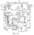
- Fig. 1A illustrates the switch of Fig. 1 with the rocker/actuator in an intermediate position and also illustrates the trip flag in a cocked position.
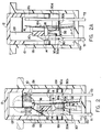
- Fig. 2 is a vertical section taken generally on the line 2-2 of Fig. 1.
- Fig. 2A is a sectional view of the switch/breaker showing the rocker in the off position with the trip flag in its active position between the movable and fixed contacts.
- Fig. 3 is a generally horizontal section taken on the line 3-3 of Fig. 1, and illustrates a coupling wedge in two positions, that is in the phantom line position for opening the switch contacts and in the solid line position for closing the switch contacts.
- Fig. 1 shows a switch/breaker constructed in accordance with the present invention.
- the housing 10 is upwardly open and has a top flange so it can be conveniently mounted in a panel opening or the like.
- the housing 10 has a pivotable rocker 12 provided in the open top, and the rocker is moveable between the solid and phantom line positions shown on a pivot axis 12a defined in the switch housing.
- the rocker 12 may include laterally projecting axle portions (not shown) that are in turn received in openings provided for this purpose in the side walls of the housing.
- the switch housing 10 has a bottom wall 10c defining openings for at least two terminals T1 and T2 as best shown in Fig. 2.
- the terminal T1 is electrically connected to a fixed contact 14 inside the switch housing.
- the fixed contact 14 is preferably mounted on an extension of the terminal T1 as best shown in Fig. 2.
- the second terminal T2 also has a portion extending inside the switch housing cavity and is electrically connected, as for example by riveting or the like, to one end portion of a bimetallic temperature responsive element 16.
- the bimetallic element 16 has a U-shaped slot 16a defined therein with the result that a tongue portion 16b is adapted to deform in response to a predetermined temperature rise of the bimetallic material from which it is made.
- This element 16, and its tongue portion 16b move between the positions illustrated in Fig. 2 and Fig. 2A.
- a moveable contact element 18 is provided on the spring element arm 16b.
- the bimetallic element 16 with its associated moveable arm portion 16b is of conventional geometry.
- Element 16 is sometimes referred to as a "Taylor" blade and is available from Demich Industries, 70 Mill Street, Johnston, RI 02919.
- the bimetallic element 16 is adapted to move from the normal contacts closed position of Fig. 2 toward the position illustrated in Fig. 2A as a result of thermal expansion of the bimetallic element 16 caused by an overcurrent condition in a circuit (not shown) defined between the load and line terminals T1 and T2 in these views.
- the cantilever mounted bimetallic element 16 has its root end secured by a rivet or the like to the fixed terminal T2 as indicated generally at 17.
- the free end portion of the element 16 is adapted to move from the position shown in Fig. 2 to that shown in Fig. 2A.
- the depending spring element arm portion 16b will also move from the position shown for it in Fig. 2 to that illustrated in Fig. 2A and the result is to achieve opening movement of movable contact 18 relative to the fixed contact 14.
- thermal expansion of the bimetallic element 16 corresponds to opening movement of the contact 18.
- mechanical opening movement of the contact 18 is also possible through movement of the rocker 12 from the contacts closed position shown in solid lines in Fig. 1 to the phantom line position illustrated in that view.
- the rocker 12 has a tapered cam surface 12f on an integrally formed leg. This cam moves from the position shown for it in Fig. 2 to the position shown in Fig. 1 during movement of the rocker 12 from the solid line position in Fig. 1 to the phantom line position in that view.
- Fig. 3 is a horizontal section taken generally on the line 3-3 of Fig. 2A.
- the cam surface 12f on rocker 12 is adapted to move downwardly and to move the wedge 20 between the solid and phantom line positions illustrated in Fig. 3.
- the pivoted wedge or coupling element 20 has one end portion 20a pivotably received in a socket defined for this purpose in the end wall of the housing 10 as best shown in Fig. 3. Downward movement of the actuator cam surface 12f causes horizontal pivoting movement of the wedge or coupling means 20 from the solid to the phantom line position illustrated in Fig. 3.
- the cantilever mounted bimetallic element 16, and more particularly the depending arm portion 16b, is moved by the coupling element or wedge 20 from the solid line position illustrated in Fig. 3 to the phantom line position illustrated in this view.
- Fig. 2 and Fig. 2A show such movement of the coupling means 20 and of the bimetallic element arm 16b. It will be apparent that the above-mentioned cam surface 12f on the actuator 12 causes mechanical opening of the contact 18 as a result of rocker movement between the solid line and the phantom line position illustrated in Fig. 1.
- each depending cam lobe or tooth 12d is adapted to engage a cam lobe or tooth on a moveable trip flag to be described.
- each depending cam lobe or tooth 12d on the rocker 12 moves between the limit positions shown in Fig. 1 in solid and phantom lines.
- the tooth 12d cooperates with one face or side of an upstanding cam lobe or tooth 30d on one end of the trip flag 30, and for reasons to be described defines a rest position for the trip flag 30 such that an opposite end portion 30a of the trip flag 30 rests against the moveable contact 18 as best shown in Fig. 2.
- Fig. 1 In the phantom line position shown for the rocker 12 in Fig. 1 the cam lobe or tooth 12d on the rocker cooperates with the opposite side or face of the upstanding cam lobe or tooth 30d of the trip flag 30 to define a position for the trip flag 30 such that the opposite or free end portion 30a has moved upwardly between the fixed and moveable contacts to the active position such as that illustrated in phantom lines in Fig. 1.
- Fig 2A shows the flag 30 in its active position between the contact 14 and 18. In this active position the trip flag 30 provides an effective electrical insulation between these fixed and moveable contacts 14 and 18.
- the trip flag 30 has two end portions 30d which cooperate with the two teeth 12d laterally spaced on the depending skirt portions 12c of the rocker 12. Still with reference to the trip flag 30 it will be apparent from Fig. 2 and Fig. 2A that the trip flag 30 defines at least one and preferably two axle portions 30b, which are in turn received in vertically elongated slots 10d as best shown in Fig. 1 and Fig. 1A.
- Fig. 1A illustrates in solid line the position for the rocker 12 and the trip flag 30 when the trip flag 30 is in its cocked position, that is in a transitory (unstable) position during movement of the trip flag 30 from the solid to the phantom line position of Fig. 1.
- this cocked position it will be apparent that the end portion 30a of the trip flag 30 has moved away from the contacts 14 and 18 so as to compress the return spring 32 and create a snap-action of the trip flag 30 during contact opening movement of the movable switch/breaker components.
- the switch/breaker of the present invention is "trip free" in operation in that once element 16 has caused the rocker to move to its OFF position, manually moving the rocker back to ON will prevent the components of the device from resuming their ON positions until the element 16 has returned to its normal temperature.
- the switch/breaker may have a lamp L provided inside the rocker 12, and more specifically between the rocker skirts 12c,12c.
- lamp leads electrically connect the lamp to at least one terminal T 1 , and to a third terminal T3.
- a resistor R is provided in a cavity defined for this purpose inside the housing, and a spring 40 serves to connect the lamp through the resistor to the terminal T3.
- a second spring 42 connects the lamp to the terminal T 1 .
- the spring 32 urges the rocker toward it's ON position as a result of the geometry of the trip flag tooth 30d and that of the cam lobe tooth 12d of the rocker.
- the spring 32 acts through the flag to hold these teeth in engagement with one another.
- spring 32 serves several purposes, it provides a stable ON position for the rocker 12, it provides a snap action for the flag to move between the contacts when the contacts are open, and yet it exerts a light force on the movable contact itself when the contacts are closed and the rocker is ON.
- the trip flag abuts the movable contact only at the end 30a, so spring 32 exerts only a light force at that location, most of the force from the spring in the ON position (Fig. 1) being reacted by the interengaging teeth 12d and 30d as described previously.
Landscapes
- Thermally Actuated Switches (AREA)
- Cookers (AREA)
- Electric Stoves And Ranges (AREA)
- Electronic Switches (AREA)
- Breakers (AREA)
Applications Claiming Priority (2)
| Application Number | Priority Date | Filing Date | Title |
|---|---|---|---|
| US646156 | 1991-01-25 | ||
| US07/646,156 US5089799A (en) | 1991-01-25 | 1991-01-25 | Thermal switch/breaker |
Publications (2)
| Publication Number | Publication Date |
|---|---|
| EP0496643A1 true EP0496643A1 (de) | 1992-07-29 |
| EP0496643B1 EP0496643B1 (de) | 1995-04-12 |
Family
ID=24591992
Family Applications (1)
| Application Number | Title | Priority Date | Filing Date |
|---|---|---|---|
| EP92300656A Expired - Lifetime EP0496643B1 (de) | 1991-01-25 | 1992-01-27 | Thermischer Schalter/Ausschalter |
Country Status (5)
| Country | Link |
|---|---|
| US (1) | US5089799A (de) |
| EP (1) | EP0496643B1 (de) |
| JP (1) | JPH0668774A (de) |
| AT (1) | ATE121218T1 (de) |
| DE (1) | DE69201970T2 (de) |
Cited By (3)
| Publication number | Priority date | Publication date | Assignee | Title |
|---|---|---|---|---|
| EP1265262A1 (de) * | 2001-06-07 | 2002-12-11 | SIGNAL LUX MDS S.r.l. | Schalter mit thermischem Lastschalter |
| US6617951B2 (en) * | 2001-08-24 | 2003-09-09 | Tsung-Mou Yu | Safety switch |
| GB2404285A (en) * | 2003-07-08 | 2005-01-26 | Otter Controls Ltd | A thermally responsive control for a liquid heating vesel |
Families Citing this family (24)
| Publication number | Priority date | Publication date | Assignee | Title |
|---|---|---|---|---|
| US5264817A (en) * | 1993-02-11 | 1993-11-23 | Sorenson Richard W | Thermal circuit protective device |
| US5982269A (en) * | 1996-06-14 | 1999-11-09 | Sorenson; Richard W. | Electric switch and thermal protector |
| US5828287A (en) * | 1996-12-31 | 1998-10-27 | Nilson; Bruce G. | Automatic thermal shut-off switch |
| US6057751A (en) * | 1999-02-01 | 2000-05-02 | Hung; Kuang-Tsan | Overheat and overload sensing device |
| US6094126A (en) * | 1999-06-08 | 2000-07-25 | Sorenson; Richard W. | Thermal circuit breaker switch |
| AU765338B2 (en) * | 1999-07-22 | 2003-09-18 | Klaus Bruchmann | Fuse combination unit and operating rocker with monitoring display |
| US6252490B1 (en) * | 1999-10-21 | 2001-06-26 | Wen-Jang Lin | Safety plug and switch device |
| US6542061B2 (en) * | 2001-04-16 | 2003-04-01 | Cathy D. Santa Cruz | Indicator light for use in combination with an electrical circuit protector or fuse |
| US6570480B1 (en) * | 2002-01-02 | 2003-05-27 | Albert Huang | Circuit breaker |
| US6714116B1 (en) | 2002-01-22 | 2004-03-30 | Rototech Electrical Components, Inc. | Circuit breaker switch |
| TWM254716U (en) * | 2003-12-25 | 2005-01-01 | Wan-Guo Guo | Improved structure of circuit breaker |
| US7248140B2 (en) * | 2005-03-05 | 2007-07-24 | Tsung-Mou Yu | Adjustable safety switch |
| PL1859466T3 (pl) * | 2005-03-12 | 2012-03-30 | Ellenberger & Poensgen | Wyłącznik ochronny dla zabezpieczenia obwodu prądowego |
| US7317375B2 (en) * | 2005-03-29 | 2008-01-08 | Tsung-Mou Yu | Adjustable safety switch |
| US7283031B2 (en) * | 2005-06-07 | 2007-10-16 | Albert Huang | Circuit breaker |
| US7307506B2 (en) * | 2005-07-22 | 2007-12-11 | Tsung Mou Yu | Safety switches |
| US7304560B2 (en) * | 2005-08-12 | 2007-12-04 | Tsung Mou Yu | Safety switches |
| US20080074231A1 (en) * | 2006-09-22 | 2008-03-27 | Albert Huang | Safety switch |
| US7589610B2 (en) * | 2007-09-21 | 2009-09-15 | Albert Huang | Over current cut-off switch |
| US7688174B2 (en) * | 2008-08-12 | 2010-03-30 | Zing Ear Enterprise Co., Ltd. | Overload protection switch |
| US7948351B2 (en) * | 2009-04-09 | 2011-05-24 | Tsung Mou Yu | Circuit protection device having warning function |
| US20110162947A1 (en) * | 2010-01-07 | 2011-07-07 | Albert Huang | Safety switch |
| US8860313B2 (en) | 2011-11-30 | 2014-10-14 | Lutron Electronics Co., Inc. | Universal-voltage self-heating thermal detector |
| US20150028990A1 (en) * | 2013-07-24 | 2015-01-29 | Albert Huang | Safety switch with over-current protection |
Citations (3)
| Publication number | Priority date | Publication date | Assignee | Title |
|---|---|---|---|---|
| EP0151692A2 (de) * | 1983-11-22 | 1985-08-21 | Ellenberger & Poensgen GmbH | Druckknopfbetätigter Überstromschutzschalter |
| DE3526785C1 (de) * | 1985-07-26 | 1986-07-17 | Ellenberger & Poensgen Gmbh, 8503 Altdorf | Druckknopfbetaetigter UEberstromschutzschalter |
| US4833439A (en) * | 1985-11-27 | 1989-05-23 | Slater Electric, Inc. | Unitary switch and circuit breaker |
Family Cites Families (3)
| Publication number | Priority date | Publication date | Assignee | Title |
|---|---|---|---|---|
| US1708222A (en) * | 1927-05-02 | 1929-04-09 | Trumbull Electric Mfg Co | Electric relay |
| US3311725A (en) * | 1965-10-23 | 1967-03-28 | Mechanical Products Inc | Circuit breaker with lost motion lockout member for interposing between contacts |
| US5004994A (en) * | 1990-05-24 | 1991-04-02 | Cooper Industries, Inc. | Push-to-trip high-amp circuit breaker |
-
1991
- 1991-01-25 US US07/646,156 patent/US5089799A/en not_active Expired - Fee Related
-
1992
- 1992-01-27 JP JP4052020A patent/JPH0668774A/ja active Pending
- 1992-01-27 DE DE69201970T patent/DE69201970T2/de not_active Expired - Fee Related
- 1992-01-27 EP EP92300656A patent/EP0496643B1/de not_active Expired - Lifetime
- 1992-01-27 AT AT92300656T patent/ATE121218T1/de not_active IP Right Cessation
Patent Citations (3)
| Publication number | Priority date | Publication date | Assignee | Title |
|---|---|---|---|---|
| EP0151692A2 (de) * | 1983-11-22 | 1985-08-21 | Ellenberger & Poensgen GmbH | Druckknopfbetätigter Überstromschutzschalter |
| DE3526785C1 (de) * | 1985-07-26 | 1986-07-17 | Ellenberger & Poensgen Gmbh, 8503 Altdorf | Druckknopfbetaetigter UEberstromschutzschalter |
| US4833439A (en) * | 1985-11-27 | 1989-05-23 | Slater Electric, Inc. | Unitary switch and circuit breaker |
Cited By (4)
| Publication number | Priority date | Publication date | Assignee | Title |
|---|---|---|---|---|
| EP1265262A1 (de) * | 2001-06-07 | 2002-12-11 | SIGNAL LUX MDS S.r.l. | Schalter mit thermischem Lastschalter |
| US6617951B2 (en) * | 2001-08-24 | 2003-09-09 | Tsung-Mou Yu | Safety switch |
| GB2404285A (en) * | 2003-07-08 | 2005-01-26 | Otter Controls Ltd | A thermally responsive control for a liquid heating vesel |
| GB2404285B (en) * | 2003-07-08 | 2006-10-11 | Otter Controls Ltd | Improvements relating to thermal control units |
Also Published As
| Publication number | Publication date |
|---|---|
| JPH0668774A (ja) | 1994-03-11 |
| ATE121218T1 (de) | 1995-04-15 |
| DE69201970D1 (de) | 1995-05-18 |
| EP0496643B1 (de) | 1995-04-12 |
| DE69201970T2 (de) | 1995-08-24 |
| US5089799A (en) | 1992-02-18 |
Similar Documents
| Publication | Publication Date | Title |
|---|---|---|
| EP0496643B1 (de) | Thermischer Schalter/Ausschalter | |
| US6154116A (en) | Thermal circuit breaker switch | |
| US5262748A (en) | Fuseless breaking switch | |
| US5264817A (en) | Thermal circuit protective device | |
| JPS5931817B2 (ja) | 遮断器 | |
| US5847638A (en) | Thermal circuit protector and switch | |
| US5982269A (en) | Electric switch and thermal protector | |
| GB2117568A (en) | Immersed element protection | |
| GB2083286A (en) | Automatic circuit-breaker | |
| US3109907A (en) | Tripping mechanism for electric circuit breaker | |
| US4814739A (en) | Combination push/pull electric switch and circuit breaker | |
| EP1059653A2 (de) | Thermischer Lastschalter | |
| US4518943A (en) | Bimetallic circuit breaker with an auxiliary switch | |
| EP0752155B1 (de) | Kontaktanordnung | |
| US5258732A (en) | Overload relay | |
| JPH0668772A (ja) | 保護スイッチ装置 | |
| US2913542A (en) | Two pole circuit breaker | |
| GB2305013A (en) | Thermostatic switch | |
| CA2026365C (en) | Overload relay | |
| US4912441A (en) | Drive mechanism for circuit breaker | |
| US4048607A (en) | Circuit breaker | |
| US3061697A (en) | Thermal and magnetic trip device | |
| US4764746A (en) | Circuit breaker | |
| US5373272A (en) | High current capacity blade for a circuit breaker | |
| GB2240217A (en) | Electrical switches |
Legal Events
| Date | Code | Title | Description |
|---|---|---|---|
| PUAI | Public reference made under article 153(3) epc to a published international application that has entered the european phase |
Free format text: ORIGINAL CODE: 0009012 |
|
| AK | Designated contracting states |
Kind code of ref document: A1 Designated state(s): AT BE CH DE DK ES FR GB GR IT LI LU MC NL PT SE |
|
| 17P | Request for examination filed |
Effective date: 19920810 |
|
| 17Q | First examination report despatched |
Effective date: 19940407 |
|
| GRAA | (expected) grant |
Free format text: ORIGINAL CODE: 0009210 |
|
| AK | Designated contracting states |
Kind code of ref document: B1 Designated state(s): AT BE CH DE DK ES FR GB GR IT LI LU MC NL PT SE |
|
| PG25 | Lapsed in a contracting state [announced via postgrant information from national office to epo] |
Ref country code: IT Free format text: LAPSE BECAUSE OF FAILURE TO SUBMIT A TRANSLATION OF THE DESCRIPTION OR TO PAY THE FEE WITHIN THE PRESCRIBED TIME-LIMIT;WARNING: LAPSES OF ITALIAN PATENTS WITH EFFECTIVE DATE BEFORE 2007 MAY HAVE OCCURRED AT ANY TIME BEFORE 2007. THE CORRECT EFFECTIVE DATE MAY BE DIFFERENT FROM THE ONE RECORDED. Effective date: 19950412 Ref country code: BE Effective date: 19950412 Ref country code: CH Effective date: 19950412 Ref country code: DK Effective date: 19950412 Ref country code: GR Free format text: LAPSE BECAUSE OF FAILURE TO SUBMIT A TRANSLATION OF THE DESCRIPTION OR TO PAY THE FEE WITHIN THE PRESCRIBED TIME-LIMIT Effective date: 19950412 Ref country code: AT Effective date: 19950412 Ref country code: ES Free format text: THE PATENT HAS BEEN ANNULLED BY A DECISION OF A NATIONAL AUTHORITY Effective date: 19950412 Ref country code: LI Effective date: 19950412 Ref country code: NL Free format text: LAPSE BECAUSE OF FAILURE TO SUBMIT A TRANSLATION OF THE DESCRIPTION OR TO PAY THE FEE WITHIN THE PRESCRIBED TIME-LIMIT Effective date: 19950412 Ref country code: MC Free format text: LAPSE BECAUSE OF NON-PAYMENT OF DUE FEES Effective date: 19950412 |
|
| REF | Corresponds to: |
Ref document number: 121218 Country of ref document: AT Date of ref document: 19950415 Kind code of ref document: T |
|
| ET | Fr: translation filed | ||
| REF | Corresponds to: |
Ref document number: 69201970 Country of ref document: DE Date of ref document: 19950518 |
|
| PG25 | Lapsed in a contracting state [announced via postgrant information from national office to epo] |
Ref country code: PT Effective date: 19950712 Ref country code: SE Effective date: 19950712 |
|
| REG | Reference to a national code |
Ref country code: CH Ref legal event code: PL |
|
| NLV1 | Nl: lapsed or annulled due to failure to fulfill the requirements of art. 29p and 29m of the patents act | ||
| PG25 | Lapsed in a contracting state [announced via postgrant information from national office to epo] |
Ref country code: GB Effective date: 19960127 |
|
| PG25 | Lapsed in a contracting state [announced via postgrant information from national office to epo] |
Ref country code: LU Free format text: LAPSE BECAUSE OF NON-PAYMENT OF DUE FEES Effective date: 19960131 |
|
| PLBE | No opposition filed within time limit |
Free format text: ORIGINAL CODE: 0009261 |
|
| 26N | No opposition filed | ||
| GBPC | Gb: european patent ceased through non-payment of renewal fee |
Effective date: 19960127 |
|
| PG25 | Lapsed in a contracting state [announced via postgrant information from national office to epo] |
Ref country code: FR Effective date: 19960930 |
|
| PG25 | Lapsed in a contracting state [announced via postgrant information from national office to epo] |
Ref country code: DE Effective date: 19961001 |
|
| REG | Reference to a national code |
Ref country code: FR Ref legal event code: ST |