EP0497146A1 - Limitateur de flux pour électrovanne - Google Patents
Limitateur de flux pour électrovanne Download PDFInfo
- Publication number
- EP0497146A1 EP0497146A1 EP92100596A EP92100596A EP0497146A1 EP 0497146 A1 EP0497146 A1 EP 0497146A1 EP 92100596 A EP92100596 A EP 92100596A EP 92100596 A EP92100596 A EP 92100596A EP 0497146 A1 EP0497146 A1 EP 0497146A1
- Authority
- EP
- European Patent Office
- Prior art keywords
- fluid
- valve
- annular flange
- flange means
- notches
- Prior art date
- Legal status (The legal status is an assumption and is not a legal conclusion. Google has not performed a legal analysis and makes no representation as to the accuracy of the status listed.)
- Withdrawn
Links
- 239000012530 fluid Substances 0.000 claims abstract description 55
- 238000010276 construction Methods 0.000 claims description 7
- 230000000694 effects Effects 0.000 abstract description 6
- 229910052751 metal Inorganic materials 0.000 abstract description 4
- 239000002184 metal Substances 0.000 abstract description 4
- 239000004033 plastic Substances 0.000 abstract description 2
- 238000005266 casting Methods 0.000 abstract 1
- 238000000465 moulding Methods 0.000 abstract 1
- 239000000463 material Substances 0.000 description 8
- 238000004891 communication Methods 0.000 description 5
- 230000008901 benefit Effects 0.000 description 4
- 238000000034 method Methods 0.000 description 4
- 230000004907 flux Effects 0.000 description 3
- 230000008569 process Effects 0.000 description 3
- 238000004512 die casting Methods 0.000 description 2
- 238000012986 modification Methods 0.000 description 2
- 230000004048 modification Effects 0.000 description 2
- 230000008520 organization Effects 0.000 description 2
- 238000010008 shearing Methods 0.000 description 2
- HCHKCACWOHOZIP-UHFFFAOYSA-N Zinc Chemical compound [Zn] HCHKCACWOHOZIP-UHFFFAOYSA-N 0.000 description 1
- 229910052782 aluminium Inorganic materials 0.000 description 1
- XAGFODPZIPBFFR-UHFFFAOYSA-N aluminium Chemical compound [Al] XAGFODPZIPBFFR-UHFFFAOYSA-N 0.000 description 1
- 230000015556 catabolic process Effects 0.000 description 1
- 238000003486 chemical etching Methods 0.000 description 1
- 238000004140 cleaning Methods 0.000 description 1
- 230000002079 cooperative effect Effects 0.000 description 1
- 230000000875 corresponding effect Effects 0.000 description 1
- 238000005538 encapsulation Methods 0.000 description 1
- 238000002347 injection Methods 0.000 description 1
- 239000007924 injection Substances 0.000 description 1
- 238000003754 machining Methods 0.000 description 1
- 230000014759 maintenance of location Effects 0.000 description 1
- 238000004519 manufacturing process Methods 0.000 description 1
- 239000002991 molded plastic Substances 0.000 description 1
- 238000010137 moulding (plastic) Methods 0.000 description 1
- 230000004044 response Effects 0.000 description 1
- 229920006395 saturated elastomer Polymers 0.000 description 1
- 238000007789 sealing Methods 0.000 description 1
- 229910052725 zinc Inorganic materials 0.000 description 1
- 239000011701 zinc Substances 0.000 description 1
Images

Classifications
-
- F—MECHANICAL ENGINEERING; LIGHTING; HEATING; WEAPONS; BLASTING
- F16—ENGINEERING ELEMENTS AND UNITS; GENERAL MEASURES FOR PRODUCING AND MAINTAINING EFFECTIVE FUNCTIONING OF MACHINES OR INSTALLATIONS; THERMAL INSULATION IN GENERAL
- F16L—PIPES; JOINTS OR FITTINGS FOR PIPES; SUPPORTS FOR PIPES, CABLES OR PROTECTIVE TUBING; MEANS FOR THERMAL INSULATION IN GENERAL
- F16L55/00—Devices or appurtenances for use in, or in connection with, pipes or pipe systems
- F16L55/02—Energy absorbers; Noise absorbers
- F16L55/027—Throttle passages
- F16L55/02736—Throttle passages using transversal baffles defining a tortuous path
-
- B—PERFORMING OPERATIONS; TRANSPORTING
- B60—VEHICLES IN GENERAL
- B60T—VEHICLE BRAKE CONTROL SYSTEMS OR PARTS THEREOF; BRAKE CONTROL SYSTEMS OR PARTS THEREOF, IN GENERAL; ARRANGEMENT OF BRAKING ELEMENTS ON VEHICLES IN GENERAL; PORTABLE DEVICES FOR PREVENTING UNWANTED MOVEMENT OF VEHICLES; VEHICLE MODIFICATIONS TO FACILITATE COOLING OF BRAKES
- B60T8/00—Arrangements for adjusting wheel-braking force to meet varying vehicular or ground-surface conditions, e.g. limiting or varying distribution of braking force
- B60T8/32—Arrangements for adjusting wheel-braking force to meet varying vehicular or ground-surface conditions, e.g. limiting or varying distribution of braking force responsive to a speed condition, e.g. acceleration or deceleration
- B60T8/34—Arrangements for adjusting wheel-braking force to meet varying vehicular or ground-surface conditions, e.g. limiting or varying distribution of braking force responsive to a speed condition, e.g. acceleration or deceleration having a fluid pressure regulator responsive to a speed condition
- B60T8/36—Arrangements for adjusting wheel-braking force to meet varying vehicular or ground-surface conditions, e.g. limiting or varying distribution of braking force responsive to a speed condition, e.g. acceleration or deceleration having a fluid pressure regulator responsive to a speed condition including a pilot valve responding to an electromagnetic force
- B60T8/3615—Electromagnetic valves specially adapted for anti-lock brake and traction control systems
- B60T8/363—Electromagnetic valves specially adapted for anti-lock brake and traction control systems in hydraulic systems
-
- B—PERFORMING OPERATIONS; TRANSPORTING
- B60—VEHICLES IN GENERAL
- B60T—VEHICLE BRAKE CONTROL SYSTEMS OR PARTS THEREOF; BRAKE CONTROL SYSTEMS OR PARTS THEREOF, IN GENERAL; ARRANGEMENT OF BRAKING ELEMENTS ON VEHICLES IN GENERAL; PORTABLE DEVICES FOR PREVENTING UNWANTED MOVEMENT OF VEHICLES; VEHICLE MODIFICATIONS TO FACILITATE COOLING OF BRAKES
- B60T8/00—Arrangements for adjusting wheel-braking force to meet varying vehicular or ground-surface conditions, e.g. limiting or varying distribution of braking force
- B60T8/32—Arrangements for adjusting wheel-braking force to meet varying vehicular or ground-surface conditions, e.g. limiting or varying distribution of braking force responsive to a speed condition, e.g. acceleration or deceleration
- B60T8/34—Arrangements for adjusting wheel-braking force to meet varying vehicular or ground-surface conditions, e.g. limiting or varying distribution of braking force responsive to a speed condition, e.g. acceleration or deceleration having a fluid pressure regulator responsive to a speed condition
- B60T8/36—Arrangements for adjusting wheel-braking force to meet varying vehicular or ground-surface conditions, e.g. limiting or varying distribution of braking force responsive to a speed condition, e.g. acceleration or deceleration having a fluid pressure regulator responsive to a speed condition including a pilot valve responding to an electromagnetic force
- B60T8/3615—Electromagnetic valves specially adapted for anti-lock brake and traction control systems
- B60T8/363—Electromagnetic valves specially adapted for anti-lock brake and traction control systems in hydraulic systems
- B60T8/3635—Electromagnetic valves specially adapted for anti-lock brake and traction control systems in hydraulic systems switching between more than two connections, e.g. 3/2-valves
-
- B—PERFORMING OPERATIONS; TRANSPORTING
- B60—VEHICLES IN GENERAL
- B60T—VEHICLE BRAKE CONTROL SYSTEMS OR PARTS THEREOF; BRAKE CONTROL SYSTEMS OR PARTS THEREOF, IN GENERAL; ARRANGEMENT OF BRAKING ELEMENTS ON VEHICLES IN GENERAL; PORTABLE DEVICES FOR PREVENTING UNWANTED MOVEMENT OF VEHICLES; VEHICLE MODIFICATIONS TO FACILITATE COOLING OF BRAKES
- B60T8/00—Arrangements for adjusting wheel-braking force to meet varying vehicular or ground-surface conditions, e.g. limiting or varying distribution of braking force
- B60T8/32—Arrangements for adjusting wheel-braking force to meet varying vehicular or ground-surface conditions, e.g. limiting or varying distribution of braking force responsive to a speed condition, e.g. acceleration or deceleration
- B60T8/34—Arrangements for adjusting wheel-braking force to meet varying vehicular or ground-surface conditions, e.g. limiting or varying distribution of braking force responsive to a speed condition, e.g. acceleration or deceleration having a fluid pressure regulator responsive to a speed condition
- B60T8/50—Arrangements for adjusting wheel-braking force to meet varying vehicular or ground-surface conditions, e.g. limiting or varying distribution of braking force responsive to a speed condition, e.g. acceleration or deceleration having a fluid pressure regulator responsive to a speed condition having means for controlling the rate at which pressure is reapplied to or released from the brake
- B60T8/5018—Pressure reapplication using restrictions
- B60T8/5025—Pressure reapplication using restrictions in hydraulic brake systems
-
- F—MECHANICAL ENGINEERING; LIGHTING; HEATING; WEAPONS; BLASTING
- F16—ENGINEERING ELEMENTS AND UNITS; GENERAL MEASURES FOR PRODUCING AND MAINTAINING EFFECTIVE FUNCTIONING OF MACHINES OR INSTALLATIONS; THERMAL INSULATION IN GENERAL
- F16K—VALVES; TAPS; COCKS; ACTUATING-FLOATS; DEVICES FOR VENTING OR AERATING
- F16K47/00—Means in valves for absorbing fluid energy
- F16K47/08—Means in valves for absorbing fluid energy for decreasing pressure or noise level and having a throttling member separate from the closure member, e.g. screens, slots, labyrinths
Definitions
- This invention relates generally to fluid flow restrictors and particularly to a fluid flow restrictor that is used in a solenoid-operated hydraulic valve.
- Prior flow restrictors have been constructed by stacking a series of metal discs to which the flow restrictions have been imparted by processes such as chemical etching or electric discharge machining. The cost of these processes is relatively expensive, and the processes themselves are relatively slow. As the number of discs in a stack increased, a larger internal volume was required to accommodate the stack. Because the prior discs were metal, only limited temperature compensation for fluid viscosity effects across a large temperature range was possible. When it was necessary for the device containing the stack to have a parallel flow path, it had to be machined in another location, and this resulted in increased overall size.
- US-A-4 466 462 illustrates a one-piece flow restrictor that creates a tortuous path for fluid flow.
- US-A-1 086 260 shows a steam trap which has a restrictor creating a tortuous path.
- US-A-4 484 597 discloses a two-piece flow restrictor in a valve. While the restrictor has a through-hole, fluid is prohibited from entering it.
- the present invention relates to a new and improved fluid flow restrictor which is disposed in a valve and which possesses important advantages over prior ones.
- the fluid flow restrictor of the present invention is a unitary one-piece element that is adapted for fabrication using either metal or plastic.
- the element can be fabricated as an aluminum or zinc die casting, or it can be fabricated as an injection molded plastic.
- flow restrictors are required in several different models which handle several different flow rates, a single element can be tailored to the requirements of each particular model by an appropriate shearing operation.
- a flow restrictor of the invention can be adapted for laminar or turbulent flow, and thereby be adapted to embody the self-cleaning effect of prior flow restrictors.
- a flow restrictor of the present invention can be fabricated from any of numerous available materials, it is better adapted to compensate for temperature-induced fluid viscosity changes by appropriate selection of material.
- a device that incorporates a flow restrictor of the present invention requires a parallel flow path, such a path is readily incorporated as a through-hole passing through the core of the flow restrictor.
- the flow restrictor provides two parallel paths for fluid flow, one more restrictive, the other less restrictive, and each is selected in accordance with the operation of the valve.
- the invention may be defined as a fluid valve that comprises valve body structure having fluid passageway means extending between porting via which the valve is adapted to be connected in a fluid circuit, said fluid passageway means comprising two parallel flow paths through which said valve selectively controls fluid flow, and one of which imposes a substantially greater restriction to fluid flow than the other, characterized in that said two parallel flow paths are cooperatively defined by a unitary one-piece element that is force-fitted into a walled bore in said valve body structure, said element comprising a main body having a through-hole forming at least a segment of said other of said parallel flow paths and plural axially spaced apart annular flange means integral with said main body, each of said annular flange means extending radially outwardly from said main body and against the wall of said bore, each of said flange means, when viewed axially, having a non-circular shape so as to define co-operatively with the wall of said bore a through-opening forming a segment of said one of said
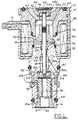
- Fig. 1 is a longitudinal cross-sectional view through a solenoid valve embodying a fluid flow restrictor according to the invention.
- Fig. 2 is an axial end view of one of the elements of the solenoid valve of Fig. 1 shown by itself apart from the valve.
- Fig. 3 is a transverse cross-sectional view taken in the direction of arrows 3-3 in Fig. 2.
- Fig. 4 is a view of the opposite axial end of Fig. 2.
- Fig. 5 is an axial end view of the fluid flow restrictor element by itself apart from the valve of Fig. 1.
- Fig. 6 is a longitudinal cross-sectional view taken in the direction of arrows 6-6 in Fig. 5
- Fig. 7 is a longitudinal view of the fluid flow restrictor element.
- Fig. 1 illustrates a solenoid valve 10 which comprises: a solenoid coil 12; two valve body pieces 14 and 16; an armature assembly 18 which consists of an armature piece 20 and a needle, or shaft, 22; and a helical coil spring 24.
- the valve has plural ports 26, 28, and 30, and internal passageway structure that communicates the ports.
- Solenoid coil 12 comprises a length of magnet wire that is wound into a tubular coil 32.
- Coil 32 is itself encapsulated within a suitable encapsulating material 34 so that the solenoid coil also possesses a tubular shape.
- the ends of the wire forming coil 32 are connected to respective wires 35 that are brought out of encapsulating material 34 to provide for the electrical connection of the solenoid coil in a suitable electrical control circuit (not shown) for selectively energizing the solenoid coil.
- Valve body piece 14 is constructed such that one axial end thereof fits into one axial end of solenoid coil 12; valve body piece 16 is constructed such that one axial end thereof fits into the opposite axial end of solenoid coil 12. O-ring seals 36 and 38 provide fluid-tight joints for these fits.
- Valve body piece 14 comprises a multiple shouldered central circular through-bore 40. A segment of this through-bore provides a guide bore for armature piece 20. A shim member 42, a seat member 44, and an orifice plate member 46 are secured within through-bore 40 at port 26. Spring 24 is arranged between valve body piece 16 and armature piece 20 for resiliently biasing armature assembly 18 toward valve body piece 14.
- Valve body piece 16 comprises a multiple shouldered central circular through-bore 48 within which are secured a needle guide member 50 and a seat member 52.
- a fluid flow restrictor element 54 is force-fitted within through-bore 48, as is a tubular element 56 that supports a transverse filter screen 57 across port 30.
- a tubular shell 58 surrounds solenoid coil 12 and has its opposite axial ends staked to valve body pieces 14 and 16 in the manner shown.
- the solenoid valve also mounts external O-ring seals 60, 62, and 64 in the manner shown for sealing of the solenoid valve to the fluid circuit with which it is intended to be used.
- a filter element 66 covers port 28 and is held in place by retention band structure 68.
- the internal fluid passageway structure comprises a skewed bore 70 which extends from port 28 to intercept through-bore 48 at a location which is between spring 24 and needle guide member 50, and a straight radial bore 72 which extends from port 28 to intercept through-bore 48 at a location adjacent the more interior axial end of restrictor element 54.
- Fig. 1 The position depicted by Fig. 1 is for solenoid coil 12 not electrically energized, and in this position spring 24 forces one axial end of needle 22 into seating engagement with seat member 44 while the opposite axial end of needle 22 is unseated from seat member 52.
- the spacing distance between the end of needle 22 and seat member 52 is somewhat exaggerated for illustrative purposes.
- flow restrictor element 54 While details of flow restrictor element 54 are disclosed in Figs. 5-7 and will be explained later on, it may for the moment be said that the cooperative effect between the flow restrictor element and the wall of that segment of through-bore 48 within which it is disposed is to create two parallel flow paths, one of which is relatively more restricted and the other of which is relatively less restricted.
- a relatively more restricted flow path extends between ports 28 and 30 and includes a series of restrictions that exists between the outside of element 54 and the wall of the segment of through-bore 48 containing the element.
- a relatively less restricted flow path between ports 28 and 30 is via a central circular through-hole 74 in element 54, and for the position illustrated by Fig. 1 where needle 22 is unseated from seat member 52, the relatively less restricted flow path continues from element 54 through members 52 and 50, through through-bore 48, and through skewed bore 70.
- armature assembly 18 When solenoid coil 12 is suitable electrically energized, armature assembly 18 is displaced from the illustrated position to unseat needle 22 from seat member 44 and to close the relatively less restricted parallel flow path between ports 28 and 30 by seating the needle on seat member 52.
- Armature piece 20 possesses a novel construction for improved valve response, particularly in high pressure applications, and where the available voltage for operating the solenoid may drop significantly below the nominal operating potential.
- armature piece 20 may be said to comprises a "hat-shaped" configuration. As disclosed in full detail by Figs. 2-4, this construction is embodied by a circular cylindrical main body 76 that is surrounded at one axial end by a circular flange 78.
- a central circular hole 80 for needle 22 passes completely through armature piece 20 and contains a circular counterbore 82 at the same axial end as flange 78. This counterbore forms a spring seat for one end of spring 24. The other end of the spring seats in a counterbore 85 as shown in Fig. 1.
- Armature piece 20 and needle 22 are joined by an suitable means to form the armature assembly 18.
- a number of channels therein provide for passage of fluid past armature piece 20.
- Channels 84 are open toward body piece 16 and are spaced ninety degrees apart about the armature's longitudinal axis.
- Each channel 84 extends from a point of communication with counterbore 82 to the radially outer edge surface of flange 78.
- axial channels 86 that extend completely through flange 78. These channels are spaced ninety degrees apart around the armature piece and each is in communication with the radially outer end of a corresponding channel 84, and is open toward the wall of through-bore 40.
- Channels 88 extend from flange 78 axially along the length of main body 76 to the end opposite flange 78. Channels 88 are arranged ninety degrees apart and are in circumferential registry with channels 84 and 86. As can be seen in Fig. 1, the organization and arrangement of solenoid coil 12 and valve body parts 14 and 16 are such that an interior space 90 is provided between parts 14 and 16 and this space is bounded by an annular wall surface of the encapsulating material 34. Flange 78 is disposed within this space, preferably in slightly inwardly spaced relation to the encapsulation surface.
- each channel 88 is shaped to comprise a taper that becomes radially larger in the direction away from the flange. This taper ceases at a location where the radial dimension of the channel becomes constant. This shape is intended to promote smooth axial flow as the fluid passes along the armature.
- Armature piece 20, body pieces 14 and 16, and shell 58 are of magnetically permeable material.
- a working gap 92 exists between the juxtaposed faces of armature piece 20 and valve body piece 16. With solenoid coil 12 not energized, this working gap has a maximum axial dimension; when the solenoid coil is suitably energized, the magnetic flux acts to attract armature piece 20 toward valve body piece 16 with the result that the axial dimension of the working gap is reduced.
- the construction of the armature piece is advantageous because the flange 78 can conduct a portion of the magnetic flux that would otherwise stray from the magnetically saturated permeable material of the armature piece.
- Flange 78 serves to augment the attractive force that is exerted on the armature assembly when the solenoid coil is energized. Yet, the organization and arrangement is also advantageous at solenoid coil de-energization.
- the presence of flange 78 allows the channel structure to be incorporated into armature piece 20, and so the fluid passageways that are provided by the channel structure in the armature piece attenuate the fluid's stiction effects and residual magnetic field break-down on the armature motion so that spring 24 will be capable of quickly releasing its stored energy with maximum effectiveness when the solenoid coil is de-energized.
- shim member 42 which can also perform a needle guide function, and it may be noticed that member 42 contains one or more holes 42a to allow fluid to pass freely through itself.
- restrictor element 54 comprises a circular cylindrical central core 94 that has a plurality of axially spaced apart flanges 96a, 96b, 96c, 96d, 96e, 96f, 96g, 96h, 96i that are integral with core 94.
- a series of axially spaced apart annular gaps 98a, 98b, 98c, 98d, 98e, 98f, 98g, 98h are thereby provided.
- Each flange 96a, 96b, 96c, 96d, 96e, 96f, 96g, 96h has a circularly contoured radially outer edge surface that is interrupted by at least one axially extending through-notch.
- the through-notches 100 of each flange are in circumferential registry with those of the other three flanges.
- Each through-notch 100 is open in the radially outward direction and has spaced apart parallel side edge surfaces which are bridged by a root edge surface so that the shape is generally rectangular.
- each of the flanges 96e, 96f, 96g, 96h there is only a single through-notch 102, and the through-notches 102 of immediately consecutive flanges are diametrically opposite each other about the central longitudinal axis of the restrictor element, and are also out of registry with the through-notches 100 by forty-five degrees.
- Each through-notch 102 has a single edge surface that lies on a chord of an imaginary circle that defined by the circularly contoured outer edge surface of its flange.
- Flange 96i has a circumferentially continuous, uninterrupted circular edge surface.
- the restrictor element is designed for a force fit with the wall of that segment of through-bore 48 within which it is disposed.
- the perimeter of each flange may be considered as essentially sealed to the through-bore wall except where it is interrupted by a through-notch.
- the four through-notches 100 of each flange 96a, 96b, 96c, 96d have a much greater total area than does the single through-notch 102 of each flange 96e, 96f, 96g, 96h.
- the end flange 96i forms a complete closure with the wall of the through-bore since it lacks any through-notch.
- Part 56 contains suitable notches at its interior axial end to provide fluid communication of port 30 to the through-notches 100 of flange 96a. From there communication with port 28 takes place through the through-notches 100, 102 and gaps 98, the gap 98h being in communication with radial bore 72.
- Restrictor element 54 is advantageously fabricated by die casting or plastic molding techniques so that it has a unitary one-piece construction, as distinguished from the multi-piece stacked disc construction of prior restrictors. By selection of a suitable material it is possible for the restrictor element to better compensate for temperature-induced fluid viscosity changes than prior restrictors.
- restrictor element that has been illustrated is exemplary.
- the number of flanges and the sizes and locations of the various through-notches will be a function of the particular specifications with which the restrictor element must comply when in use.
- a restrictor element must be available in certain different models, it is possible to satisfy different model requirements by fabricating a complete restrictor element as one model, and then shearing off a portion of the length of the complete element to yield a shorter length model having the appropriate number of flanges for achieving the desired restrictive effect, or by using multiple inserts in the mold.
- valve 10 that is illustrated in Fig. 1 is intended for use in one specific automotive ABS system, and is sometimes referred to as a two-way valve, either with or without a restrictor.
- the valve may be generally described as a vented two-way valve.
- needle 22 is unseated from seat member 52 so that what amounts to an unrestricted flow path exists between ports 28 and 30.
- This unrestricted flow path extends from port 30, through screen 57, through part 56, through through-hole 74, through a central hole 52a in member 52, through a pattern of holes 50a in member 50, through through-bore 48, through skewed bore 70, and through screen 66 to port 28.
- valve configurations are also contemplated, for example a three-way pulse width modulated valve. These other configurations may involve various modifications of the construction illustrated in Fig. 1. Such modifications may include changes to and/or relocations and/or omissions of one or more of the valve's parts, such as members 42, 44, 46, 50, 52, 54.
Landscapes
- Engineering & Computer Science (AREA)
- Physics & Mathematics (AREA)
- Mechanical Engineering (AREA)
- General Engineering & Computer Science (AREA)
- Electromagnetism (AREA)
- Fluid Mechanics (AREA)
- Transportation (AREA)
- Magnetically Actuated Valves (AREA)
Applications Claiming Priority (2)
| Application Number | Priority Date | Filing Date | Title |
|---|---|---|---|
| US646301 | 1991-01-28 | ||
| US07/646,301 US5102095A (en) | 1991-01-28 | 1991-01-28 | Flow restrictor for solenoid valve |
Publications (1)
| Publication Number | Publication Date |
|---|---|
| EP0497146A1 true EP0497146A1 (fr) | 1992-08-05 |
Family
ID=24592525
Family Applications (1)
| Application Number | Title | Priority Date | Filing Date |
|---|---|---|---|
| EP92100596A Withdrawn EP0497146A1 (fr) | 1991-01-28 | 1992-01-15 | Limitateur de flux pour électrovanne |
Country Status (2)
| Country | Link |
|---|---|
| US (1) | US5102095A (fr) |
| EP (1) | EP0497146A1 (fr) |
Cited By (4)
| Publication number | Priority date | Publication date | Assignee | Title |
|---|---|---|---|---|
| EP0655375A3 (fr) * | 1993-11-27 | 1995-08-02 | Lucas Ind Plc | Valves de commande actionnées magnétiquement pour l'écoulement de fluide. |
| EP0989345A3 (fr) * | 1998-09-22 | 2001-03-28 | Saturn Electronics & Engineering, Inc. | Soupape de régulation de la pression électromagnétique mono-étage avec moteur à force variable |
| WO2013060560A1 (fr) * | 2011-10-26 | 2013-05-02 | Robert Bosch Gmbh | Électrovanne et procédé pour le montage d'une électrovanne |
| CN106598089A (zh) * | 2016-11-11 | 2017-04-26 | 浙江沁园水处理科技有限公司 | 多功能废水比例器 |
Families Citing this family (15)
| Publication number | Priority date | Publication date | Assignee | Title |
|---|---|---|---|---|
| SE467419B (sv) * | 1990-11-14 | 1992-07-13 | Uniroc Ab | Borrstraengkomponent |
| US5192048A (en) * | 1992-06-26 | 1993-03-09 | Siemens Automotive L.P. | Fuel injector bearing cartridge |
| US5261637A (en) * | 1992-07-07 | 1993-11-16 | Lectron Products, Inc. | Electrical variable orifice actuator |
| IL110656A (en) * | 1994-08-14 | 1998-04-05 | Unitrol Amcor Ltd | Shut-off in shower apparatus |
| DE4429211A1 (de) * | 1994-08-18 | 1996-02-22 | Bosch Gmbh Robert | Elektromagnetisch betätigtes Ventil, insbesondere für schlupfgeregelte hydraulische Bremsanlagen in Kraftfahrzeugen |
| US5725023A (en) * | 1995-02-21 | 1998-03-10 | Lectron Products, Inc. | Power steering system and control valve |
| DE19751333A1 (de) * | 1996-11-20 | 1998-06-04 | Aisin Seiki | Durchflußregelventileinheit |
| US5839469A (en) * | 1997-02-12 | 1998-11-24 | Kold Ban International, Ltd. | Solenoid valve for starting fluid injection system |
| US6464153B1 (en) * | 2000-10-12 | 2002-10-15 | Delphi Technologies, Inc. | Fuel injector having a molded shroud formed of a structural adhesive polymer |
| US6877714B2 (en) * | 2003-05-08 | 2005-04-12 | The Toro Company | Flow control valve having differently configured labyrinths to select closing speed |
| US20060219815A1 (en) * | 2005-04-05 | 2006-10-05 | The Toro Company | Nonlinear increasing bypass stator |
| DE102008028564A1 (de) * | 2007-07-03 | 2009-01-08 | Luk Lamellen Und Kupplungsbau Beteiligungs Kg | Hydrauliksystem zum Erzeugen eines Vorsteuerdruckes zum Ansteuern einer Getriebekomponente |
| US7552719B2 (en) * | 2007-12-04 | 2009-06-30 | Caterpillar Inc. | Solenoid assembly having slotted stator |
| US8851444B2 (en) * | 2009-02-27 | 2014-10-07 | Parker-Hannifin Corporation | Pump flow restricting device |
| KR102008824B1 (ko) | 2012-06-21 | 2019-08-08 | 보르그워너 인코퍼레이티드 | 침지형 솔레노이드 밸브 |
Citations (4)
| Publication number | Priority date | Publication date | Assignee | Title |
|---|---|---|---|---|
| US4050479A (en) * | 1975-06-27 | 1977-09-27 | Masoneilan International, Inc. | Fluid resistance device |
| GB2066984A (en) * | 1980-01-04 | 1981-07-15 | Hopkinsons Ltd | A pressure reducing device |
| EP0342091A1 (fr) * | 1988-05-10 | 1989-11-15 | BENDIX EUROPE Services Techniques S.A. | Valve pilotée pour système d'antiblocage de roues |
| EP0401904A1 (fr) * | 1989-05-31 | 1990-12-12 | Target Rock Corporation | Dispositif programmable de réduction pour l'étranglement de fluide sous pression |
Family Cites Families (3)
| Publication number | Priority date | Publication date | Assignee | Title |
|---|---|---|---|---|
| US1086260A (en) * | 1912-06-13 | 1914-02-03 | Franz Abels | Steam-trap. |
| IT8123634U1 (it) * | 1981-11-26 | 1983-05-26 | Bravo Genesio | Dispositivo omogeneizzatore perfezionato, in particolare per la produzione di panna montata. |
| EP0100310B1 (fr) * | 1982-02-01 | 1986-11-12 | Caterpillar Inc. | Reducteur du debit dans un chemin de circuit |
-
1991
- 1991-01-28 US US07/646,301 patent/US5102095A/en not_active Expired - Fee Related
-
1992
- 1992-01-15 EP EP92100596A patent/EP0497146A1/fr not_active Withdrawn
Patent Citations (4)
| Publication number | Priority date | Publication date | Assignee | Title |
|---|---|---|---|---|
| US4050479A (en) * | 1975-06-27 | 1977-09-27 | Masoneilan International, Inc. | Fluid resistance device |
| GB2066984A (en) * | 1980-01-04 | 1981-07-15 | Hopkinsons Ltd | A pressure reducing device |
| EP0342091A1 (fr) * | 1988-05-10 | 1989-11-15 | BENDIX EUROPE Services Techniques S.A. | Valve pilotée pour système d'antiblocage de roues |
| EP0401904A1 (fr) * | 1989-05-31 | 1990-12-12 | Target Rock Corporation | Dispositif programmable de réduction pour l'étranglement de fluide sous pression |
Cited By (4)
| Publication number | Priority date | Publication date | Assignee | Title |
|---|---|---|---|---|
| EP0655375A3 (fr) * | 1993-11-27 | 1995-08-02 | Lucas Ind Plc | Valves de commande actionnées magnétiquement pour l'écoulement de fluide. |
| EP0989345A3 (fr) * | 1998-09-22 | 2001-03-28 | Saturn Electronics & Engineering, Inc. | Soupape de régulation de la pression électromagnétique mono-étage avec moteur à force variable |
| WO2013060560A1 (fr) * | 2011-10-26 | 2013-05-02 | Robert Bosch Gmbh | Électrovanne et procédé pour le montage d'une électrovanne |
| CN106598089A (zh) * | 2016-11-11 | 2017-04-26 | 浙江沁园水处理科技有限公司 | 多功能废水比例器 |
Also Published As
| Publication number | Publication date |
|---|---|
| US5102095A (en) | 1992-04-07 |
Similar Documents
| Publication | Publication Date | Title |
|---|---|---|
| US5102095A (en) | Flow restrictor for solenoid valve | |
| US4540154A (en) | Solenoid valve | |
| EP0526471B1 (fr) | Vanne de commande de fluide | |
| US4655255A (en) | Electromagnetically-operated multi-way valve | |
| US6179268B1 (en) | Proportional variable force solenoid control valve with segmented permanent magnet | |
| US5083747A (en) | Hat shaped armature for solenoid valve | |
| EP0055518B1 (fr) | Electrovanne | |
| EP0149239B1 (fr) | Valve à commande électromagnétique | |
| US6994406B1 (en) | EHB proportional solenoid valve with stepped gap armature | |
| US4988967A (en) | Solenoid operated hydraulic control valve | |
| US5443309A (en) | Solenoid valve, in particular for hydraulic brake systems with slip control | |
| KR100599023B1 (ko) | 슬립 방지 유압식 차량 브레이크 시스템용 전자기 장치 | |
| US5782267A (en) | Solenoid valve for an anti-lock brake system and valve fabricating method | |
| US20050099256A1 (en) | Solenoid and valve assembly having a linear output | |
| US20160240300A1 (en) | Solenoid apparatus | |
| US5064166A (en) | Solenoid valve with high flow capacity and low energy consumption | |
| US5618087A (en) | 2-position 3-way solenoid valve, modulator and anti-lock brake system with the valve | |
| US5311162A (en) | Solenoid device | |
| GB2124034A (en) | Solenoid valve | |
| JPH02147459A (ja) | 液圧ユニット | |
| US4694270A (en) | Electromagnetic proportional actuator | |
| EP0385286B1 (fr) | Régulateur de pression ayant un solénoide à force variable pour la commande électronique d'une transmission | |
| JP3082126B2 (ja) | 電磁弁装置 | |
| JP2003254469A (ja) | 弁内の流体圧を減衰する減衰室に流体リザーバを設ける方法及びその弁組合せ構造 | |
| WO2006065786A2 (fr) | Vanne d'isolement a actionnement manuel a commande magnetique |
Legal Events
| Date | Code | Title | Description |
|---|---|---|---|
| PUAI | Public reference made under article 153(3) epc to a published international application that has entered the european phase |
Free format text: ORIGINAL CODE: 0009012 |
|
| AK | Designated contracting states |
Kind code of ref document: A1 Designated state(s): DE FR GB |
|
| 17P | Request for examination filed |
Effective date: 19930122 |
|
| 17Q | First examination report despatched |
Effective date: 19940920 |
|
| STAA | Information on the status of an ep patent application or granted ep patent |
Free format text: STATUS: THE APPLICATION IS DEEMED TO BE WITHDRAWN |
|
| 18D | Application deemed to be withdrawn |
Effective date: 19950131 |