EP0497273A2 - Récipient d'emballage destiné à recevoir plusieurs objets - Google Patents
Récipient d'emballage destiné à recevoir plusieurs objets Download PDFInfo
- Publication number
- EP0497273A2 EP0497273A2 EP92101349A EP92101349A EP0497273A2 EP 0497273 A2 EP0497273 A2 EP 0497273A2 EP 92101349 A EP92101349 A EP 92101349A EP 92101349 A EP92101349 A EP 92101349A EP 0497273 A2 EP0497273 A2 EP 0497273A2
- Authority
- EP
- European Patent Office
- Prior art keywords
- packaging container
- base
- stack structure
- container according
- folded
- Prior art date
- Legal status (The legal status is an assumption and is not a legal conclusion. Google has not performed a legal analysis and makes no representation as to the accuracy of the status listed.)
- Granted
Links
- 238000004806 packaging method and process Methods 0.000 title claims abstract description 58
- 235000019219 chocolate Nutrition 0.000 claims abstract description 18
- 238000005192 partition Methods 0.000 claims description 23
- 230000037431 insertion Effects 0.000 claims 1
- 238000003780 insertion Methods 0.000 claims 1
- 239000000463 material Substances 0.000 abstract description 3
- 235000009508 confectionery Nutrition 0.000 abstract description 2
- 239000004033 plastic Substances 0.000 description 4
- 229920001169 thermoplastic Polymers 0.000 description 2
- 238000004026 adhesive bonding Methods 0.000 description 1
- 238000010276 construction Methods 0.000 description 1
- 238000006073 displacement reaction Methods 0.000 description 1
- 238000004049 embossing Methods 0.000 description 1
- 238000002347 injection Methods 0.000 description 1
- 239000007924 injection Substances 0.000 description 1
- 238000001746 injection moulding Methods 0.000 description 1
- 239000004416 thermosoftening plastic Substances 0.000 description 1
- 239000002699 waste material Substances 0.000 description 1
- 238000003466 welding Methods 0.000 description 1
Images



Classifications
-
- B—PERFORMING OPERATIONS; TRANSPORTING
- B65—CONVEYING; PACKING; STORING; HANDLING THIN OR FILAMENTARY MATERIAL
- B65D—CONTAINERS FOR STORAGE OR TRANSPORT OF ARTICLES OR MATERIALS, e.g. BAGS, BARRELS, BOTTLES, BOXES, CANS, CARTONS, CRATES, DRUMS, JARS, TANKS, HOPPERS, FORWARDING CONTAINERS; ACCESSORIES, CLOSURES, OR FITTINGS THEREFOR; PACKAGING ELEMENTS; PACKAGES
- B65D19/00—Pallets or like platforms, with or without side walls, for supporting loads to be lifted or lowered
- B65D19/38—Details or accessories
- B65D19/44—Elements or devices for locating articles on platforms
-
- B—PERFORMING OPERATIONS; TRANSPORTING
- B65—CONVEYING; PACKING; STORING; HANDLING THIN OR FILAMENTARY MATERIAL
- B65D—CONTAINERS FOR STORAGE OR TRANSPORT OF ARTICLES OR MATERIALS, e.g. BAGS, BARRELS, BOTTLES, BOXES, CANS, CARTONS, CRATES, DRUMS, JARS, TANKS, HOPPERS, FORWARDING CONTAINERS; ACCESSORIES, CLOSURES, OR FITTINGS THEREFOR; PACKAGING ELEMENTS; PACKAGES
- B65D5/00—Rigid or semi-rigid containers of polygonal cross-section, e.g. boxes, cartons or trays, formed by folding or erecting one or more blanks made of paper
- B65D5/42—Details of containers or of foldable or erectable container blanks
- B65D5/44—Integral, inserted or attached portions forming internal or external fittings
- B65D5/48—Partitions
- B65D5/48024—Partitions inserted
- B65D5/4804—Partitions inserted formed by folding strips essentially in tubes, U- or S-shape
-
- Y—GENERAL TAGGING OF NEW TECHNOLOGICAL DEVELOPMENTS; GENERAL TAGGING OF CROSS-SECTIONAL TECHNOLOGIES SPANNING OVER SEVERAL SECTIONS OF THE IPC; TECHNICAL SUBJECTS COVERED BY FORMER USPC CROSS-REFERENCE ART COLLECTIONS [XRACs] AND DIGESTS
- Y02—TECHNOLOGIES OR APPLICATIONS FOR MITIGATION OR ADAPTATION AGAINST CLIMATE CHANGE
- Y02W—CLIMATE CHANGE MITIGATION TECHNOLOGIES RELATED TO WASTEWATER TREATMENT OR WASTE MANAGEMENT
- Y02W30/00—Technologies for solid waste management
- Y02W30/50—Reuse, recycling or recovery technologies
- Y02W30/80—Packaging reuse or recycling, e.g. of multilayer packaging
Definitions
- the invention relates to a packaging container for holding a plurality of objects, in particular chocolate bars, according to the preamble of claim 1.
- Packaging containers of the type mentioned here are referred to in the technical jargon as "shops". They serve as a means of transport and presentation of objects arranged therein in several stacks, in particular packaged confectionery, such as chocolate bars. These goods are therefore brought to the dealer in the packaging containers and sold out of the packaging containers.
- Known packaging containers of this type generally allow only one use.
- the packaging containers must therefore be disposed of after the goods in them have sold off. Because of the size of the packaging containers having a pallet-like shape, this results in a large amount of waste.
- the object of the invention is to create a packaging container of the type mentioned at the outset which can be reused in a simple manner.
- the packaging container has the features of claim 1. Because the stack structure can be detached from the base, the base, which requires only a relatively small amount of space, can be easily transported back for the purpose of multiple use (reusable principle). Due to the foldable and unfoldable design of the stack structure, this can also be transported back in a space-saving manner and then reconnected to the base. The entire packaging container is therefore reusable.
- the stack structure can be folded or folded such that the base area of the folded or folded stack structure corresponds approximately to the base area of the base, and is preferably slightly smaller.
- the collapsed or folded stack structure can be placed on or in the base. The entire packaging container can thus be transported back in a space-saving manner.
- the stack structure consists of a plurality of upright partition walls, some of which are pivotably arranged around at least one preferably central (hollow) column.
- the column stabilizes the stack structure and facilitates the pivoting of the partition walls to fold and / or fold the stack structure.
- the construction of the stack structure by the column is also simplified.
- the column is preferably formed from two adjacent partial columns. These are connected to one another in such a way that the two sub-columns can be pivoted apart from their sides facing each other in order to fold up the stack structure. At the same time, the two sub-columns are folded together to save space, i.e. converted from a three-dimensional to a flat shape.
- the partial columns are connected to one another by a part of the stack structure forming two partitions.
- This part of the stack structure also has a center fold line forming a central hinge axis, which lies between the side surfaces of the sub-columns connected to one another.
- this central hinge axis By means of this central hinge axis, the folded or laid stack structure can be folded in the middle (approximately V-shaped). This allows the base area of the folded or folded stack structure to be halved.
- the expanded or erected stack structure is expediently connected to the base by at least one plug connection.
- This is preferably formed from depressions formed corresponding to the floor plan of the stack structure. In this way, the stack structure with lower edge sections can be easily and reliably inserted into the base by positive locking.
- supports for the objects to be stacked on the partitions of the stack structure are arranged in such a way that they are inclined towards the central column.
- the stacked objects are securely held in the packaging container because the inclination of the supports pushes the objects against the partitions of the stack structure or the column. Even higher stacks of objects lying on top of each other cannot fall out.
- the base is formed from an outer part and at least one inner part.
- a base is particularly easy to produce because the separate inner part can easily be provided with the inclined supports or partial support surfaces for the objects to be stacked in the packaging container and the recesses for inserting the folded stack-up structure can be formed by simple longitudinal and transverse slots in the inner part .
- the inner part can be formed in one or more pieces. In the case of multi-part inner parts, the individual pieces of the same extend to those areas of the base which are located either between two parallel dividing walls or two mutually perpendicular dividing walls (in corner areas of the packaging container).
- the entire packaging container is formed from a durable material that enables multiple uses.
- Both the base and the stack structure are preferably made of plastic, preferably thermoplastic. Due to this selection of materials, the packaging container according to the invention is particularly robust and can therefore be reused almost indefinitely.
- the plastic packaging container according to the invention can be produced particularly easily by deep drawing, injection molding and / or cutting from semi-finished panels.
- the invention relates to a packaging container with which chocolate bars 10 are brought onto the market as a "reusable shop” and then sold off.
- the packaging container is designed such that a plurality of stacks of a plurality of chocolate bars 10 lying one above the other can be accommodated therein.
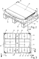
- the outer sides of the packaging container are open, so that the chocolate bars 10 packed therein are easily accessible from the outside (FIG. 1).
- the packaging container is formed from a base 11 and a stack structure 12 releasably connected thereto.
- the stack structure 12 can be folded.
- the base 11 is formed in two parts in the packaging container shown here. It is composed of an outer part 13 and an inner part 14.
- the outer part 13 of the base 11 has the shape of a low-sided box open at the top. Accordingly, the outer part 13 has a closed base 15 with a rectangular base here and (low) side walls 16 and transverse walls 17 adjoining the edges of the base 15. These are directed perpendicular to the base 15 and completely surround the latter. In the corner areas, the side walls 16 and transverse walls 17 are expanded upwards to form stacking corners 18 (FIG. 1). Under the floor 15 there are projections 19 which are designed to correspond to the stacking corners 18, specifically here as L-shaped ribs. The ribs are set back from the edge of the bottom 15 by the measure of the wall thickness of the stacking corners 18 (FIGS. 4 and 5).
- each outer part 13 serves to secure the packaging container with the base 11 on a standardized pallet 20 (FIG. 1) against slipping.
- the projections 19 engage in depressions on the upper side of the pallet 20.
- the inner part 14 is designed in the manner of an insert which is received in the outer part 13 and is held here in a form-fitting manner between the side walls 16 and transverse walls 17.
- the one-piece inner part here 14 are arranged from one side to the other through grooves, namely two parallel longitudinal grooves 21 and two parallel transverse grooves 22 (Fig. 3). These divide the base area of the inner part 14 into a total of nine fields 23 to 26.
- the longitudinal grooves 21 and transverse grooves 22 are closed by webs 54.
- the fields 23 to 26 of the inner part 14 are connected to one another in one piece by these.
- the fields 23 to 25 form support surfaces for one or more stacks of chocolate bars 10.
- the four similarly designed corner-side fields 23 serve to accommodate four stacks each with chocolate bars 10 adjacent to one another on their long sides.
- Two fields 24 serve to accommodate six each adjacent and successive stacks.
- Two small fields 25 are provided for one stack each.
- a central field 26 enclosed by the outer fields 23 to 25 remains free, that is to say it is unpacked, because the fields 23, 24, 25 arranged around it do not allow access to the chocolate bars 10 from the outside (FIG. 3).
- the supports of the fields 23 to 25 of the inner part 14 which serve to receive the stack of chocolate bars 10 lying one above the other run inclined to the base 15 of the base 11. This inclination is chosen such that it runs towards the flat base of the central field 26. As a result, the chocolate bars 10 are inclined slightly downwards towards the central field 26 in the packaging container, thereby preventing the stack of chocolate bars 10 lying one above the other from shifting to the open outer sides of the packaging container and thereby being able to fall over.
- the supports of the fields 24 have a continuous plane that is inclined to the middle field 26.
- the supports of the corner-side fields 23 are formed in a scale-like manner, namely formed from four successive partial supports 27 for a stack of chocolate bars 10 one above the other.
- Each partial support 27 is inclined downwards towards the field 25.
- the fields 23 are therefore sawtooth-shaped (FIGS. 1 and 4).
- the partial surfaces are continuously inclined towards the fields 24.
- the partial supports 27 are aligned overall to the respective corner of the central field 26, as a result of which a stable reception of the stacks of chocolate bars 10 lying one above the other is also ensured in the corner-side fields 23.
- the stack structure 12 is not only detachably connected to the base 11; rather, it can also be folded or folded after being removed from the base 11.
- the stack structure 12 has a central column 28, the base area of which is designed to correspond to the base area of the field 26.
- Each side of the central column 28 is extended at opposite ends by a partition wall 29, 30, 31 and 32, respectively.
- the central column 28 is connected to four pairs of partition walls 29, 30, 31 and 32, respectively.
- the partitions 29, 31, 32 are articulated, namely articulated to the central column 28 by means of upright hinge axes 33.
- the two partitions 30, however, are rigidly connected to the central column 28.
- the longitudinal grooves 21 and transverse grooves 22 in the inner part 14 are dimensioned such that their width and depth correspond to the wall thickness of the partitions 29 to 32, so that the folded stack structure 12 can be inserted into the longitudinal grooves 21 and transverse grooves 22 of the inner part 14 from above .
- the central column 28 is divided in the middle.
- the central column 28 is composed of two hollow sub-columns 35 and 36 of the same size.
- the sub-columns 35 and 36 are connected to one another (FIGS. 1 and 6).
- the stack structure 12 shown here is formed from a total of nine blanks firmly connected to one another. Eight blanks are formed from four pairs of different blanks 38, 39, 40, 41, while a fifth blank 42 is only present.
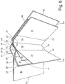
- the shape of the blanks 38..42 is described in more detail below with reference to the spread or unfolded stack structure 12 (FIGS. 6 and 7):
- the blank 40 and part of the blank 39 are used to form each sub-column 35 and 36.
- the blank 40 is angled L-shaped, while the blank 39 has a double L-shaped or Z-shaped shape.
- the L-shaped blank 40 forms two walls 43, 44 of the respective sub-column 35, 36, while two legs of each blank 39 running at right angles to one another form the two remaining walls 45 and 46 of each sub-column 35, 36.
- connecting tabs 47 and 48 are arranged, which connect the walls 43 and 44 of the blank 40 to the walls 45 and 46 of the blank 39.
- a third leg of the blank 39 forms one half of the dividing wall 29.
- a second half of this dividing wall 29 is formed by a connecting tab 49 of the L-shaped blank 38 which completely overlaps and is fastened thereon.
- the second leg extending at right angles to the connecting tab 49 of each blank 38 forms a partition 32 in each case.
- a flat blank 41 is connected in each case in such a way that each blank 41 completely overlaps the corresponding wall 45 of the respective sub-column 35 and 36 and above protrudes outwards towards the partial columns 35, 36 to form the partition walls 30.
- the blank 42 is U-shaped. Two parallel legs of the blank 42 thereby form the same-sized, parallel partition walls 31.
- a web 50 of the blank 42 connecting the partition walls 31 corresponds to the width of the adjacent sub-columns 35 and 36 and overlaps the sections of the panels 41 adjacent to it
- the cut 41 runs an upright central hinge axis 51. This enables the partial columns 35 and 36 to be unfolded in the region of their corners 37 and to halve the total area of the folded or folded stack structure 12.
- the stack structure 12 is folded up by pivoting individual sections of the blanks 38, 39, 40 and 42 about their hinge axes 33 or the central hinge axis 51.
- the hinge axes 33 or the central hinge axis 51 are shown in FIGS Blanks 38 to 40 and 42 formed by embossing or the like.
- the stack structure 12 is folded or folded in the following manner (FIGS. 6 and 7): After the stack structure 12 has been detached from the base 11, the Z-shaped blanks 39 are flattened by pulling on their free ends, namely from the outside against the blanks 41 lying in the folding surface 34 and not changing in shape. At the same time, the blanks 40 are deformed in such a way that the partial columns 35 and 36 are flat. Subsequently, the opposite partitions 32 of the blanks 38 are unfolded in opposite directions, so that their free edges 52 are directed away from one another. Likewise, the partition walls 31 of the blank 42 are moved away from each other in opposite directions, so that their free edges 53 are located on opposite outer sides of the folded stack structure 12.
- the folded stack structure 12 is again folded in a V-shape around the central hinge axis 51 in order to halve its base area.
- the blanks 38 to 42 of the stack structure 12 receives a rectangular base area in the folded or folded state, which corresponds to the inside dimension of the outer part 13 of the base 11, whereby the folded stack structure 12 can be placed on the inner part 14 of the base 11 and thereby being positively received.
- further folded packaging containers can be placed with their base 11 on the stacking corners 18 of the lower base 11. In this way, several empty and collapsed packaging containers can be transported back to save space for refilling.
- the entire packaging container is formed from plastic, and preferably from thermoplastic plastic.
- the outer part 13 of the base 11 is preferably designed as an injection molded part.
- the inner part 14 of the base 11 is preferably formed by deep drawing.
- the outer part 13 can also be designed as a deep-drawn part.
- the blanks 39 to 42 are preferably cut out of a sheet-shaped plastic.
- the hinge axes 33 and the central hinge axis 51 are produced by stamping so that they form film hinges.
- the blanks 39 to 42 are connected at their connecting tabs 47 to 49 by gluing, welding or the like.
Landscapes
- Engineering & Computer Science (AREA)
- Mechanical Engineering (AREA)
- Stackable Containers (AREA)
- Auxiliary Devices For And Details Of Packaging Control (AREA)
- Container Filling Or Packaging Operations (AREA)
- Packages (AREA)
- Packaging Of Annular Or Rod-Shaped Articles, Wearing Apparel, Cassettes, Or The Like (AREA)
Applications Claiming Priority (2)
| Application Number | Priority Date | Filing Date | Title |
|---|---|---|---|
| DE19914102569 DE4102569A1 (de) | 1991-01-29 | 1991-01-29 | Verpackungsbehaelter zur aufnahme einer mehrzahl von gegenstaenden |
| DE4102569 | 1991-01-29 |
Publications (3)
| Publication Number | Publication Date |
|---|---|
| EP0497273A2 true EP0497273A2 (fr) | 1992-08-05 |
| EP0497273A3 EP0497273A3 (en) | 1993-03-03 |
| EP0497273B1 EP0497273B1 (fr) | 1995-11-15 |
Family
ID=6423923
Family Applications (1)
| Application Number | Title | Priority Date | Filing Date |
|---|---|---|---|
| EP19920101349 Expired - Lifetime EP0497273B1 (fr) | 1991-01-29 | 1992-01-28 | Récipient d'emballage destiné à recevoir plusieurs objets |
Country Status (8)
| Country | Link |
|---|---|
| US (1) | US5201421A (fr) |
| EP (1) | EP0497273B1 (fr) |
| AT (1) | ATE130263T1 (fr) |
| CA (1) | CA2060136C (fr) |
| DE (2) | DE4102569A1 (fr) |
| DK (1) | DK0497273T3 (fr) |
| ES (1) | ES2079698T3 (fr) |
| GR (1) | GR3018103T3 (fr) |
Families Citing this family (13)
| Publication number | Priority date | Publication date | Assignee | Title |
|---|---|---|---|---|
| DE19618411C2 (de) * | 1996-05-08 | 2002-07-18 | Zeiss Carl Jena Gmbh | Verpackung zum Aufbewahren und zum Transport von stoß- und berührungsempfindlichen Fertigteilen |
| US6408768B1 (en) * | 1999-05-27 | 2002-06-25 | Safe Strap Company, Inc. | Adjustable pallet guard |
| US6270007B1 (en) * | 1999-08-24 | 2001-08-07 | Cherokee Manufacturing | Stackable transport crate |
| DE202006005651U1 (de) * | 2006-04-06 | 2006-07-27 | Schwaiger, Axel | Getränkekasten klappbar |
| US8434620B2 (en) * | 2010-08-10 | 2013-05-07 | Grafcor Packaging, Inc. | Bottle shipment packaging and method |
| US8991685B2 (en) | 2011-11-09 | 2015-03-31 | Rts Packaging Llc | Partition |
| US9156586B2 (en) * | 2012-08-31 | 2015-10-13 | Air Liquide America Specialty Gases Llc | Transport system for compressed gas cylinders |
| US10124924B2 (en) | 2016-08-08 | 2018-11-13 | Acorn West LLC | Beverage container packaging |
| US10435195B2 (en) * | 2017-08-09 | 2019-10-08 | Converter Manufacturing, Llc | Reinforced gaylord container |
| US20210094727A1 (en) * | 2018-02-13 | 2021-04-01 | Envases Chiloe S.A. | Arrangement of expanded polystyrene boxes and expanded polystyrene box for food transport and storage |
| US12116195B2 (en) * | 2019-09-18 | 2024-10-15 | Polymer Solutions International, Inc. | Water dispenser transport pallet assembly |
| US11261015B2 (en) | 2019-11-13 | 2022-03-01 | Acorn West LLC | Beverage container packaging |
| US11685570B2 (en) | 2020-05-15 | 2023-06-27 | Acorn West LLC | Thermal regulating lay flat beverage container packaging |
Family Cites Families (23)
| Publication number | Priority date | Publication date | Assignee | Title |
|---|---|---|---|---|
| DE7142123U (de) * | 1972-01-27 | Ferrero Gmbh | Verkaufsaufsteller fur Warenpackungen, insbesondere fur Suß oder Schokolade Warenpackungen | |
| US930835A (en) * | 1909-01-05 | 1909-08-10 | Luther P Brown | Collapsible carton. |
| US1456098A (en) * | 1920-10-28 | 1923-05-22 | Gen Electric | Packing case |
| US1704948A (en) * | 1925-11-07 | 1929-03-12 | Mid West Box Company | Container |
| US1802123A (en) * | 1927-06-03 | 1931-04-21 | Mohen John Patrick | Display carton |
| BE428551A (fr) * | 1937-06-12 | |||
| FR1314009A (fr) * | 1961-11-25 | 1963-01-04 | Chocolaterie D Aiguebelle | Boîte d'emballage et de présentation d'articles de forme parallélipipédique ou autre, analogue ou approchante |
| DE1511144A1 (de) * | 1962-02-23 | 1969-06-19 | Schenley Ind Inc | Schau- und Versandpackung,insbesondere fuer Flaschen |
| US3429427A (en) * | 1967-02-13 | 1969-02-25 | Western Publishing Inc | Crayon merchandising display box and container |
| US3628718A (en) * | 1969-06-13 | 1971-12-21 | Du Pont | Storage container |
| SU685567A1 (ru) * | 1978-04-20 | 1979-09-15 | Организвция П/Я В-2108 | Контейнер |
| JPS613767Y2 (fr) * | 1980-09-22 | 1986-02-05 | ||
| US4477016A (en) * | 1982-03-25 | 1984-10-16 | Federal Paper Board Company, Inc. | Cellular display structure |
| GB2150533B (en) * | 1983-11-28 | 1988-01-20 | Reed Int Plc | Box pallets |
| US4697699A (en) * | 1985-11-06 | 1987-10-06 | Tootsie Roll Industries, Inc. | Shipping container |
| US4643314A (en) * | 1986-05-27 | 1987-02-17 | Chrysler Motors Corporation | Container construction |
| US4763787A (en) * | 1986-06-02 | 1988-08-16 | Owens-Illinois Television Products Inc. | Package assembly |
| US4877137A (en) * | 1987-03-05 | 1989-10-31 | The Stanley Works | Display package module for promotional display use |
| JPS63272661A (ja) * | 1987-04-27 | 1988-11-10 | Sekisui Plastics Co Ltd | パレツト |
| DE8805701U1 (de) * | 1988-04-29 | 1988-09-15 | Nestlé Deutschland AG, 6000 Frankfurt | Palette zur Aufnahme und Lagerung von tafelartigen Gegenständen |
| DE9003424U1 (de) * | 1990-03-23 | 1990-06-13 | CDE Commerce Display Eichler GmbH, 2000 Hamburg | Sockel für Verkaufsaufsteller |
| DE9003423U1 (de) * | 1990-03-23 | 1990-06-13 | CDE Commerce Display Eichler GmbH, 2000 Hamburg | Sockel für Verkaufsaufsteller |
| US5004102A (en) * | 1990-07-30 | 1991-04-02 | Chrysler Corporation | Rack for transporting vehicle center console assemblies |
-
1991
- 1991-01-29 DE DE19914102569 patent/DE4102569A1/de not_active Withdrawn
-
1992
- 1992-01-28 AT AT92101349T patent/ATE130263T1/de not_active IP Right Cessation
- 1992-01-28 CA CA 2060136 patent/CA2060136C/fr not_active Expired - Fee Related
- 1992-01-28 EP EP19920101349 patent/EP0497273B1/fr not_active Expired - Lifetime
- 1992-01-28 US US07/826,730 patent/US5201421A/en not_active Expired - Lifetime
- 1992-01-28 ES ES92101349T patent/ES2079698T3/es not_active Expired - Lifetime
- 1992-01-28 DE DE59204285T patent/DE59204285D1/de not_active Expired - Fee Related
- 1992-01-28 DK DK92101349T patent/DK0497273T3/da active
-
1995
- 1995-11-16 GR GR950403112T patent/GR3018103T3/el unknown
Also Published As
| Publication number | Publication date |
|---|---|
| US5201421A (en) | 1993-04-13 |
| ES2079698T3 (es) | 1996-01-16 |
| CA2060136C (fr) | 2002-04-02 |
| EP0497273A3 (en) | 1993-03-03 |
| DE4102569A1 (de) | 1992-07-30 |
| EP0497273B1 (fr) | 1995-11-15 |
| DK0497273T3 (da) | 1996-03-04 |
| DE59204285D1 (de) | 1995-12-21 |
| GR3018103T3 (en) | 1996-02-29 |
| ATE130263T1 (de) | 1995-12-15 |
| CA2060136A1 (fr) | 1992-07-30 |
Similar Documents
| Publication | Publication Date | Title |
|---|---|---|
| DE2426723C3 (de) | Mit Folienscharnier klappbar ausgebildeter Eckverbinder für brettförmige Bauteile | |
| DE2933634A1 (de) | Packung fuer dosen o.dgl., sowie verfahren und zuschnitt zur formung derselben | |
| EP0497273B1 (fr) | Récipient d'emballage destiné à recevoir plusieurs objets | |
| DE69216227T2 (de) | Zusammenklappbarer Artikelträger mit abgeschrägter Seitenwandecken | |
| DE69426256T2 (de) | Stapelbarer behälter und zuschnittsstruktur zur seiner herstellung | |
| DE4003104A1 (de) | Verpackungsbehaelter, insbesondere zur aufnahme von schokoladenartikeln, und zuschnitt zur bildung desselben | |
| DE4143023C2 (de) | Klappbarer Rahmen für eine Transport- oder Lagerbox | |
| DE69513026T2 (de) | Ineinandersetzbarer behälter | |
| DE3915408C2 (de) | Verpackungsbehälter, insbesondere Tray, aus faltbarem Material | |
| DE3702673C2 (fr) | ||
| DE69601474T2 (de) | Faltschachtel und Zuschnitt dafür | |
| DE7807151U1 (de) | Ausklappbare Lieferkiste beispielsweise fuer Fisch | |
| EP0357817B1 (fr) | Rayonnage en bois à insertion de tablettes à des niveaux variables | |
| DE4140030C1 (en) | Foldable box with six walls and partitions - has one side wall coupled to single compartment bottom via fold line | |
| DE7904189U1 (de) | Stapelbarer Transportbehaelter | |
| DE29513265U1 (de) | Teilbare Verpackung aus Wellpappe oder Karton | |
| DE3811543A1 (de) | Faltschachtel | |
| DE3131427C2 (de) | Trennwandeinzatz für einen zur Aufnahme von Flaschen bestimmten Behälter | |
| DE29908663U1 (de) | Zweiteilige Verpackung aus faltbarem Material zum Verpacken von Einzelgut | |
| DE2356466B2 (de) | Stapelbare Verpackungspalette aus einem Kartonzuschnitt | |
| DE3318750A1 (de) | Behaelter mit offener oberseite | |
| DE29620886U1 (de) | Behälter | |
| DE10356825A1 (de) | Stapelbarer Transportbehälter aus Wellpappe und Zuschnitt dafür | |
| DE8806517U1 (de) | Stapelsteige mit säulenartigen Eckverstärkungen | |
| EP3053850A1 (fr) | Porte-bouteilles pliable en plastique |
Legal Events
| Date | Code | Title | Description |
|---|---|---|---|
| PUAI | Public reference made under article 153(3) epc to a published international application that has entered the european phase |
Free format text: ORIGINAL CODE: 0009012 |
|
| AK | Designated contracting states |
Kind code of ref document: A2 Designated state(s): AT BE CH DE DK ES FR GB GR IT LI LU MC NL PT SE |
|
| PUAL | Search report despatched |
Free format text: ORIGINAL CODE: 0009013 |
|
| AK | Designated contracting states |
Kind code of ref document: A3 Designated state(s): AT BE CH DE DK ES FR GB GR IT LI LU MC NL PT SE |
|
| RHK1 | Main classification (correction) |
Ipc: B65D 5/48 |
|
| 17P | Request for examination filed |
Effective date: 19930728 |
|
| 17Q | First examination report despatched |
Effective date: 19940825 |
|
| GRAA | (expected) grant |
Free format text: ORIGINAL CODE: 0009210 |
|
| AK | Designated contracting states |
Kind code of ref document: B1 Designated state(s): AT BE CH DE DK ES FR GB GR IT LI LU MC NL PT SE |
|
| PG25 | Lapsed in a contracting state [announced via postgrant information from national office to epo] |
Ref country code: MC Free format text: LAPSE BECAUSE OF NON-PAYMENT OF DUE FEES Effective date: 19951115 |
|
| REF | Corresponds to: |
Ref document number: 130263 Country of ref document: AT Date of ref document: 19951215 Kind code of ref document: T |
|
| GBT | Gb: translation of ep patent filed (gb section 77(6)(a)/1977) |
Effective date: 19951114 |
|
| REF | Corresponds to: |
Ref document number: 59204285 Country of ref document: DE Date of ref document: 19951221 |
|
| PGFP | Annual fee paid to national office [announced via postgrant information from national office to epo] |
Ref country code: GR Payment date: 19951227 Year of fee payment: 5 |
|
| PGFP | Annual fee paid to national office [announced via postgrant information from national office to epo] |
Ref country code: DK Payment date: 19960111 Year of fee payment: 5 |
|
| REG | Reference to a national code |
Ref country code: ES Ref legal event code: FG2A Ref document number: 2079698 Country of ref document: ES Kind code of ref document: T3 |
|
| PGFP | Annual fee paid to national office [announced via postgrant information from national office to epo] |
Ref country code: SE Payment date: 19960119 Year of fee payment: 5 |
|
| PGFP | Annual fee paid to national office [announced via postgrant information from national office to epo] |
Ref country code: PT Payment date: 19960129 Year of fee payment: 5 |
|
| PG25 | Lapsed in a contracting state [announced via postgrant information from national office to epo] |
Ref country code: LU Free format text: LAPSE BECAUSE OF NON-PAYMENT OF DUE FEES Effective date: 19960131 |
|
| REG | Reference to a national code |
Ref country code: GR Ref legal event code: FG4A Free format text: 3018103 |
|
| ITF | It: translation for a ep patent filed | ||
| REG | Reference to a national code |
Ref country code: CH Ref legal event code: NV Representative=s name: ISLER & PEDRAZZINI AG PATENTANWAELTE |
|
| ET | Fr: translation filed | ||
| REG | Reference to a national code |
Ref country code: DK Ref legal event code: T3 |
|
| SC4A | Pt: translation is available |
Free format text: 951123 AVAILABILITY OF NATIONAL TRANSLATION |
|
| PLBE | No opposition filed within time limit |
Free format text: ORIGINAL CODE: 0009261 |
|
| STAA | Information on the status of an ep patent application or granted ep patent |
Free format text: STATUS: NO OPPOSITION FILED WITHIN TIME LIMIT |
|
| 26N | No opposition filed | ||
| PG25 | Lapsed in a contracting state [announced via postgrant information from national office to epo] |
Ref country code: DK Effective date: 19970128 |
|
| REG | Reference to a national code |
Ref country code: DK Ref legal event code: EBP |
|
| PG25 | Lapsed in a contracting state [announced via postgrant information from national office to epo] |
Ref country code: SE Effective date: 19970129 |
|
| PG25 | Lapsed in a contracting state [announced via postgrant information from national office to epo] |
Ref country code: PT Effective date: 19970731 Ref country code: GR Free format text: THE PATENT HAS BEEN ANNULLED BY A DECISION OF A NATIONAL AUTHORITY Effective date: 19970731 |
|
| REG | Reference to a national code |
Ref country code: GR Ref legal event code: MM2A Free format text: 3018103 |
|
| EUG | Se: european patent has lapsed |
Ref document number: 92101349.6 |
|
| REG | Reference to a national code |
Ref country code: PT Ref legal event code: MM4A Free format text: LAPSE DUE TO NON-PAYMENT OF FEES Effective date: 19970731 |
|
| PGFP | Annual fee paid to national office [announced via postgrant information from national office to epo] |
Ref country code: DE Payment date: 19971230 Year of fee payment: 7 |
|
| PGFP | Annual fee paid to national office [announced via postgrant information from national office to epo] |
Ref country code: FR Payment date: 19980109 Year of fee payment: 7 |
|
| PGFP | Annual fee paid to national office [announced via postgrant information from national office to epo] |
Ref country code: AT Payment date: 19980114 Year of fee payment: 7 |
|
| PGFP | Annual fee paid to national office [announced via postgrant information from national office to epo] |
Ref country code: GB Payment date: 19980119 Year of fee payment: 7 |
|
| PGFP | Annual fee paid to national office [announced via postgrant information from national office to epo] |
Ref country code: NL Payment date: 19980128 Year of fee payment: 7 |
|
| PGFP | Annual fee paid to national office [announced via postgrant information from national office to epo] |
Ref country code: ES Payment date: 19980129 Year of fee payment: 7 |
|
| PGFP | Annual fee paid to national office [announced via postgrant information from national office to epo] |
Ref country code: CH Payment date: 19980206 Year of fee payment: 7 |
|
| PGFP | Annual fee paid to national office [announced via postgrant information from national office to epo] |
Ref country code: BE Payment date: 19980320 Year of fee payment: 7 |
|
| PG25 | Lapsed in a contracting state [announced via postgrant information from national office to epo] |
Ref country code: GB Free format text: LAPSE BECAUSE OF NON-PAYMENT OF DUE FEES Effective date: 19990128 Ref country code: AT Free format text: LAPSE BECAUSE OF NON-PAYMENT OF DUE FEES Effective date: 19990128 |
|
| PG25 | Lapsed in a contracting state [announced via postgrant information from national office to epo] |
Ref country code: ES Free format text: LAPSE BECAUSE OF NON-PAYMENT OF DUE FEES Effective date: 19990129 |
|
| PG25 | Lapsed in a contracting state [announced via postgrant information from national office to epo] |
Ref country code: LI Free format text: LAPSE BECAUSE OF NON-PAYMENT OF DUE FEES Effective date: 19990131 Ref country code: CH Free format text: LAPSE BECAUSE OF NON-PAYMENT OF DUE FEES Effective date: 19990131 Ref country code: BE Free format text: LAPSE BECAUSE OF NON-PAYMENT OF DUE FEES Effective date: 19990131 |
|
| BERE | Be: lapsed |
Owner name: S.A. KRAFT JACOBS SUCHARD Effective date: 19990131 |
|
| PG25 | Lapsed in a contracting state [announced via postgrant information from national office to epo] |
Ref country code: NL Free format text: LAPSE BECAUSE OF NON-PAYMENT OF DUE FEES Effective date: 19990801 |
|
| GBPC | Gb: european patent ceased through non-payment of renewal fee |
Effective date: 19990128 |
|
| REG | Reference to a national code |
Ref country code: CH Ref legal event code: PL |
|
| PG25 | Lapsed in a contracting state [announced via postgrant information from national office to epo] |
Ref country code: FR Free format text: LAPSE BECAUSE OF NON-PAYMENT OF DUE FEES Effective date: 19990930 |
|
| PG25 | Lapsed in a contracting state [announced via postgrant information from national office to epo] |
Ref country code: DE Free format text: LAPSE BECAUSE OF NON-PAYMENT OF DUE FEES Effective date: 19991103 |
|
| REG | Reference to a national code |
Ref country code: FR Ref legal event code: ST |
|
| REG | Reference to a national code |
Ref country code: ES Ref legal event code: FD2A Effective date: 20010503 |
|
| PG25 | Lapsed in a contracting state [announced via postgrant information from national office to epo] |
Ref country code: IT Free format text: LAPSE BECAUSE OF NON-PAYMENT OF DUE FEES;WARNING: LAPSES OF ITALIAN PATENTS WITH EFFECTIVE DATE BEFORE 2007 MAY HAVE OCCURRED AT ANY TIME BEFORE 2007. THE CORRECT EFFECTIVE DATE MAY BE DIFFERENT FROM THE ONE RECORDED. Effective date: 20050128 |