EP0497325A2 - Procédé pour la détermination de quantité d'UCR et appareil de traitement d'images - Google Patents
Procédé pour la détermination de quantité d'UCR et appareil de traitement d'images Download PDFInfo
- Publication number
- EP0497325A2 EP0497325A2 EP92101487A EP92101487A EP0497325A2 EP 0497325 A2 EP0497325 A2 EP 0497325A2 EP 92101487 A EP92101487 A EP 92101487A EP 92101487 A EP92101487 A EP 92101487A EP 0497325 A2 EP0497325 A2 EP 0497325A2
- Authority
- EP
- European Patent Office
- Prior art keywords
- ucr
- test pattern
- density
- image processing
- processing apparatus
- Prior art date
- Legal status (The legal status is an assumption and is not a legal conclusion. Google has not performed a legal analysis and makes no representation as to the accuracy of the status listed.)
- Granted
Links
- 238000012545 processing Methods 0.000 title claims description 48
- 238000000034 method Methods 0.000 title claims description 20
- 238000012360 testing method Methods 0.000 claims abstract description 55
- 239000011159 matrix material Substances 0.000 claims abstract description 23
- 238000004042 decolorization Methods 0.000 claims abstract description 4
- 238000006243 chemical reaction Methods 0.000 description 21
- 239000003086 colorant Substances 0.000 description 13
- 238000006467 substitution reaction Methods 0.000 description 12
- 230000006870 function Effects 0.000 description 10
- 238000010586 diagram Methods 0.000 description 7
- 238000012937 correction Methods 0.000 description 3
- 102100028005 Cytochrome b-c1 complex subunit 9 Human genes 0.000 description 2
- 101001079630 Homo sapiens Cytochrome b-c1 complex subunit 9 Proteins 0.000 description 2
- 238000000926 separation method Methods 0.000 description 2
- 238000012986 modification Methods 0.000 description 1
- 230000004048 modification Effects 0.000 description 1
Images


Classifications
-
- H—ELECTRICITY
- H04—ELECTRIC COMMUNICATION TECHNIQUE
- H04N—PICTORIAL COMMUNICATION, e.g. TELEVISION
- H04N1/00—Scanning, transmission or reproduction of documents or the like, e.g. facsimile transmission; Details thereof
- H04N1/46—Colour picture communication systems
- H04N1/56—Processing of colour picture signals
- H04N1/60—Colour correction or control
- H04N1/6077—Colour balance, e.g. colour cast correction
-
- H—ELECTRICITY
- H04—ELECTRIC COMMUNICATION TECHNIQUE
- H04N—PICTORIAL COMMUNICATION, e.g. TELEVISION
- H04N1/00—Scanning, transmission or reproduction of documents or the like, e.g. facsimile transmission; Details thereof
- H04N1/46—Colour picture communication systems
- H04N1/56—Processing of colour picture signals
- H04N1/60—Colour correction or control
- H04N1/6016—Conversion to subtractive colour signals
- H04N1/6022—Generating a fourth subtractive colour signal, e.g. under colour removal, black masking
-
- H—ELECTRICITY
- H04—ELECTRIC COMMUNICATION TECHNIQUE
- H04N—PICTORIAL COMMUNICATION, e.g. TELEVISION
- H04N1/00—Scanning, transmission or reproduction of documents or the like, e.g. facsimile transmission; Details thereof
- H04N1/46—Colour picture communication systems
- H04N1/56—Processing of colour picture signals
- H04N1/60—Colour correction or control
- H04N1/603—Colour correction or control controlled by characteristics of the picture signal generator or the picture reproducer
- H04N1/6033—Colour correction or control controlled by characteristics of the picture signal generator or the picture reproducer using test pattern analysis
Definitions
- the present invention relates to a method for determining amounts of UCR (under color removal) to be used for converting 3-color signal of yellow (Y), magenta (M) and cyan (C) to 4-color signal of Y, M, C and black (K) (3/4 conversion), and also to an image processing apparatus using said method for determining UCR amounts.
- 3-color signal separated by a scanner to red (R), green (G) and blue (B) is converted to 3 colors of Y, M and C and these 3 colors are further converted to 4 colors of Y, M, C and K.
- This is called UCR (under color removal) processing.
- density data of K is prepared from density data of the inputted 3 colors of Y, M and C, and UCR amount is subtracted from the density data of the inputted 3 colors of Y, M, and C.
- UCR is not the same value for Y, M or C, and it is expressed as a function of density of generated K and inputted density of Y, M and C for each color. For example, if it is supposed that the density of the generated K is d K and the density of the inputted C is d C , UCR relative to C is expressed as a function of d K and d C : g (d C , d K ). For Y and M, it is expressed similarly as a function of the density of K respectively.
- UCR The amount of UCR is experimentally obtained and it is set as a fixed value in an image processing apparatus.
- users often want to determine UCR amount according to the desired printing conditions, and conventional type image processing apparatus cannot satisfy such requirements.
- UCR characteristics As desired in a conventional type image processing apparatus, it is necessary to finely adjust parameters for gradation adjustment and parameter for halftone percentage to be set and to totally adjust input/output characteristics of density data by repeating trial and error. This requires tremendous labor and time until satisfactory setting can be reached, and working efficiency is very low.
- the method for determining UCR amount according to the present invention is characterized in that a test pattern is printed according to gray balance set by a predetermined step and density of a matrix of a desired size obtained by said test pattern is measured, and UCR amount is determined according to said measured density.
- the image processing apparatus comprises input means, output means and control means, said output means outputs a test pattern according to gray balance set by said input means, and said control means determines UCR amount based on measured density of a matrix obtained by printing said test pattern inputted from said input means.
- gray balance of Y, M and C is inputted.
- the inputted gray balance is interpolated as necessary, and a test pattern is generated so that Y, M, C and K form a matrix. From this test pattern, a printing sample of 4 plates is prepared, and each density thus read is incorporated. Further, from the interrelation of the matrix density, UCR amount corresponding to the printing conditions for preparing the sample is obtained.
- Fig. 1 is an external view of an embodiment of the image processing apparatus of the present invention, in which the reference numeral 1 designates an input unit, 2 a cassette inlet, 3 a main unit, 4 a keyboard, 5 a mouse, 6 a CRT, 7 an output unit, and 8 a developer.
- the input unit 1 consists of a plane scanner, and a cassette containing a manuscript for color separation is set to the input unit 1 from a cassette inlet 2.
- control unit 3 comprising microprocessors for controlling operation of each component of said image processing apparatus, and further various circuits such as an image processing unit, a test pattern generator, etc.
- the keyboard 4 and the mouse 5 are furnished as input means and are used to select a desired menu on a display screen of CRT 6 as display unit or to input a desired parameter.
- the output unit 7 is to depict the image of the manuscript on a film for each color of Y, M, C and K.
- the film with the depicted image is developed by a developer 8 and is outputted, and printing plate is prepared according to the developed image.
- Fig. 2 is a schematical block diagram showing electrical arrangement and signal flow of the entire image processing apparatus shown in Fig. 1.
- Density data of 3 colors of R, G and B obtained through color separation of the image on the manuscript by the input unit 1 is converted to density data of Y, M and C by an END converter 10 and is inputted to an image processing unit 11.
- desired processings such as color correction, gradation conversion, etc. are performed, and density data for 4 colors of Y, M, C and K is generated in UCR processing unit. Further, the density data of these 4 colors are converted to quantum level (hereinafter referred as (“QL").
- QL quantum level
- the test pattern generator 12 is to send image data of the desired test pattern to the output unit 7 in order to output dot percentage indicated by the control unit 9.
- the control unit 9 controls the operation of the input unit 1, the END converter 10, the image processing unit 11, the output unit 7, and the test pattern generator 12 for the desired processing. It also controls screen display on CRT 6.
- Fig. 3 is an arrangement example of the image processing unit 11.
- density data of Y, M and C is expressed by 10 bits.
- Fig. 3 shows a part, which is main feature of the present invention. It is obvious to those skilled in art that color correction circuit and the like (not shown) can be provided when necessary.
- input density data C i , M i and Y i are inputted in a minimum value selection circuit (Min) 20.
- the minimum value among C i , M i and Y i i.e. gray component in printing, is selected and is inputted to BSCALE1 and BSCALE2.
- the input density data C i is inputted to a gradation conversion circuit 21 and is inputted to a cyan UCR processing circuit after gradation conversion as desired.
- the input density data M i and Y i are inputted to the gradation conversion circuit 21 and is inputted to a megenta UCR processing circuit 25 and a yellow UCR processing circuit 26 respectively after gradation conversion as desired.
- BSCALE1 and BSCALE2 are to generate substitution values (reflection END) to be substituted by K plate with respect to the inputted gray component, and each of them comprises a look-up table (hereinafter referred as "LUT"). It is not that the inputted gray component is used as reflection END, but that a part of the gray component is used as reflection END, and BSCALE1 is turned to LUT as shown by 40 in Fig. 4. BSCALE2 outputs K plate value to be reproduced in printing with respect to the inputted gray component.
- the function value of g (d4, d K ) can be reproduced by 20-bit address table because both d4 and d K are 10 bits respectively.
- a table representing K plate substitution value by upper level 3 bits of d K is used as a reference and linear interpolation is performed by lower level 7 bits.
- SUBT1 and SUBT2 are constituted by the same LUT to determine UCR amount with respect to d4.
- the upper level 3 bits of d K are inputted to SUBT1 and SUBT2 as K plate substitution value, and the lower level 7 bits are inputted to a multiplier 30 for linear interpolation.
- the output of SUBT1 is subtracted from the output of SUBT2 in an adder 29, and the output of the adder 29 is multiplied by a value of the lower level 7 bits in the multiplier 30. Further, the output of SUBT1 is added to the output of the multiplier 30 by the adder 31.
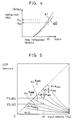
- SUBT1 and SUBT2 are provided with 7 characteristic curves as given in Fig. 5, and the necessary function value can be obtained by linear interpolation of these characteristic curves.
- UCR adjustment value UCRC corresponds to the coefficient k in the equation (1) above. The same applies to M and Y.
- a K is added by an adder 34 in order to control K plate value according to input hue.
- this A K can be supplied from a color correction circuit (not shown), but description is not given here in detail because it is not an essential part of the present invention.
- C, M and Y after UCR processing and K are inputted to TDPC35, TDPM36, TDPY37 and TDPK38 comprising LUT respectively, and density values are converted to value of dot percentage to be outputted to film.
- Density values of C, M, Y and K inputted to TDPC35, TDPM36, TDPY37 and TDPK38 are 10 bits, while the output is 12 bits to obtain high resolution.
- the output signal is inputted to a circuit (not shown in Fig. 3) to convert from dot percentage to QL, and output of this circuit is sent to the output unit 7.
- halftone film in 4 colors of C, M, Y and K can be obtained as a basis for print plate.
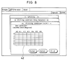
- a utility menu is selected from screen displayed on CRT 6. Further, when a menu for printing condition is selected on utility screen, a screen shown in Fig. 6A is displayed. Then, a user sets desired gray balance by dot percentage for 10 points including a highlight (HL) point, a shadow (SH) point and 8 arbitrary intermediate points for 4 colors of Y, M, C and K respectively, and the user also inputs type of dot, number of lines and whether film output is carried out in positive or negative.
- Fig. 6B shows an example of the setting of these parameters. In Fig. 6B, SQUARE is selected as the type of screen. The number of lines is set to 65 (LPI), and film output is set to negative.
- GBALY0 designates a dot percentage value of Y at HL point
- GBALY9 is a dot percentage value of Y at SH point
- GBALY 1 to 8 are dot percentage values of Y at the intermediate 8 points respectively. The same applies to M, C and K.
- Fig. 9 shows examples of the test patterns for 3/4 conversion.
- Figs. 9A, B, C and D designate respectively a test pattern for Y plate, a test pattern for M plate, a test pattern for C plate, and a test pattern for K plate.
- test patterns for Y plate, M plate and C plate are patterns of lateral stripes having 8-step dot percentage respectively, and the test pattern for K plate is a longitudinal stripe pattern having 7-step dot percentage.
- dot percentage value of each step for each color and dot percentage value of 10 points for each color is as follows:
- dot percentage values of 0, 27, 54, 74, 87, 95 and 100 are given from SK0 to SK6 regardless of the input dot percentage.
- the above numerical values were obtained experimentally at printing as dot percentage values to give the density approximately equally divided.
- dot percentage values at shadow point is obtained by GBALC9, i.e. by the following equation:
- coefficients 32 and 448 are constants to be applied when the dot percentage value is expressed by 12 bits. The same applies to the constants hereinafter.
- Each of the function equations can be obtained from the combination of (x i , y i ) by the method such as quasi-Hermitian interpolation.
- 10 points are inputted from HL to SH for Y, M and C with respect to gray balance, while it is done by 8 steps in the test pattern for 3/4 conversion.
- the reason is as follows: It is also possible to have the test pattern for 3/4 conversion in 10 steps. In this case, there is no need to perform complicated conversion as described above, and the test pattern can be prepared by using dot percentage values as inputted. But, the number of density measuring points are increased and the procedure is more complicated as described below. In contrast, it is possible to input by 8 points from HL to SH for gray balance. In this case, the test pattern can be prepared by using dot percentage values as inputted, but it is desirable that there are more points for gray balance. This is why 10 points are inputted from HL to SH for gray balance, and the dot percentage value inputted are converted to 8 steps.
- the control unit 9 converts the dot percentage inputted in Fig. 6B to 8 steps by the above procedure and gives it to the test pattern generator 12. As the result, the test patterns for 3/4 conversion given in Figs. 9A, B, C and D are outputted from the output unit 7.
- control unit 9 When "end” menu is selected after the density values for all addresses have been inputted, the control unit 9 incorporates the input density values and registers them. Also, processing to obtain LUT to be set to BSCALE1, SUBT1, SUBT2, TDPC35, TDPM36, TDPY37, and TDPK38 is started.
- the control unit 9 incorporates the density of column K0 of the input measured density matrix and plots the dot percentage value of Y with respect to the density value DSK in graph. Then, the plotted points are interpolated by quasi-Hermitian interpolation.
- Fig. 11A shows examples. In this figure, density at a point P is DSK (0, 4) , and dot percentage in this case is LY4 from Fig. 9A.
- the control unit 9 performs the same procedure for C and M and writes the obtained tables in TDPC35 and TDPM36.
- the control unit 9 incorporates the density in the row 0 in Fig. 10 and plots the value of dot percentage of K with respect to the density value DSK. Then, the plotted points are interpolated by quasi-Hermitian interpolation to prepare a graph.
- An example is given in Fig. 11B.
- the density of a point given by Q is DSK (3, 0), and the dot percentage in this case is SK3 as obtained from Fig. 9D.
- all of the dot percentage for Y, M and C are zero.
- the control unit 9 prepares the graph of Fig. 11B and incorporates said table in TDPK38.
- control unit 9 prepares a table to obtain K plate substitution value to be set in BSCALE1 by the following processing:
- the control unit 9 plots the relationship between the measured density value and density value of K for each row of the matrix in Fig. 10.
- 8 graphs given by 50 to 57 in Fig. 12 are obtained.
- the dot percentage value of K of 10 points is converted to the dot percentage value LK i of 8 steps by the following equation: In this case, if 0% continues to be in lower level of GBALK i , only the sample points higher than the highest 0% value are used. In the example of Fig. 6B, the points of HL and 1 are not used.
- TDPK38 a density value DK i to give a dot percentage value LK i is obtained.
- BSCALE2 in case K plate to be reproduced on film defines UCR amount, the same table as BSCALE1 is set. In case K plate to be reproduced and UCR amount must be independent, any function may be set to BSCALE2.
- the control unit 9 prepares a table to set to SUBT1 and SUBT2.
- the control unit 9 prepares a curve by connecting points, which plot the relationship between the measured density value, i.e. density value when 4 colors are overlapped, and the dot percentage of K.
- 4-color overlapping density DRK ij corresponding to a vlaue, which is obtained by accurately dividing the dot percentage of K from 0 to the maximum K MAX in 6 equal parts.
- Fig. 13A the numeral 60 designates a graph of the plotted points in a certain row of Fig.
- the marking "o" indicates points with respect to the dot percentage set by the test pattern for K plate in Fig. 9D.
- the density of K must be arranged with equal spacing.
- the dot percentage set by the test pattern for K plate are set by the spacing of approximately 1/6 to the density value of K100%, but it is not exactly 1/6. Accordingly, by this processing, 4-color overlapping density is obtained when the density of K is 0, K MAX /6, 2K MAX /6, 3K MAX /6, 4K MAX /6, 5K MAX /6 and K MAX .
- the matrix of Fig. 10 is converted to a matrix, which gives 4-color overlapping density when density of K is divided into 6 equal parts.
- the control unit 9 subtracts the value on the ordinate from the value on the abscissa for the points on each graph in Fig. 13B, and the values are plotted in relation to the abscissa. As the result, a graph of Fig. 13C is obtained. As it is evident from the equation (1), this is a graph showing g (d4, d K ), i.e. UCR amount. Therefore, the control unit 9 sets the graphs of Fig. 13C to SUBT1 and SUBT2 as tables.
- the size of the matrix prepared by the test pattern for 3/4 conversion is set to 8 x 7 in the above embodiment, but the other size may be used.
- the dot percentage values of Y, M, C and K to be used in the test pattern for 3/4 conversion the dot percentage value inputted in the screen of Fig. 6B can be used in relation to the matrix size. If interpolation is needed, the interpolation other than quasi-Hermitian interpolation may be applied.
Landscapes
- Engineering & Computer Science (AREA)
- Multimedia (AREA)
- Signal Processing (AREA)
- Color Image Communication Systems (AREA)
- Facsimile Image Signal Circuits (AREA)
- Image Processing (AREA)
Applications Claiming Priority (2)
| Application Number | Priority Date | Filing Date | Title |
|---|---|---|---|
| JP3009554A JP2756040B2 (ja) | 1991-01-30 | 1991-01-30 | Ucr量決定方法及び画像処理装置 |
| JP9554/91 | 1991-01-30 |
Publications (3)
| Publication Number | Publication Date |
|---|---|
| EP0497325A2 true EP0497325A2 (fr) | 1992-08-05 |
| EP0497325A3 EP0497325A3 (en) | 1993-01-20 |
| EP0497325B1 EP0497325B1 (fr) | 1996-12-11 |
Family
ID=11723501
Family Applications (1)
| Application Number | Title | Priority Date | Filing Date |
|---|---|---|---|
| EP92101487A Expired - Lifetime EP0497325B1 (fr) | 1991-01-30 | 1992-01-29 | Procédé pour la détermination de quantité d'UCR et appareil de traitement d'images |
Country Status (4)
| Country | Link |
|---|---|
| US (1) | US5181068A (fr) |
| EP (1) | EP0497325B1 (fr) |
| JP (1) | JP2756040B2 (fr) |
| DE (1) | DE69215704T2 (fr) |
Cited By (8)
| Publication number | Priority date | Publication date | Assignee | Title |
|---|---|---|---|---|
| EP0538901A3 (en) * | 1991-10-25 | 1993-09-15 | Eastman Kodak Company | An adaptive technique for providing accurate tone reproduction control in an imaging system |
| EP0631431A1 (fr) * | 1993-06-21 | 1994-12-28 | Quantel Limited | Appareil de traitement d'image et procédé pour préparer les données représentant une image en couleur |
| EP0665681A3 (fr) * | 1994-01-31 | 1996-05-15 | Canon Kk | Procédé et appareil de traitement d'images. |
| EP0675636A3 (fr) * | 1994-03-29 | 1996-05-29 | Du Pont | Impression en couleur à densité accrue. |
| US5568596A (en) * | 1993-02-25 | 1996-10-22 | Quantel Limited | Image processing system with improved color compensation when transferring between color formats |
| US5832133A (en) * | 1993-04-14 | 1998-11-03 | Quantel, Ltd. | Apparatus and method for altering and displaying attributes of the image |
| EP1531616A3 (fr) * | 2003-11-13 | 2007-12-19 | Samsung Electronics Co., Ltd. | Système d'impression |
| EP2231414A2 (fr) * | 2007-12-20 | 2010-09-29 | The Procter & Gamble Company | Article imprimé et son procédé de fabrication |
Families Citing this family (15)
| Publication number | Priority date | Publication date | Assignee | Title |
|---|---|---|---|---|
| JP3256982B2 (ja) * | 1991-05-14 | 2002-02-18 | 富士ゼロックス株式会社 | 画像処理装置 |
| DE59108877D1 (de) * | 1991-08-20 | 1997-11-20 | Gretag Ag | Verfahren und Vorrichtung zur Ermittlung von Rasterprozentwerten |
| JP2819365B2 (ja) * | 1992-05-28 | 1998-10-30 | キヤノン株式会社 | 画像形成装置 |
| US5612795A (en) * | 1992-11-12 | 1997-03-18 | Linotype-Hell Ag | HSL corrections in CMY color space |
| JP4018755B2 (ja) * | 1995-08-22 | 2007-12-05 | 富士フイルム株式会社 | 色信号変換用トーンカーブ作成方法及び装置 |
| US20010048147A1 (en) * | 1995-09-14 | 2001-12-06 | Hideki Mizuhara | Semiconductor devices passivation film |
| US6031630A (en) * | 1998-05-05 | 2000-02-29 | Hewlett-Packard Company | Method and apparatus for undercolor removal during page pipeline processing |
| JP4282877B2 (ja) * | 2000-06-19 | 2009-06-24 | 富士通株式会社 | カラー画像処理方法 |
| US6628426B2 (en) | 2001-05-22 | 2003-09-30 | Lexmark International, Inc. | Method of halftone screen linearization via continuous gradient patches |
| US7006250B2 (en) * | 2001-09-27 | 2006-02-28 | Lexmark International, Inc. | Method of setting laser power and developer bias in an electrophotographic machine based on an estimated intermediate belt reflectivity |
| US7355753B2 (en) * | 2003-07-14 | 2008-04-08 | Xerox Corporation | Color saturation adjustment |
| JP2007043306A (ja) * | 2005-08-01 | 2007-02-15 | Canon Inc | 画像処理装置および画像処理方法 |
| US7830548B2 (en) * | 2006-01-09 | 2010-11-09 | Adobe Systems Incorporated | Method and apparatus for generating color toning curves |
| JP2007006530A (ja) * | 2006-09-08 | 2007-01-11 | Toppan Printing Co Ltd | 墨版量および分解4原色量の決定方法と、それらを利用した原色変換方法と装置 |
| US7847975B2 (en) * | 2007-07-02 | 2010-12-07 | Xerox Corporation | Converting black to composite black in digital printing |
Family Cites Families (6)
| Publication number | Priority date | Publication date | Assignee | Title |
|---|---|---|---|---|
| JPH0669210B2 (ja) * | 1983-03-08 | 1994-08-31 | キヤノン株式会社 | 画像再生装置 |
| JPS63173646A (ja) * | 1987-01-13 | 1988-07-18 | Ricoh Co Ltd | 画像形成装置 |
| JPH01228376A (ja) * | 1988-03-09 | 1989-09-12 | Minolta Camera Co Ltd | 階調表現方法 |
| JPH0276760A (ja) * | 1988-09-13 | 1990-03-16 | Fuji Xerox Co Ltd | デジタルカラー画像形成装置のトーン修正方法および装置 |
| JPH02178656A (ja) * | 1988-12-28 | 1990-07-11 | Fuji Photo Film Co Ltd | 下色除去方法及びその装置 |
| DE69023825T2 (de) * | 1989-07-17 | 1996-07-25 | Matsushita Electric Ind Co Ltd | Gerät zur Farbbilderzeugung. |
-
1991
- 1991-01-30 JP JP3009554A patent/JP2756040B2/ja not_active Expired - Lifetime
-
1992
- 1992-01-24 US US07/825,492 patent/US5181068A/en not_active Expired - Lifetime
- 1992-01-29 EP EP92101487A patent/EP0497325B1/fr not_active Expired - Lifetime
- 1992-01-29 DE DE69215704T patent/DE69215704T2/de not_active Expired - Fee Related
Cited By (9)
| Publication number | Priority date | Publication date | Assignee | Title |
|---|---|---|---|---|
| EP0538901A3 (en) * | 1991-10-25 | 1993-09-15 | Eastman Kodak Company | An adaptive technique for providing accurate tone reproduction control in an imaging system |
| US5568596A (en) * | 1993-02-25 | 1996-10-22 | Quantel Limited | Image processing system with improved color compensation when transferring between color formats |
| US5832133A (en) * | 1993-04-14 | 1998-11-03 | Quantel, Ltd. | Apparatus and method for altering and displaying attributes of the image |
| EP0631431A1 (fr) * | 1993-06-21 | 1994-12-28 | Quantel Limited | Appareil de traitement d'image et procédé pour préparer les données représentant une image en couleur |
| EP0665681A3 (fr) * | 1994-01-31 | 1996-05-15 | Canon Kk | Procédé et appareil de traitement d'images. |
| US6118558A (en) * | 1994-01-31 | 2000-09-12 | Canon Kabushiki Kaisha | Color image forming method and apparatus |
| EP0675636A3 (fr) * | 1994-03-29 | 1996-05-29 | Du Pont | Impression en couleur à densité accrue. |
| EP1531616A3 (fr) * | 2003-11-13 | 2007-12-19 | Samsung Electronics Co., Ltd. | Système d'impression |
| EP2231414A2 (fr) * | 2007-12-20 | 2010-09-29 | The Procter & Gamble Company | Article imprimé et son procédé de fabrication |
Also Published As
| Publication number | Publication date |
|---|---|
| JP2756040B2 (ja) | 1998-05-25 |
| DE69215704T2 (de) | 1997-04-03 |
| DE69215704D1 (de) | 1997-01-23 |
| US5181068A (en) | 1993-01-19 |
| EP0497325B1 (fr) | 1996-12-11 |
| JPH04253472A (ja) | 1992-09-09 |
| EP0497325A3 (en) | 1993-01-20 |
Similar Documents
| Publication | Publication Date | Title |
|---|---|---|
| EP0497325A2 (fr) | Procédé pour la détermination de quantité d'UCR et appareil de traitement d'images | |
| EP0653879B1 (fr) | Procédé et système de prédiction d'une image de reproduction en couleurs | |
| US5572632A (en) | Universal frame buffer for a rendering device | |
| US6362808B1 (en) | Arrangement for mapping colors between imaging systems and method therefor | |
| US4992862A (en) | Color conversion display apparatus and method | |
| US5764795A (en) | Color image processing apparatus for color matching and color matching processing method | |
| US20080150960A1 (en) | Method for mapping colors between imaging sytems and method therefor | |
| JPH08294014A (ja) | 画像処理装置 | |
| US6151135A (en) | Method and apparatus for color reproduction | |
| US7986448B2 (en) | Image processing apparatus and image processing method for the same | |
| US7271933B2 (en) | Method for creating conversion table for color copier | |
| US20040136014A1 (en) | Smooth gray component replacement strategy that utilizes the full device gamut | |
| US7580150B2 (en) | System and method for reproducing colors on a printing device | |
| JPH04335771A (ja) | 色修正装置 | |
| JP2001045313A (ja) | 色変換方法、色変換装置、色変換プログラム記憶媒体、色補正方法 | |
| JP3908007B2 (ja) | 色変換定義作成方法、色変換定義作成装置、および色変換定義作成プログラム | |
| JP3517569B2 (ja) | 色変換方法 | |
| JPH04304775A (ja) | カラー画像信号の色修正方法 | |
| JP3596584B2 (ja) | 色変換方法 | |
| JP4518408B2 (ja) | 画像処理装置、方法、プログラム | |
| JP3903541B2 (ja) | 色再現方法 | |
| JP2001008045A (ja) | 色信号処理装置 | |
| JP2001086360A (ja) | 色変換方法および色変換装置 | |
| JP3218904B2 (ja) | カラー画像処理装置 | |
| JPH10142775A (ja) | 色再現データ変換方法 |
Legal Events
| Date | Code | Title | Description |
|---|---|---|---|
| PUAI | Public reference made under article 153(3) epc to a published international application that has entered the european phase |
Free format text: ORIGINAL CODE: 0009012 |
|
| AK | Designated contracting states |
Kind code of ref document: A2 Designated state(s): DE FR GB |
|
| PUAL | Search report despatched |
Free format text: ORIGINAL CODE: 0009013 |
|
| AK | Designated contracting states |
Kind code of ref document: A3 Designated state(s): DE FR GB |
|
| 17P | Request for examination filed |
Effective date: 19930716 |
|
| 17Q | First examination report despatched |
Effective date: 19950608 |
|
| GRAG | Despatch of communication of intention to grant |
Free format text: ORIGINAL CODE: EPIDOS AGRA |
|
| GRAH | Despatch of communication of intention to grant a patent |
Free format text: ORIGINAL CODE: EPIDOS IGRA |
|
| GRAH | Despatch of communication of intention to grant a patent |
Free format text: ORIGINAL CODE: EPIDOS IGRA |
|
| GRAA | (expected) grant |
Free format text: ORIGINAL CODE: 0009210 |
|
| AK | Designated contracting states |
Kind code of ref document: B1 Designated state(s): DE FR GB |
|
| REF | Corresponds to: |
Ref document number: 69215704 Country of ref document: DE Date of ref document: 19970123 |
|
| ET | Fr: translation filed | ||
| PLBE | No opposition filed within time limit |
Free format text: ORIGINAL CODE: 0009261 |
|
| STAA | Information on the status of an ep patent application or granted ep patent |
Free format text: STATUS: NO OPPOSITION FILED WITHIN TIME LIMIT |
|
| 26N | No opposition filed | ||
| REG | Reference to a national code |
Ref country code: GB Ref legal event code: IF02 |
|
| REG | Reference to a national code |
Ref country code: GB Ref legal event code: 732E |
|
| REG | Reference to a national code |
Ref country code: FR Ref legal event code: CD Ref country code: FR Ref legal event code: TP |
|
| PGFP | Annual fee paid to national office [announced via postgrant information from national office to epo] |
Ref country code: DE Payment date: 20090123 Year of fee payment: 18 |
|
| PGFP | Annual fee paid to national office [announced via postgrant information from national office to epo] |
Ref country code: GB Payment date: 20090128 Year of fee payment: 18 |
|
| PGFP | Annual fee paid to national office [announced via postgrant information from national office to epo] |
Ref country code: FR Payment date: 20090113 Year of fee payment: 18 |
|
| GBPC | Gb: european patent ceased through non-payment of renewal fee |
Effective date: 20100129 |
|
| REG | Reference to a national code |
Ref country code: FR Ref legal event code: ST Effective date: 20100930 |
|
| PG25 | Lapsed in a contracting state [announced via postgrant information from national office to epo] |
Ref country code: FR Free format text: LAPSE BECAUSE OF NON-PAYMENT OF DUE FEES Effective date: 20100201 |
|
| PG25 | Lapsed in a contracting state [announced via postgrant information from national office to epo] |
Ref country code: DE Free format text: LAPSE BECAUSE OF NON-PAYMENT OF DUE FEES Effective date: 20100803 |
|
| PG25 | Lapsed in a contracting state [announced via postgrant information from national office to epo] |
Ref country code: GB Free format text: LAPSE BECAUSE OF NON-PAYMENT OF DUE FEES Effective date: 20100129 |